1
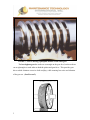
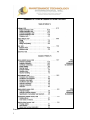
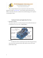
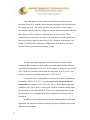
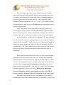
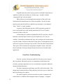
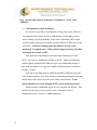
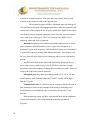
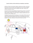
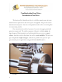
Troubleshooting Gear Drives
Introduction to Gear Drives
The function of the industrial gear drive is to reliably transmit torque and rotary
motion between a prime mover and a driven piece of equipment. The gears are used to
transmit motion and power from one revolving shaft to another or from a revolving shaft
to a reciprocating member.
Gears transmit motion and force by means of successively engaging machined
projections or gear teeth. The smaller component of the pair is called the pinion, the
larger, the gear. When the pinion is on he driving shaft, the gear set acts as a speed
reducer, when the gear drives the pinion, the result is a speed multiplier. The basic gear
type is the spur or straight tooth gear, with teeth cut parallel to the gear axis. Spur
gears transmit power in applications using parallel shafts (SEE FIGURE 1.)
FIGURE 1.
1
When spur gears are used the teeth mesh along their entire length, creating sudden
shifts in load from one tooth to the next, often causing unacceptable noise and vibration.
This problem can be overcome by the helical gear, which has teeth cut at an
angle to the center of rotation, so that the load is transferred progressively along the
length of the tooth from one edge of the gear to the other.
When shafts are not parallel and the drive is transmitted at a 90° angle, the
common gear type used is the bevel gear, with teeth cut on a sloping gear face, rather
than parallel to the shaft.
The spiral bevel gear has teeth cut at an angle to the plane of rotation which, like
the helical gear, transmits power at an angle and reduces noise and vibration.
The hypoid gear resembles a spiral bevel gear, except that the pinion is offset so
that its axis does not intersect the gear axis. These gear sets are used in automobile
differentials. The offset of the axis of hypoid gears introduces additional sliding between
the gear teeth which, when combined with high loads, requires a high quality oil with
extreme pressure additives.
A worm gear consists of a spirally grooved screw moving against a toothed
wheel. In this gear type, where the load is transmitted across sliding, rather than rolling
surfaces, compounded or EP oils are necessary to provide effective lubrication. (SEE
FIGURE 2.)
2
FIGURE 2. A screw driving a phosphor-bronze worm wheel gear.
The herringbone gear has teeth cut at an angle on the gear face, but the teeth are
cut at right angles to each other on both the pinion and gear faces. This provides gear
drives which eliminate excessive shaft end play, while ensuring low noise and vibration
of the gear set. (SEE FIGURE 3.)
3
FIGURE 3.
As gear teeth mesh, they roll and slide over each other. The first contact is
between a point near the root of a driving tooth and a point at the tip of the driven tooth.
As contact progresses, this rolling and sliding action continues as each tooth contacts the
next.
The sliding is always away from the pitch line on the driving teeth and always
toward it on the driven teeth, while rolling is continuous throughout gear meshing. This
combination of sliding and rolling occurs on all meshing gear teeth regardless of type,
although some gear types, such as worm, hypoid and spiral bevel experience additional
radial and sideways sliding.
Given this combination of continuous sliding and rolling contact between gear
teeth, it is easy to understand that fully 50% of gear failures are caused by improper
lubrication, incorrect gear loading or some condition related to lubrication or loading,
such as temperature. (SEE TABLE 1.)
4
TABLE 1.
5
Elastohydrodynamic Lubrication (EHL)
Machine elements such as anti-friction bearings and gear drives operate under
elastohydrodynamic lubrication conditions. EHL is a condition which results when the
surfaces in relative motion are defined as having a low degree of conformity and high
contact pressures. In machine applications such as gears, the surfaces in motion trap the
lubricant film under extreme pressure in the convergent zone as rotation occurs and the
oil’s viscosity can actually increase to the point where the lubricant forms a pseudo-solid
film. This creates a condition where the “almost” solid film separates the two surfaces.
So long as the operating conditions, such as speeds, loads and temperatures are not
exceeded for the particular application, surface contact may never occur due to this
remarkable characteristic of lubricants. The gear teeth contact surfaces may actually
deform elastically, before this pseudo-solid oil film breaks, thus the term
elastohydrodynamic lubrication. (SEE FIGURE 4.)
6
FIGURE 4.
In some gear drive applications, loads or speeds may be such that the EHL oil
film may become ruptured when peaks of the metal surfaces (called asperities) come into
contact. In these severe gear load applications, lubricants with extreme pressure additives
are required.
7
Various chlorine, potassium borate and sulphur-phosphorus compounds are used
primarily as extreme pressure additives, with sulphur-phosphorus being the most
common.
Under these boundary lubrication conditions, most EP additives are activated by a
dramatic temperature increase when asperity contact occurs and react with the metal
surface to form a eutectic, sacrificial film.
The film formed as a result of the EP additive reaction has a lower melting point
than that of the surface of the gear tooth, thus the term “eutectic” and this film protects
the gear tooth surface from further damage or welding of asperities. (SEE FIGURE 5.)
FIGURE 5.
Extreme pressure additives, depending upon their type and application, may have
some limitations. For example, sulphur phosphorus additives may be too chemically
reactive, causing “polishing” wear, particularly in slow speed gear applications (less than
10 ft/min). These same additives may cause corrosive pitting in yellow metals, such as
used in phosphor-bronze worm wheels, particularly at temperatures in excess of 60°C
(140°F).
Often, extremely low ambient temperatures can also affect the efficiency of
sulphur phosphorus EP additives because the reaction rate may be too slow. In these
cases, potassium borate or fatty acid additives may provide protection, however
potassium borate is sensitive to water contamination.
8
These examples illustrate the great care that must be taken when selecting,
applying and caring for gear lubricants. It also illustrates that the lubricant type and
additive compounds used must be considered when troubleshooting gear drive problems
or analyzing gear failures.
Lubricant Selection and Application For Gears
1. Enclosed Gear Drives.
The majority of gear sets are used in enclosed gear boxes and the lubricants used
are subjected to very severe service. (SEE FIGURE 6.)
FIGURE 6.
The lubricant is thrown to and from gear teeth, shafts and support bearings
in the form of mist or spray provided by either splash or pressure fed systems.
(SEE FIGURES 7. & 8.)
9
FIGURE 7. Courtesy of Philadelphia Gear Corporation.
FIGURE 8. Courtesy of Philadelphia Gear Corporation.
10
Lubricants applied in these atomized conditions are subjected to the
oxidizing effects of air with the violent churning and agitation of the lubricant by
the rotating gear sets. This action also raises the temperature, which further
increases the rates of oxidation. Sludge and varnish deposits may result, which in
turn reduces oil flow or interferes with heat removal in oil coolers. These
conditions may in turn reduce viscosity to the point where boundary lubrication
between gear teeth (asperity contact) may occur, raising the temperatures even
further. Eventually these conditions, combined with fluid friction, will cause
lubricant failure, gear and bearing damage, or both.
The final operating temperature of the lubricant is a function of three
conditions; fluid friction, heat generated by any tooth contact and the ambient
temperature surrounding the gear case. As an example, a temperature rise of 90°F
(50°C) of the oil combined with an ambient temperature of 60°F (15.6°C) will
result in a gear drive operating temperature of 150°F (66°C).
As a general rule, oil temperatures of enclosed gear drives should never
exceed 190°–200°F (87.8°–93.3°C) and the best service will be obtained at
temperatures in a range of 120°–140°F (50°–60°C). Where high temperature
conditions occur, oils of lower viscosity with excellent oxidation stability might
be considered, or oil coolers installed. Where severe high temperature or high
load conditions exist, polyalphaolefin (PAO) synthetic lubricants may also be
considered.
In addition to the temperatures encountered and the methods of lubricant
application, the lubricant selected for enclosed gear drives depends upon several
additional considerations.
11
These include gear type, speed, surface finish of gear teeth, reduction
ratio, load characteristics and operating conditions such as contamination levels.
For example, the recommended lubricant used in heavily loaded herringbone or
spiral bevel gears with pitch line velocities of 5–15 m/s (1000–3000 ft/min)
operating in ambient temperatures of 10° to 35°C (50° to 95°F) might be AGMA
5 EP equivalent to an ISO viscosity of 220, unless the gear manufacturer makes a
specific recommendation.
In other applications used in lightly loaded, high speed gearing using
journal support bearings, rust and oxidation inhibited (R & O) lubricants might
provide satisfactory service. Where moderate loads or changes in drive direction
are applied, an R & O oil with anti-wear additives may be successfully applied.
In worm gear drives, compounded oils containing 7–10% fatty acids might
be used successfully, unless the operating temperatures are continually running at
temperatures that exceed 60°C (140°F). In these cases, successful lubrication has
been achieved with synthetic polyalkylene glycol (PAG) lubricants in the ISO
viscosity range of 460. These synthetics have a low friction coefficient with very
high viscosity indices, which result in reduced sliding friction and lower oil
temperatures.
With regard to multiple reduction gear ratios, the first reduction operates
at the highest speed and so requires the lowest oil viscosity, while subsequent
reductions operate at lower speeds thereby requiring lubricant of higher viscosity.
Since the low speed gear in a gear set is usually the most critical in the formation
of an EHL film, a viscosity selection compromise is necessary and an oil of
higher viscosity would be applied, so long as the use of such a lubricant does not
cause the temperature to increase excessively. Whenever the temperature
increases during these arbitrary selection processes, select an oil with the
next lower viscosity, but monitor the oil for any increase in the rates of wear.
Beyond these general gear lubricant recommendations, more detailed
lubricant specifications and recommendations may be obtained by referring to the
12
American Gear Manufacturer’s Association (AGMA) standard 9005-D94. This
AGMA standard provides recommendations for gear oil viscosity selections based
on the pitch line velocity of the final reduction gear for helical, herringbone,
straight bevel, spiral bevel and spur gear drives.
The pitch line velocity can be calculated using the following equations:
Vt = (π np d)/60,000
Where Vt = Pitch line velocity in m/s
np = Pinion speed in rpm
d = Pinion pitch diameter in mm
OR
Vt = (π np d)/12
Where Vt = Pitch line velocity in ft/min
np = Pinion speed in rpm
d = Pinion pitch diameter in inches
An example of how this standard is used is outlined below: The chart
illustrates both ISO and AGMA ratings and how they correspond.
Ambient Temperature
Pitch line velocity of
-40–10°C (1)
-10 + 10°C
+10 to +35°C
+35 to +55°C
15–25 m/s
ISO 68
ISO 68
ISO 150
ISO 320
(3000–5000 ft/min)
(AGMA 2S
(AGMA 2
(AGMA 4 EP
(AGMA 6 EP
Synthetic)
Mineral Oil)
Mineral Oil)
Mineral Oil)
final reduction
(1) All AGMA recommendations that include the letter “S” indicates a synthetic lubricant.
In addition to standard 9005–D94, gear drive operators should also be
familiar with the AGMA viscosity classifications and how these relate to ISO
Viscosity Standards as follows:
AGMA System
13
ISO System
AGMA 0
ISO 32
AGMA 1
ISO 46
AGMA 2
ISO 68
AGMA 3
ISO 100
AGMA 4
ISO 150
AGMA 5
ISO 220
AGMA 6
ISO 320
AGMA 7
ISO 460
AGMA 8
ISO 680
It is also important to note that when AGMA lubricant recommendations
are applied, it would refer to an ISO 150, extreme pressure (EP) gear oil as an
“AGMA 4EP.” If it was referring to an ISO 150 non EP gear oil, the reference to
EP would be dropped (i.e.: AGMA 4).
To summarize, the lubricant characteristics for enclosed gears are as
follows:
a) Correct viscosity at operating temperature.
b) Adequate low temperature fluidity to ensure proper circulation at the
lowest anticipated startup temperature.
c) Excellent oxidation stability, rapid ability for water separation, with good
anti-rust properties.
d) The correct anti-wear or extreme pressure additive levels depending upon
gear system application.
e) Compatibility with sealing materials used on input and output shafts to
eliminate (or reduce) oil leakage.
2. Open Gear Drives
14
Originally lubricants used for open gear drives included such products as
asphaltics (residual oils) and these are of three types; “straight” residuals,
“compounded” and “solvent cutback.”
While still in use in certain applications and parts of the world, most
modern lubricant manufacturers now offer non-asphaltic, solvent free multipurpose greases and oils which are applied to open gearing by “gear dipping,”
“drip,” “brush” or “spray” methods.
As greases, these lubricants may have NLGI consistency grades of 0
(zero) or 00 (double zero) with worked penetrations of 370 to 415 and oil
viscosities of 680 to 1000 cSt.
As lubricating oils, synthetic polyalphaolefin (PAO) extra heavy duty EP
lubricants, with ultra high viscosities of up to 46,000 cSt @ 40°C are now
available. It should be noted that many large, slow speed gear drives that operate
at speeds of under 100 rpm are lubricated as open gears, even though they may be
enclosed in a protective housing to keep out dirt, water and other foreign material.
These gears will be found on such equipment as draglines, hoists, cranes and
shovels and many of the gear designs already discussed can be found in these
applications.
Gear Drive Troubleshooting
Gear drive systems will operate trouble free for many years so long as
they are properly lubricated, kept free of contamination (both internal and
external), operating temperatures are not exceeded and are operated within their
designed loading limitations.
The most common gear tooth shape or profile is called an involute. This
design ensures that the location of the pitch line for the driven gear is identical to
that of the driving gear or pinion.
The relative angular velocity between the two gears is constant for all
tooth contacts, a condition called conjugate action or conjugacy. Conjugate
15
action ensures the smooth transfer of rotary motion from one shaft to another
through proper gear action.
Whenever abnormal conditions occur, such as shaft misalignment,
excessive backlash, inadequate or incorrect lubrication, or excessive loading, the
gear material along the tooth pitch line may become worn, pitted or fatigued, in
turn changing the tooth profile and affecting conjugacy of the gear drive.
Maintenance personnel and troubleshooters must regularly apply
predictive maintenance technologies, such as oil and vibration analysis, to
monitor gear drive conditions and regular inspections must include the following
routine condition monitoring.
a) Listen for abnormal noise.
Noise inspection must focus on changes in sound. Use an
industrial stethoscope or ultrasonic tester to ensure that noise changes are
accurately determined and recorded.
Excessive noise may be the result of sudden fluctuations in drive
speeds, coupling wear, unbalance or misalignment, worn, damaged or
misaligned gear teeth, worn or failed bearings, lack of lubrication, or loose
foundation bolts.
b) Monitor operating temperature.
Remember that mineral base gear lubricants will begin to oxidize
at temperatures that consistently run at 160°F (71°C).
Sudden increases in operating temperatures may be the result of low
lubricant levels, excessive sludge, varnish or contamination causing
increased oil viscosity, damaged or restricted oil cooler, (if equipped)
excessive dirt or foreign material covering part or all of the gear case,
bearing failure or damaged gear teeth (which should correspond with
higher noise levels), overloading, over-greasing of bearings, or too high
oil levels. Monitor temperature differences at all bearing housings. (If
16
one housing is running hotter than the others, this bearing or a gear on the
related shaft may be the culprit). Leaking seals might be the result of high
temperatures which in turn, will create lower than normal oil levels.
c) Inspect air breathers and oil filters.
A plugged or restricted breather will cause excessive housing
pressures to develop, which in turn may cause seal leakage. Breather caps
usually contain wire gauze filters that are intended to restrict the ingestion
of dirt and dust. These filters are useless and should be replaced with
good quality filters with absolute ratings of at least 5 microns to prevent
airborne particulate from entering the gear housing.
Oil filters should be fitted with pressure gauges so that pressure
differential can be determined and monitored. This will help assure that
oil filters are replaced at the correct intervals. If water or particulate
contamination is excessive, side stream or kidney filter systems can be
installed that will remove unwanted and excessive levels of contamination.
Cut open and inspect both oil and air filters if the gear box is so
equipped. The filter media can be spread on a bench and using a good
quality magnifying glass or microscope, contaminants and wear metals
will be obvious. Further testing can be done by passing a magnet under
the filter media. All ferrous materials will move on the surface of the
filter media as the magnet is moved.
d) Determine if contamination is present in the gear drive.
If contamination is suspected, a sample of oil can be obtained in a
glass jar, which is then allowed to sit overnight. When the jar is turned
over, any contaminant will remain visible on the bottom surface of the jar.
17
Water contamination in the lubricant can also be determined very
quickly by placing a few drops of oil on a hot plate. If the oil drops
crackle or sizzle, there is water present, probably in excess of 1000
ppm (0.10% which is detrimental to gear drives).
In many cases, any water, if excessive, will separate from the oil
sample in a jar stored overnight. If contamination by dirt, water or wear
metals appears to be excessive, laboratory oil analysis should be carried
out immediately.
e) Determine if oxidation of the gear lubricant is developing.
It is often difficult to determine if a gear lubricant is becoming
discolored because gear lubricants are normally very dark in color after
some time in service. However if discoloration is obvious, particularly if
the gear drive has been running at high temperatures, oxidation may be
occurring and laboratory testing is recommended.
The Oil Analysis Program
If the routine inspection of the gear drive or its lubricant, results in
evidence of unusual wear, oil thickening, or contamination, analysis of an oil
sample is absolutely necessary. In fact, all critical gear drives should be included
in a regularly scheduled oil analysis program. Before determining what tests are
desirable, it is first necessary for the gear drive operator to understand that any oil
analysis program will only be effective as a condition monitoring technique if the
following principles are consistently applied.
¾ Oil samples must be taken when the oil has reached its normal operating
temperature and if possible should be taken while the system is in operation.
18
¾ The oil sample must be taken at the same location, using the same method each
and every time.
¾ The oil samples should be taken at or near the same operating interval (i.e.:
every 250 or 500 operating hours, etc.) This will ensure that data trending will be
accurate.
¾ The oil samples should be taken using containers approved by (or supplied by) the
laboratory carrying out the analysis. Dirty coca cola bottles are not acceptable!
Oil analysis technologies vary significantly and each may be specifically
designed to determine one or more of three conditions, the condition of the
lubricant itself, the condition of machine components (gears or bearings) and
contamination levels.
a) Oil analysis to determine lubricant condition.
Although there are many and varied analysis tests available, the tests
necessary to determine gear lubricant condition must include viscosity and
acid number. Generally, an increase of 10% or more in viscosity is an
indication that the lubricant has reached the end of its useful life. The
general rule for acid number result is if the acid number has doubled that of
new oil, the lubricant has reached the end of its useful life. Increases in
viscosity and acid levels are definite indicators of oxidation, which suggest
that sludge and varnish will develop and flow will be reduced.
b) Wear particle analysis for machine condition.
There are two common techniques used for wear particle analysis. The
most common technique is spectroscopic analysis which is used to indicate
the levels of ultra-fine particles in the 5–7 micrometer range. (See Figure 9.)
19
Figure 9.
Usually reported in parts-per-million (ppm), these particles include,
among others, iron, copper, aluminum or chromium, which indicate the
metallurgical makeup of gear or bearing components in a gear drive.
This analysis also indicates the various levels of metallic additives, such as
phosphorus and zinc, which indicate typical extreme pressure and anti-wear
additives which may be present in the lubricant. Another element reported
may be silicon, which is an indicator of ingested dirt.
It is important for operators of gear drives to understand that these
levels of wear metals are the result of wear, not necessarily the cause of
wear. These ultra-fine particles will reach certain levels in every lubricated
machine and unless there is a dramatic increase in one or more of the
elements, or a sudden change in overall wear rates, no action is deemed
necessary. In other words, the spectroscopic analysis results reported in ppm
are not as important as are changes or increases in the reported numbers.
Remember that this regularly scheduled program is designed to establish
wear trends. It is critically important that at least three (3) oil analysis results
at the same or similar intervals be carried out in order to establish the trend of
gear drive wear rates. It is for these reasons that operators be familiar with the
20
metallurgical makeup of the various components in the gear drives for which
they are responsible.
The second technique used for particle analysis is analytical ferrography.
Ferrography is a specialized oil analysis technique that can determine the type
of contaminant or wear particle, indicate it’s probable or possible source and
in the case of severe wear, can illustrate the type of damage, such as abrasive,
rolling fatigue, cutting, or adhesive wear.
Ferrography can illustrate such conditions as inadequate lubrication,
excessive heat or contamination and provides a permanent pictorial record of
machine component condition such as gears.
The analysis effectively detects particles in the size range of less than one
(1) to about two hundred fifty (250) micrometers. Analysis is done using a
technique called bichromatic microscopic examination which uses both
reflected and transmitted light sources with green, red and polarized filters to
distinguish the size, composition, shape and texture of ferrous, non-ferrous
and non-metallic particles. (SEE FIGURES 10., 11., 12., 13., 14., 15.)
21
FIGURE 10.
This ferrogram shows both blue and purple temper colors illustrating case
hardened and low alloy steel respectively, indicating abnormal gear wear. An
immediate inspection of the gear drive would be in order.
FIGURE 11.
This ferrogram illustrates clear evidence of metal fatigue, scuffing or scoring
of gear teeth.
22
FIGURE 12.
The red/orange particles illustrate water in the oil and poor lubricant
condition.
FIGURE 13.
This ferrogram illustrates the presence of foreign material in the lubricant
consisting of dirt, sand, or dust probably ingested through poor filler cap
filters, past leaking seals or through careless maintenance.
23
FIGURE 14.
This ferrogram shows small spheres approximately 5 microns in diameter
providing evidence of the onset of rolling element bearing failure. Ultrasonic
testing and/or vibration analysis should be immediately carried out at
bearing caps to determine if a bearing (or bearings) are showing possible
failure.
FIGURE 15.
This ferrogram is typical of severe sliding wear on a gear set, possibly caused
by excessive loads or speeds on the gear tooth surfaces. The metal particles
are in the 20–25 micron size range and these particles could not be reported
through spectroscopic analysis techniques because the particles of wear are too
24
large. Spectroscopic analysis technology is incapable of “seeing” these
conditions.
c) Contamination analysis techniques.
The sources of gear drive contamination are many and varied. Moisture
entering gear boxes can be caused by condensation, careless high pressure
water washing, or by high humidity, where water condensate will be drawn
into the gear box past poorly designed, or poorly filtered oil filler caps, or dip
stick tubes. As little as 250 ppm (parts per million) of water, if left
unchecked, or trapped near a rolling element support bearing, can reduce
bearing life by as much as 50%.
If the gear box is operating at its best operating temperature of 140°F
(60°C), any water or condensation will not evaporate. Many gear lubricants
contain sulphur phosphorus EP additives to prevent scuffing and scoring of
gear teeth, but sulphur is an aggressive additive that can promote acids in the
presence of water.
Gear drives operating in these conditions should be subjected to periodic
water content analysis as part of the condition monitoring maintenance program
and the Karl Fischer water test is the most effective and accurate. Water
content should never exceed 500 ppm (0.05%) in an enclosed gear drive.
Another serious contaminant in gear drives is ingested dirt and dust. Dust
and dirt will enter the gear drive just as water will and the levels of
contamination can be excessive. (SEE FIGURE 16.)
25
FIGURE 16.
Gear drive contamination shown in FIGURE 16. is referred to as silt and
can cause serious damage to gear tooth surfaces or bearings particularly if the
particles become work hardened. (Refer to the description of silt in FIGURE 9.)
The best way to monitor contamination of this type is to regularly carry
out a particle count as part of the condition monitoring program. Particle
counts measure the number and sizes of the contaminants and the results are
converted to ISO cleanliness levels. It is generally agreed among gear
manufacturers that the required lubricant cleanliness levels, based on ISO
Standard 4406:99, should not exceed the 18/16/13 range.
If these levels are exceeded, improved filtration and/or periodic flushing
should be considered as a necessary part of the maintenance program.
Detecting Gear Defects with Vibration Analysis
Gears generate a meshing frequency equal to the number of teeth on the
gear, multiplied by the RPM of the shaft on which the gear is mounted. Unlike
bearings, for which a bearing frequency will not appear unless a bearing
26
problem exists, gear mesh frequencies will “always” be present even if the gear
train is in good condition.
Gear drives with parallel shafts upon which are mounted one (1) gear only
will always have only one frequency. Double or multiple gear reduction units
which have more than one gear per shaft may have several different gear mesh
frequencies and it is for this reason that maintenance personnel should be
familiar with the design and construction of the gear drives in service,
particularly shaft speeds and the number of teeth on each gear. It is suggested
that files be kept containing this information on every gear drive in the facility.
This information should include:
a) A sketch of the gear drive noting the number of shafts, corresponding
shaft speeds and the number of teeth on each gear.
b) The bearing types and part numbers for all shaft support bearings.
c) The marked location of all measurement points (axial, radial and vertical)
from which vibration data can be obtained at bearing caps and shafts.
Gear drives are designed to maintain a constant velocity ratio between the
gears. This condition, called conjugacy, requires that the normal to the
common tangent at the contact point between two gears passes through the
pitch point which lies on the center to center line of the two gears. Any
variation in conjugacy may cause high vibrations due to poor machining,
contact wear, improper gear backlash, or any problem that would cause gear
tooth profiles to deviate from their proper geometry.
Gear mesh frequency is often affected by process variables such as
changes in loads and/or speeds and this frequency is modulated by sidebands
indicating a problem. When sidebands reach ½ the amplitude of the gear mesh
frequency, it indicates that the problem may be severe. Tooth wear may excite
27
a natural or resonant frequency of the gear due to the contact shock created
when the tooth contacts a tooth on the opposite gear.
The resonant frequency will have sidebands spaced at shaft speed.
Gear sets that are designed with improper gear ratios (where the gear teeth only
contact some of the teeth on the driven gear), usually have higher levels of gear
wear than gear drives designed with proper ratios where the gear teeth contact
every tooth on the mating gear. The wave form may show high levels of
impacting where gear wear is suspected.
Backlash and gear wear are similar in that both conditions can excite the
gear’s resonant or natural frequency, however gear wear will appear as a
dominant 1 X gear mesh frequency, while backlash will appear as a dominant 2
X gear mesh frequency, possibly with multiple sidebands. As with gear wear,
the wave form will show high levels of impacting when excessive backlash is
present.
Insufficient backlash on the other hand, particularly in high speed gear
drives where relative tooth velocity exceeds 180 ft/sec, can cause resonant
frequencies caused by escaping oil entrapped between the gear teeth. As the oil
escapes, the loud noises generate resonance.
Misaligned gears may show up on the spectrum at 1 X, 2 X or 3 X gear
mesh frequency with sidebands where the 2 X and 3 X peaks will be higher
than the 1 X peak.
Transmission errors are variations in gear conjugacy which will result in
gear transmission errors such as improper tooth spacing, machining errors,
tooth deflection, or misalignment, any of which may in turn cause worn
bearings.
Most transmission errors will show up in spectral data as high amplitudes
of gear mesh frequency, often with sidebands around the gear natural
frequency.
28
Broken teeth will excite the gear natural frequency that will cause a pulse
at each contact and will appear at 1 X shaft speed. If a broken tooth (or teeth)
is suspected, view the wave form. The high amplitude impacting of the broken
tooth will appear at time intervals equal to the shaft turning speed frequency.
(SEE FIGURE 17.)
29
FIGURE 17.
Taking Vibration Measurements On Gear Drives.
30
For single reduction, parallel shaft gear drives, it is advisable to take
low frequency measurements (for looseness) and high frequency measurements
(for gear condition) at the axial and radial positions as close as possible to the
bearings which support the shafts. Radial measurements should be both
vertical and horizontal to the shaft.
For multiple reduction gear drives, use a high resolution spectrum
analyzer to separate sideband data. Define each area of interest by using
narrow bands of the spectral data and take two radial measurements (horizontal
and vertical) and one axial measurement at each bearing location.
Loads will affect the amplitude(s) of the gear mesh frequencies, so it is
important to take vibration readings over a long enough period of real time to
see all of the spectral data in order to view the effects of load change and
always take all vibration measurements at the same axial and radial locations.
To ensure that amplitudes of vibration frequencies are accurate, use
transducers which have the linear response range necessary to monitor the full
range of frequencies which may be important. Depending upon design, most
good quality magnetically mounted transducers provide linearity to about 3000
Hz. This can be increased to about 5000 Hz by applying special contact
adhesives or fluid between the transducer and magnet and between the magnet
and the machine surface. (Machine surface vibration monitoring contact areas
should be clean and absolutely free of dirt, grease and paint). The best, most
accurate method of transducer mounting is to use threaded stud transducer
mountings. These will provide linearity to about 12000 Hz.
For those troubleshooters using only hand held probes, these will only
provide linearity of about 2000 Hz and may not be effective for sensing critical
vibrations. Using care and with experience, hand held transducers can be used
for frequencies as high as 2000 Hz, however the probe has a resonance between
800 to 1500 Hz, so the response is not as linear as when you mount with
31
adhesives. The probe should be electrically isolated in order to avoid ground
faults which can introduce errors in vibration spectra.
When taking vibration readings, keep the following points in mind:
a) Once mounted, allow the transducer to settle down. Allow 3–5 seconds.
b) Movement, however slight, of the transducer to analyzer cable, can affect
vibration frequency readings, so avoid excessive cable movement.
c) Ensure that there are no loose connections between the transducer to
analyzer cable.
d) When taking vibration readings and a problem is indicated, carry out an
immediate inspection of the gear drive and coupling, base plate and grouting.
Look for problems such as:
1. Oil leaks (which might be a symptom of misalignment or bearing failure).
2. Deteriorated seals (again, this is an indication of a possible misalignment
problem).
3. Loose or damaged mounting or hold down bolts.
4. Cracked or damaged cement pad or base plate.
5. Missing or loose shims under mounting bolts.
6. Broken or loose components.
7. Inspect the drive coupling for problems such as grease or oil leaks, rubber dust,
excessive backlash or looseness (depending upon coupling design).
8. Determine if the bearing and gear housing temperatures are normal.
(Temperatures higher than 77°C (170°F) might be considered abnormal).
9. Inspect drive belts (if used) for looseness, wear or misalignment.
32
For establishing vibration alarm levels, analysts should review the
ANSI/AGMA 6000–A88 guideline which has established criteria for defining
alarm levels for various gear designs in accordance with their pitch line
velocities.
Common Gear Drive Failures and Their Associated Root Causes
The best troubleshooters will recognize gear failures during inspections
based on the condition of the gears themselves. The following photos are examples of
typical gear problems or failures. (SEE FIGURES 18, 19, 20, 21, 22, 23.)
FIGURE 18. This gear shows evidence of pitting, scoring and scuffing of
the gear teeth at and above the pitch line. Note the contamination near
the root of the tooth indicated by the arrow. This gear was subjected to
severe contact stress by overloading, excessive speed, high contamination
levels or poor or inadequate lubrication (or a combination of these
conditions).
33
FIGURE 19. This spur gear shows evidence of abrasion and adhesion on the
surfaces of the gear teeth on the tooth addendum. This severe wear causes
each gear tooth to lose its profile, changing the gear geometry, causing
backlash, vibration and further wear. (The addendum is the area of a gear
tooth from the pitch line to the gear tooth tip). The wear has become so
severe that the tooth contact occurs below the pitch line as shown by the
arrow. Abrasive and adhesive wear can be prevented (or reduced) by
initially running in new gear sets at ½ load, using the recommended
lubricant and ensuring that the lubricant is kept cool, clean and dry.
34
FIGURE 20. This gear shows evidence of misalignment. Note that tooth
contact only covers approximately ⅔ of the teeth as indicated at the point of
the arrow. The problem was located using spectroscopic oil analysis which
indicated high rates of iron wear. A Ferrographic analysis confirmed higher
than normal wear rates and vibration analysis confirmed the misalignment.
FIGURE 21. This gear drive bearing shows clear evidence of water
contamination. Note the discoloration on the inner race and parts of the
cage, as well as the corrosive pitting on all rolling element surfaces.
35
FIGURE 22. As illustrated by the arrow, this gear assembly was subjected to
high load bending fatigue as evidenced by the tiny lines called “beach marks”
just below the break. Beach marks are evidence of excessive tooth loads and
each beach mark line corresponds to intermittent relief of the load as stress is
decreased and reapplied. When a gear is loaded in this manner and
subjected to repeated high load cycles, the affected teeth will fail. Stress
risers in the roots such as inclusions, or deep machining marks, can initiate
these failures.
36
FIGURE 23. This illustrates a typical shock load tooth failure. The
adjacent tooth is also cracked at the root fillet.
Conclusion
Troubleshooting gear problems is not that difficult, so long as the troubleshooter
is fully aware of gear drive design, application, operating conditions, condition
monitoring techniques and effective preventive maintenance practices applicable to the
equipment.
References
ASM Handbook, Volume 18, Friction, Lubrication and Wear Technology,
October 1992, PP 299–312, 535–545.
37
American Gear Manufacturers Association Standard, 9005–D94, Industrial
Gear Lubrication.
The Practical Handbook of Machinery Lubrication, 3rd Edition, L. Leugner, PP
63–69, 180–217.
American Gear Manufacturers Association Standard, 110–04 Nomenclature of
Gear Tooth Failure Modes.
Falk Corporation Service Manual, 108–010, Failure Analysis of Gears and
Related Components.
Drives & Seals, A Tribology Handbook, Editor, M.J. Neale, SAE International,
PP 17–24.
Component Failures, Maintenance and Repair, A Tribology Handbook, Editor,
M.J. Neale, SAE International, PP 18–25, 51–70.
Failure Atlas For Hertz Contact Machine Elements, T.E. Tallian, ASME Press,
1999.
Machinery Analysis and Monitoring, 2nd Edition, John S. Mitchell, Pennwell, PP
214–232.
Vibration Spectrum Analysis, 2nd Edition, Steve Goldman, Industrial Press, PP
87–90, 227–228, 300–314.
Machinery Failure Analysis and Troubleshooting, 2nd Edition, H.P. Bloch and
F.K. Geitner, 1994, Gulf Publishing, PP 125–156.
38