1
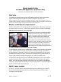
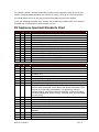
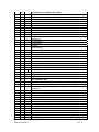
RV
Recreation Vehicle Industry Association
SG
Recreation Vehicle
Study Guide for
Appliance Specialty
Study Guide for the
Certified RV Appliance Specialist Test
Compiled by the Recreation Vehicle Industry Association
Table of Contents
Study Guide for the RV Appliance Certified Specialist Test..................................1
Overview ...........................................................................................................1
What is an RV Service Technician? ..................................................................1
RVST Caeer Ladder..........................................................................................1
What You Must Know to Pass the RV Appliance Certified Specialist Test........2
Resource list......................................................................................................3
Taking the test...................................................................................................3
RV Appliance Specialist Standards Chart .........................................................4
Sign-off Sheet Required Knowledge ...............................................................11
Practice Questions ..........................................................................................11
Answer Key for Practice Questions..........................................................36
RVIA © 11/27/2011
i
Study Guide for the
Certified RV Appliance Specialist Test
Compiled by the Recreation Vehicle Industry Association
Overview
The purpose of this Study Guide is to help the Recreation Vehicle (RV) Service Technician
prepare to take and pass the RVIA/RVDA Certified RV Appliance Specialist Test.
Note: The Certified RV Service Technician and Specialist is a Recreational Vehicle Industry designation. It does not
constitute licensing or permission to perform any function or task controlled by state or local regulations. Technicians are
required to meet all state and local requirements before performing any regulated tasks.
What is an RV Service Technician?
Recreation vehicles have come a long way since the early days of the RV Industry, especially in
the technical sense. So much so, it takes training, dedication and the command of specialized
skills to become a successful RV service technician.
Today’s service technician must acquire and apply
intelligent troubleshooting skills covering the vast
amount of technical equipment found within a wide
range of recreation vehicle types. In addition, a
qualified RV service technician must be proficient
with a variety of hand and powered tools and have
the ability to read, understand, implement and install
numerous accessories and add-on components
common to the RVing lifestyle. Performing proper
and complete preventive maintenance procedures is
yet another must-have skill the qualified service tech will master.
The reward is that, once the above is accomplished, a valued RV service technician will seldom
(if ever), be without a job. To this day, there remains a remarkable shortage of qualified RV
service technicians in the industry to staff not only traditional RV dealerships, but also those of
stand-alone service shops and repair centers that are constantly seeking qualified individuals.
There are many service technicians that open their own mobile RV repair business.
The bottom line is that all good RV service technicians will always have work, even during the
toughest of economic times. It’s been proven; serious RVers will never entirely give up their
lifestyle. They may take shorter, less frequent excursions, but even when fuel costs approach
record highs, they will still be using that RV! And that’s the very reason it is an attractive option to
become a professional RV service technician.
RVST Career Ladder
The Service Technician Career Ladder was developed and launched through the combined
efforts of the RV Dealer Association (RVDA), the RV Industry Association (RVIA) and the
Certification Governing Board.
RVIA © 11/27/2011
1 of 51
Before the Career Ladder was
established there was only one way
to become a Certified RV
Technician and that was to take
and pass a comprehensive
certification test. With the launch of
the Career Ladder there are now
two paths to certification. There is
the traditional path through the
existing RV Service Technician
Certification Test and an alternate
path through achieving Specialty
Certifications.
The certification process begins
with the Candidate level which
provides a basic orientation to the
RV Service Technician career. Next
comes the Registered Technician
level where the core knowledge of
propane, basic electrical, and other
skills are mastered. The technician
can then move on to one of two
paths. He can choose to take the
comprehensive test which covers
all subjects required for certification
or master certification or he can
choose to move through the
individual specialties.
•
•
•
•
•
Appliances
Body
Chassis
Electrical Systems
Plumbing
Once a technician holds all five Specialties, or passes the full certification test at the master level,
and meets the time-in-service requirement he becomes a Master Certified RV Technician.
What You Must Know to Pass the RV Appliance Certified
Specialist Test
The curriculum for the RV Appliance Specialist begins with the DACUM Chart Job and Task
Analysis. This document outlines all the Duties, Tasks and Steps a Specialist is expected to
know. The DACUM is also known as the RV Service Technician Standard and is further broken
down to align with the levels of the RVST Career Path.
RVIA © 11/27/2011
2 of 51
This study guide is focused on the Appliance Specialist level of the Career Path.
The Appliance Specialist Chart lists all of the Duties, Tasks and Steps associated with the
Appliance Specialist level.
Each section begins with the Duties, which will list the main topics covered. The Duties are
followed by the activities a specialist must be able to perform in each area. This list was
developed by working technicians, educators and subject matter experts from across the country
and will provide a valuable check list of what to study for the test.
It should be noted that the number of questions in each area may not equal the number of tasks
listed. Some of the tasks are complex and broad in scope and may be covered by several
questions. Other tasks are simple and narrow in scope and one question may cover several
tasks. The main objective in listing the tasks is to describe accurately what is done on the job, not
to make each task correspond to a particular test question.
The Appliance Specialist Standards Chart begins on page 4.
Sample questions will follow. Although these same questions will not appear on actual tests, they
are in the same format and cover the same topics as the actual test questions.
Resource list
The following resources are available to help you prepare for the Appliance Specialist Test. The
RVIA Textbooks and publications are available through the RVIA Store at www.rvia.org.
RV Propane Systems – RVIA Textbook
RV Electrical Systems – RVIA Textbook
RV Air Conditioners – RVIA Textbook
RV Refrigerators – RVIA Textbook
RV Water Heaters – RVIA Textbook
RV Ranges and Cooktops – RVIA Textbook
RV Heat Appliances – RVIA Textbook
Sign-off Sheets
Taking the test
Get plenty of rest the night before so you will be alert and efficient. Arrive early enough to find the
building and testing room. Be sure to bring your test center admission ticket and current photo
I.D. The proctor will instruct you in filling out the answer booklet if taking the written test or how to
log on to the computer if you are taking the on-line test.
Once testing has begun, keep track of time Do not spend too long on any single question. Be
sure to read each question carefully so you understand exactly what is being asked. Do not mark
answers in the test booklet if taking the written test; they must be marked on the answer sheet.
Your test will not be scored if your answers are not on the answer sheet.
RVIA © 11/27/2011
3 of 51
If a question is difficult, mark the answer that you think is correct and put a check by it in the test
booklet. (Computer-based tests allow you to do this on screen.) Then go on to the next question.
If you finish before time is up, you may go back to the question that you have checked.
It is to your advantage to answer every question. Do not leave any answers blank. Your score will
be based only on the number of correct answers you give.
RV Appliance Specialist Standards Chart
A.
5
c
f
6
a
b
c
d
e
f
g
F.
34
a
b
c
RVIA © 11/27/2011
PROPANE SYSTEMS
Perform propane system tests
Perform appliance tests
--appliance functional tests
--leak test appliance's internal piping/tubing
Complete proper documentation of test results
Troubleshoot propane system faults
Diagnose and Repair erratic propane pressure
Locate and remove debris and oil in line (if possible)
Diagnose and Repair low propane pressure
Diagnose and Repair high propane pressure
Diagnose and Repair restricted flow in propane system
Diagnose and Repair container filling problems
Diagnose and Repair container refrigeration situation
APPLIANCES
Repair/replace/install air conditioning/heat pump units
Verify air flow
--Clean coils and air filter
--Verify ducting system per mfg. specs (size, outlets, duct static pressure,
sq. inches, etc.)
Assess integrity of electrical system
--Verify incoming voltage (static and loaded)
--Verify amp draw
--Verify connections (tight and proper wiring)
--Diagnose/replace electrical components
(selector switch; thermostat; control board; main board; relay board; PTCR
device or kit or start relay; start capacitor; run capacitor(s); motor(s);
overload protector; compressor; heat strip assembly; cold control; change
over thermostat/ambient sensor; relay(s); reversing valve; wire harnesses
and connectors)
Evaluate integrity of refrigerant systems
--Check for leaks
--Inspect/remove and replace coils
--Diagnose/replace compressor
--Accessing, brazing and leak detection
--Evacuate, dehydration, charging and recovering per appropriate
standards
--Inspect/replace reversing valves
--Inspect/replace filter dryer and capillary tubes
--Perform operational refrigerant test
4 of 51
35
a
b
c
d
e
f
g
36
a
b
c
d
e
f
g
h
i
j
37
a
b
c
RVIA © 11/27/2011
Troubleshoot air conditioning problems
Troubleshoot AC and DC voltage
Troubleshoot freeze up
Troubleshoot poor air flow; fan operation
Troubleshoot erratic operation
Troubleshoot no operation
Troubleshoot electronics
Troubleshoot drainage problems out of evaporator
Repair/replace/install water heaters (Pilot)
Visually inspect gas flame, burner tubes, thermocouple tightness, flue vents
Verify gas pressure
Troubleshoot sequence of operation and repair/replace various
components
--thermocouple
--control valve
--burner
--pilot assembly
--temperature and pressure relief valve
--anode rod, if applicable
--orifices (pilot and main burner)
--ECO (energy cut off)
Drain and flush water heater and inspect for calcium deposits
--reestablish air pocket in tank
Verify by-pass is in proper position (if applicable)
Check fittings on tank
Inspect/replace water tank
--reseal flange
Inspect/install/replace reigniter kit
Verify air tight seal at gas line
Perform function test
Repair/replace/install water heaters (DSI-Direct Spark Ignition, 120
VAC, and Motor-Aid)
Visually inspect gas flame, burner tube, flue box, and wires
Verify gas pressure and voltage
Troubleshoot sequence of operation and repair/replace various
components
--thermostat
--ECO
--control valve
--burner
--electrode assembly
--temperature and pressure relief valve
--anode rod, if applicable
--DSI module board
--main burner orifice
--thermal cutoff
--on/off switch
--heating element
--12VDC activated /120 VAC relay
5 of 51
d
e
f
g
h
i
j
k
l
m
n
o
38
a
b
c
d
e
f
g
h
39
a
b
c
d
e
f
g
h
i
j
h
40
a
b
c
RVIA © 11/27/2011
--gas control valve
Drain and flush water heater and inspect fittings for calcium deposits
--reestablish air pocket in tank
Check fittings on tank
Inspect/replace water tank
Test/replace fuse on board when applicable
Verify air tight seal at gas line
Perform function test
Perform probe test on 12V/120 VAC section of DSI board
Test/replace mixing valve
Verify by-pass is in proper position (if applicable)
Motor-aid
Check automotive coolant connections
Check automotive coolant lines
Repair/replace/install water heaters (Electric)
Verify voltage
Visually inspect wires and connections
Verify proper breaker size
Troubleshoot sequence of operation and repair/replace various
components
--thermostat
--ECO
--temperature and pressure relief valve
--anode rod, if applicable
--on/off switch
--heating element
--breaker
--fuses (12V)
Drain and flush water heater and inspect fittings for calcium deposits
--reestablish air pocket in tank
Check fittings on tank
Inspect/replace water tank
Perform function test
Repair/replace/install water heaters (Hydronic)
Clogged orifice issues
Replace orifice
Clean burner chamber
Clean electric eye
Replace ignition valve
Repair/replace pumps
Check and replace heating element
Water flow problems
Winterize
Test/replace mixing valve
Verify/use proper coolant
Troubleshoot water heater problems
Troubleshoot won't light
Troubleshoot tepid water
Troubleshoot won't stay light
6 of 51
d
e
42
a
b
c
d
e
f
43
a
b
c
d
RVIA © 11/27/2011
Troubleshoot TPR (temperature/pressure relief) valve leaks/no air pocket
Troubleshoot won't heat on AC
Install/repair/replace furnaces (Pilot)
Verify gas pressure
Verify voltage and all grounds
Inspect/clean burner, pilot, exhaust tube and air intake
Troubleshoot sequence of operation and repair/replace various
components
--manual shut off valve
--circuit breaker
--on/off switch
--pilot assembly
--thermocouple/thermopile
--gas valve
--thermostat
--burner
--gaskets
--orifices (main burner and pilot)
--fan motor
--fan switch
--relay (time delay, thermostat relay)
--limit switch
--sail switch
--Piezo ignitor and electrode
--blower wheel
--combustion wheel (intake air/blower)
--combustion air hose
--wire and connections
Check integrity of combustion chamber with CO detector
Perform function test
Diagnose/repair/replace furnaces (DSI)
Verify gas pressure
Verify voltage and all grounds
Inspect/clean burner, exhaust tube and air intake
Troubleshoot sequence of operation and repair/replace various
components
--manual shut off valve
--circuit breaker
--on/off switch
--gas valve
--thermostat
--burner
--gaskets
--orifices (main burner)
--fan motor/polarity
--fan switch
--relay (time delay, thermostat relay)
--limit switch
--sail switch
7 of 51
e
f
g
44
a
b
c
d
e
f
g
45
a
b
c
d
e
f
g
46
a
b
c
d
47
a
b
c
d
e
f
RVIA © 11/27/2011
--blower wheel
--combustion wheel (intake air/blower)
--combustion air hose
--electrode assembly
--DSI module board
--wire and connections
Check integrity of combustion chamber with CO detector
Perform function test
Verify DSI board shuts fan motor off (new style)
Inspect and correct ducting and return air
Verify amount of ducting, ducting area and static pressure to mfg. specs
Check for restrictions, damaged ducts, air flow, loose/improper connections
Check adjustable outlets to mfg. specs
Verify return air area to mfg. specs
Verify alignment/seal at plenum
Measure voltage at furnace under load
Verify wire size to mfg. specs
Troubleshoot furnaces problems (Hydronic)
Troubleshoot orifice issues
Replace orifice
Clean burner chamber
Clean electric eye
Replace ignition valve
Replace mixing and zone valves
Repair/replace pumps
Troubleshoot furnace problems (all others)
Troubleshoot voltage problems
Troubleshoot propane pressure problems
Troubleshoot ducting problems
Troubleshoot air flow problem
Install/repair/replace absorption refrigerators (Manual selection)
Verify proper installation and venting per mfg. specs
Verify AC and DC power sources per mfg. specs
Verify propane pressure
Verify leveling of refrigerator per mfg. specs
Diagnose/replace electric components:
--selector switch
--electronic igniter
--Piezo igniter
--electrode
--high voltage cable
--relay
--heating element (AC/DC)
--thermostat
--interior light and switch
--fuses
Diagnose/replace gas components:
--shut off valve
8 of 51
g
h
i
48
a
b
c
d
e
f
g
RVIA © 11/27/2011
--filter, if appropriate
--thermostat
--bypass screw
--safety valve assembly
--thermocouple
--burner assembly
--flue baffle
--flue cap
--orifice
Diagnose/replace cooling unit
Verify seals for air tightness
--inspect and verify proper cabinet combustion seal per mfg. specs and
codes (e.g., NFPA 1192 and CSA Z240)
--door gaskets
--cooling unit
--drip hose
Perform function test
Install/repair/replace absorption refrigerators (Automatic selection)
Verify proper installation and venting per mfg. specs
Verify AC and DC power sources per mfg. specs
Verify propane pressure
Verify leveling of refrigerator per mfg. specs
Diagnose/replace electric components:
--upper circuit board
--lower circuit board
--electronic igniter
--electrode and sensor
--high voltage cable
--relay
--heating element (AC/DC)
--thermostat or thermister
--interior light and switch
--fuses
--climate control heater/high humidity heaters
--valve assembly
--wire harnesses and connectors
--low ambient switch
--power ventilator fan
Diagnose/replace gas components:
--shut off valve
--filter
--thermostat
--solenoid valve assembly (includes safety valve)
--thermocouple or sensor probe
--burner assembly
--flue baffle
--flue cap
--orifice
Diagnose/replace cooling unit
9 of 51
h
i
i
49
a
b
c
d
e
50
a
b
c
d
e
f
g
RVIA © 11/27/2011
Verify seals for air tightness
--inspect and verify proper cabinet combustion seal per mfg. specs and
codes (e.g., NFPA 1192 and CSA Z240)
--door gaskets
--cooling unit
--drip hose
Repair/replace internal ice maker components
--evaporator coil
--compressor
--ice mold assembly
--water valve
--timing motor
--ice mold (micro) switches
--shut off arm
--mold thermostat
--ice ejector
--mold heater
--water lines and connections
--condenser coil
--condenser fan motor
--wire harnesses and connectors
--on/off switch
Perform function test
Troubleshoot refrigerator problems
Check installation and venting
Check power supply
Verify propane pressure
Refrigerator freezes or overcooling
Poor cooling performance
Install/repair/replace ranges and cooktops
Verify gas pressure
Verify grate clips installed
Check lines and fittings for proper clearances from heat sources
Repair/replace components
--oven thermostat
--burners/burner tubes
--oven safety valve
--regulator
--Piezo igniter and electrode
--ignition system (DSI)
--pilot assembly
--gaskets/window/door glass
--burner valves and manifolds
--thermocouple (new models)
Verify range burners not affected by operation of forced air furnace or other
appliances (e.g., microwave)
Perform function test
--verify accuracy of oven thermostat
Verify proper installation (per code and mfg. specifications)
10 of 51
51
a
b
c
d
e
--clearances to adjacent surfaces and flammables
--do not run a hose as supply line inside burner box
Demonstrate general knowledge of appliance repair
Demonstrate knowledge of module board operation
Demonstrate knowledge of gas pressure
Demonstrate knowledge of sequence of operation
Demonstrate knowledge of voltage problems on some appliances
Perform burner adjustments
Sign-off Sheet Required Knowledge
There are seven sign-off sheets associated with the Appliance Specialist. You must know how to
do each test and in what order the steps are performed. The sign-off sheets are included in
Appendix I at the end of this study guide. The entire group of 14 sign-off sheets can be
downloaded from the RV Learning Center’s web site, www.rvlearningcenter.com.
Print the sign-off sheets and perform the tests. Practice the tests until you are sure that you have
thoroughly learned each one.
1.
2.
3.
4.
5.
6.
7.
Air Conditioning
Troubleshooting Air Conditioning
Furnace
Troubleshooting Key Furnace Electrical Components
Water Heater
Refrigerator
Refrigerator Troubleshooting
Practice Questions
PROPANE SYSTEMS
01. When servicing a water heater, propane flow downstream of the solenoid valve is determined
by
A.
B.
C.
D.
performing a System Operating Pressure Test.
installing a monometer at the pressure tap.**
noting the color of the burner flame.
taking a pressure reading at the burner outlet.
02. Which of his five senses will a technician use to find and verify a leaking propane fitting?
A.
B.
C.
D.
Sight.**
Smell.
Touch.
Hearing.
03. Which test instrument can be used to determine that a gas solenoid is functioning?
A. Voltmeter.
B. Ammeter.
RVIA © 11/27/2011
11 of 51
C. Ohmmeter.**
D. Test light.
04. 11 inches water column is the
A.
B.
C.
D.
vapor pressure in a propane bottle at 00F.
maximum pressure indicated by a dial-type manometer.
pressure coming from the second stage of a propane regulator. **
propane regulator lock-up pressure.
05. What percentage of propane flow is required when setting the system operating pressure
(adjusting regulator)?
A.
B.
C.
D.
0%
25%
50%**
75%
06. Which two methods are used to determine if a leak in the propane system exists? 1) Timed
Pressure Drop 2) Leak Detector Solution 3) Regulator Lockup Test 4) Bubble Leak Tester
A.
B.
C.
D.
2 and 4
1 and 3
2 and 3
1 and 4**
07. Which two methods are used to locate a leak in the propane system? 1) Electronic Leak
Detector 2) Leak Detector Solution 3) Pressure-drop Test 4) Hearing (hissing sound).
A.
B.
C.
D.
1 and 2**
2 and 3
3 and 4
1 and 3
08. It is required that you change the fill valve on a mounted ASME tank. To safely remove
propane from the tank you will
A.
B.
C.
D.
open the outage valve and drain the liquid.
remove the fill valve with the cap on.
burn off the propane with a suitable torch.**
open the service valve until the vapor is gone.
09. An opened outage valve is used
A.
B.
C.
D.
to indicate excess pressure.
for container purging.
to determine when container is empty.
to indicate the maximum liquid level.**
10. Backup wrenches are used
RVIA © 11/27/2011
12 of 51
A.
B.
C.
D.
to help break free rusted fasteners.
to prevent damage to propane connections.**
to tighten fasteners during installation.
when primary tools are in use.
11. What propane system fault condition may be present at an appliance in a retracted slideout,
yet not seen when the room is extended?
A.
B.
C.
D.
Pressure drop over time.
Low or no gas pressure.**
Surging gas pressure.
High gas pressure.
12. Automatic changeover regulators are found on
A.
B.
C.
D.
ASME tanks.
20# DOT cylinders.
any propane container.
dual DOT cylinders.**
13. Regarding regulator lockup, which of the following statements is false?
A.
B.
C.
D.
A timed pressure drop test must be preformed after setting the lockup pressure.**
If lockup pressure exceeds 14” w.c. the regulator cannot be repaired.
If system pressure continues to slowly rise after lockup, the regulator cannot be repaired.
A lockup test must be performed after every regulator pressure adjustment.
AIR CONDITIONER
14. The air conditioner is a 120 VAC, 60 Hz appliance. The proper operation range is
A.
B.
C.
D.
between ±5% (114 and 126 VAC).
between ±10% (103.5 and 132 VAC).**
between ±15% (102 and 138 VAC).
between 110 and 130 VAC.
15. To measure the total amperage drawn by an RV air conditioner you would attach an ammeter
to
A.
B.
C.
D.
the black compressor lead.
the A/C circuit breaker in the panelboard.
the A/C junction box.**
both the black and white compressor wires.
16. The evaporator in an RV air conditioner
A.
B.
C.
D.
releases heat into the atmosphere.**
transfers heat from the conditioned space.
transforms refrigerant vapor into a liquid state.
vaporizes condensed moisture removed from the conditioned air.
17. The rotary switch on a manually controlled air conditioner
RVIA © 11/27/2011
13 of 51
A.
B.
C.
D.
determines the direction of air flow.
controls the 120VAC to the compressor.
controls the thermostat.**
selects the heating or cooling functions.
18. Before testing for an open or shorted capacitor, with an ohmmeter you must first
A.
B.
C.
D.
confirm proper voltage at fan terminal.
discharge the capacitor using a ammeter.**
Remove the capacitor from the air conditioner
Short the lead wires from the C and Run terminal.
19. A measurement taken by clamping a test meter around the run (R) or common (C)
compressor lead will indicate
A.
B.
C.
D.
the starting voltage.
nothing because this is an invalid test procedure.
the unloaded compressor draw.
the running amperage.**
20. High side and low side are two types of restrictions found in the sealed refrigerant system.
The basic criteria to use in determining a restriction is (are)
A.
B.
C.
D.
amp draw and pressure.**
low side pressure.
compressor startup amperage and temperature.
temperature differential.
21. Used in evaluating air conditioner performance, the delta-temperature relationship is the
temperature change between the
A.
B.
C.
D.
evaporator and condenser.
high side and low side refrigerants.
air entering and leaving the evaporator coil.**
air entering and leaving the condenser coil.
22. Normal delta temperature is approximately 20 degrees Fahrenheit. An increase in _______
will decrease the delta temperature.
A.
B.
C.
D.
voltage
amperage
humidity**
air temperature
23. The pressure of the refrigerant _______ as the ambient air temperature ______.
A.
B.
C.
D.
increases / decreases
is unaffected / changes
increases / increases **
decreases / increases
RVIA © 11/27/2011
14 of 51
24. The water dripping on the roof of an RV from an A/C unit has been removed from the
A.
B.
C.
D.
moisture inside the RV.**
condenser.
cap tube.
evaporator.
25. Improper or insufficient air flow through the coils of the evaporator and condenser is the
second most common reason why air conditioners stop cooling. What is the main reason?
A.
B.
C.
D.
Compressor failure.
Owner neglect.
Refrigerant leak.
Electrical problem.**
26. Liquid refrigerant is vaporized by the absorption of heat and moisture from inside the coach in
what component?
A.
B.
C.
D.
Condenser.
Evaporator.**
Compressor.
Cap tube.
27. The high temperature overload switch is directly affected by the current draw at the
compressor and also the temperature of the
A.
B.
C.
D.
windings.**
air over the condenser.
return air to the evaporator.
None of the above.
28. To safely discharge a run capacitor, attach the leads of a VOM set to the
A.
B.
C.
D.
lowest AC scale.
lowest DC scale.
highest AC scale.**
highest Ohms scale.
29. A typical heat strip attachment in working condition will measure about hw many Ohms?
A.
B.
C.
D.
7.5
9.5**
11.5 D
13
30. The lowest safe operating line voltage for a roof A/C is
A.
B.
C.
D.
103 VAC. **
107 VAC.
110 VAC.
112 VAC.
RVIA © 11/27/2011
15 of 51
31. When installing a roof A/C, it is approximately 21-feet from the mounting location to the
breaker box. What size Romex is required?
A.
B.
C.
D.
10-gauge.
12-gauge.**
14-gauge.
Any of the above.
32. When mounting a wall thermostat be sure it is installed on an inside wall
A.
B.
C.
D.
as close to the air conditioner as possible.
as far away from the furnace as possible.
near a window.
about five feet above the floor.**
33. 12-VDC is used within a 120-VAC RV air conditioner system
A.
B.
C.
D.
to power a printed circuit board.
to power a relay.
Both A and B.**
12-VDC is never used with a 120-VAC appliance.
34. The first step in troubleshooting an A/C system that does not work at all is to
A.
B.
C.
D.
measure the resistance windings of the compressor.
test the thermostat.
verify the incoming 120-VAC.**
measure the ambient temperatures inside and outside the RV.
35. BTU stands for
A.
B.
C.
D.
Bradford Technical University.
British Technical University.
Bradford Thermal Unit.
British Thermal Unit.**
36. Refrigerant changes from liquid to low pressure vapor at the
A.
B.
C.
D.
evaporator coil.**
condenser coil.
compressor.
capillary tube.
37. Refrigerant changes from a low pressure vapor to a high pressure vapor at the
A.
B.
C.
D.
evaporator coil.
condenser coil.
Compressor.**
capillary tube.
38. Refrigerant changes from a high pressure vapor to a high pressure liquid at the
RVIA © 11/27/2011
16 of 51
A.
B.
C.
D.
evaporator coil.
condenser coil.**
compressor.
capillary tube.
39. In an air conditioner unit, the component in which the heat is absorbed from the living area is
A.
B.
C.
D.
evaporator coil.**
condenser coil.
compressor.
capillary tube.
40. The main difference between the heating and cooling modes of a heat pump is
A.
B.
C.
D.
the type refrigerant must be changed.
the flow of the refrigerant is reversed.**
power source changes from electricity to propane.
There is no difference.
41. What are the four selector switches used in the manufacture of RV air conditioners?
A.
B.
C.
D.
8, 7, 6, and 5 position.
8, 6, 4, and 2 position.
10, 8, 6, and 5 position.**
10, 8, 6, and 4 position.
42. You are checking the compressor. When the outside or inside ambient temperature rises, the
load conditions change and amperage
A.
B.
C.
D.
increases. **
decreases.
remains the same.
is shut off.
43. The 12 VDC operating range for a Dometic air conditioner is
A.
B.
C.
D.
9 to 14.
9 to 16.**
10 to 12.
10 to 14.
44. For Dometic air conditioner normal operation, AC voltage needs to stay within a range of
A.
B.
C.
D.
100.5 – 124.
103.5 - 126.5.**
110 - 130.5.
115 - 126.5.
WATER HEATERS
45. Insufficient millivolt output from the thermocouple may be caused by all of the following
except
RVIA © 11/27/2011
17 of 51
A.
B.
C.
D.
carbon coating.
improper positioning.
low battery voltage.**
dirty contact.
46. When installing a thermocouple do not over tighten, this is a(n) ______ connection.
A.
B.
C.
D.
propane
electrical**
plug-in
thumb-screw
47. A fitting on a water heater control valve is provided for a(an)
A.
B.
C.
D.
propane pressure test port.**
auxiliary propane connection.
burner orifice cleanout.
secondary thermocouple.
48. On a D.S.I water heater the thermostat is located on
A.
B.
C.
D.
in the gas valve water probe.
the inside of the tank.
the outside of the tank.**
the P&T relief valve.
49. The initials E.C.O. on a D.S.I. water heater stand for
A.
B.
C.
D.
Energy Compensated Operation.
Electrical Control Override.
Energy Cutoff Switch.**
Electronically Controlled Operation.
50. A D.S.I. circuit board controls what function?
A.
B.
C.
D.
Sending spark to the electrode while powering the propane valve.**
Powering the propane valve and thermocouple millivolts.
Sensing the flame and thermocouple output.
Water temperature and burner flame size.
51. What material is used in the construction of an Atwood water heater tank?
A.
B.
C.
D.
Steel.
Porcelain on steel.
Aluminum.**
Copper-clad aluminum.
52. To bench test an electric thermostat, attach the leads of your VOM to the contacts of the
thermostat and test for
A. proper voltage.
B. continuity.**
RVIA © 11/27/2011
18 of 51
C. amp draw.
D. A VOM is not used for this test.
53. An accepted method for testing an electric water heater element is to
A. remove element and energize with 120v.
B. check voltage at the element terminals.
C. apply 120v to element terminals while installed and test water temperature after 20
minutes.
D. perform a resistance test.**
54. What is the maximum size heating element that can be used on a 15 amp circuit and still
meet the NEC (electrical code)?
A.
B.
C.
D.
1,200 watts.
1,400 watts.**
1,500 watts.
1,800 watts.
55. An open Energy Cutoff will
A.
B.
C.
D.
allow water to overheat.
cause water to never reach full temperature.
cutoff propane flow, allowing electrical operation only.
shutdown the water heater completely.**
56. A defective electric heating element would indicated by
A.
B.
C.
D.
High voltage at the terminals with low amperage draw.
Voltage at the terminals but no amperage draw.**
Low voltage at the terminals with high amperage draw.
No voltage at the terminals.
57. On a pilot model water heater which component does not affect the flow of propane when
attempting to light the pilot light?
A.
B.
C.
D.
Thermocouple.**
Propane system pressure.
Pilot orifice.
Gas Valve.
58. Which component does not affect the electrode sparking on a DSI water heater?
A.
B.
C.
D.
Thermocouple.
Circuit board.
12 VDC power supply.
Gas valve coil.**
59. Temperature and pressure (T&P) relief valve weeping
A. indicates a defective valve.
RVIA © 11/27/2011
19 of 51
B. is normally controlled by lowering water temperature.
C. is a natural event.**
D. is corrected by opening and closing the valve.
60. Excessive sooting in the combustion chamber of water heater can be caused by
A.
B.
C.
D.
an open propane valve coil.
an overfilled propane container.
high water pressure.
misaligned burner.**
61. A water heater bypass valve that is incorrectly set can cause
A.
B.
C.
D.
variations in water temperature at the faucet.**
a loss of water pressure.
high water temperatures at the faucet.
an interruption of the propane supply to the burner assembly.
62. A component that protects the water heater tank from corrosion is called a(an)
A.
B.
C.
D.
anode.**
cathode.
encapsulator.
tank sealer.
63. Another way to check the heating element is to check resistance. After the power has been
turned off and the wires disconnected from the heating element, you can check the
resistance. The water heater is a 120 VAC, 1000-watt heater. What is the correct resistance?
A.
B.
C.
D.
8.33 ohms.
9 ohms
14.46 ohms.**
16.8 ohms.
64. The pilot model water heater must be supplied with _________ inches nominal water column
of propane in order to work.
A.
B.
C.
D.
7
9
11**
13
65. D.S.I. stands for
A.
B.
C.
D.
Direct Spark Injection.
Double Spark Injection.
Double Spark Ignition.
Direct Spark Ignition.**
66. The thermal cut-off device
RVIA © 11/27/2011
20 of 51
A.
B.
C.
D.
opens the electrical circuit.**
shuts off propane flow.
opens the air shutter.
opens the exhaust vent.
67. The same customer has returned three times with the same problem. Each time you replaced
the circuit board and the D.S.I. water heater works for a short time. What is probably
happening?
A.
B.
C.
D.
Poor quality control during board manufacture.
The consumer is overworking the water heater.
An outside influence is destroying the boards.**
The wrong water heater is installed in the RV.
68. Propane valve coils need a minimum of __________ volts to open.
A.
B.
C.
D.
8
9.5
10.5**
12
69. When checking propane valve coils for resistance, a good coil should have a resistance of
_________ ohms.
A.
B.
C.
D.
1–5
5 – 10
10 – 30
30 – 50*
70. The process of removing sediment from the bottom of a water tank is called
A.
B.
C.
D.
purging.
flushing.**
sanitizing.
recycling.
71. Weeping or dripping of the P&T relief valve while the water heater is operating usually means
A.
B.
C.
D.
the P&T relief valve needs replacement.
the air pocket in the water tank needs to be restored.**
the pipe fittings need new sealant or Teflon Tape.
the P&T relief valve needs flushing.
72. Replace the anode
A.
B.
C.
D.
every six months.
three times per year.
only after the initial warranty period expires.
when it has been reduced in size by 25%.**
73. Atwood's newer adjustable DSI thermostat control allows temperature settings between
RVIA © 11/27/2011
21 of 51
A.
B.
C.
D.
90 - 140 degrees F.
100 - 150 degrees F.
110 - 160 degrees F.
None of the above.**
74. All 120 VAC heating elements for RV water heaters are rated between
A.
B.
C.
D.
500 - 1000 watts.
1000 - 1500 watts.**
1500 - 2000 watts.
None of the above.
75. Electric heating element: 1500-watts. Incoming voltage: 120 VAC. What would be the
resistance measurement of a good, working element?
A.
B.
C.
D.
9.6 ohms.**
10.34 ohms.
12.5 ohms.
16.8 ohms.
76. On a water heater with an adjustable main burner assembly, the preliminary setting of the air
shutter should be
A.
B.
C.
D.
1/4 open position. **
1/4 inch opening.
1/2 inch opening.
half open position.
77. On a DSI water heater the E.C.O. is typically set to
A.
B.
C.
D.
160 degrees F.
170 degrees F.
180 degrees F.**
190 degrees F.
78. When its rating is exceeded, the ECO on a DSI unit will immediately shut down the
A.
B.
C.
D.
PC board.
thermostat..
thermal cut-off.
gas valve.**
79. The resistance measurement of the coil portion of a good DSI gas valve should read between
A.
B.
C.
D.
15 to 30 ohms.
30 to 50 ohms.**
50 to 70 ohms.
70 to 90 ohms.
80. On DSI models with three probes at the igniter, one probe is for the spark, one for the sense
circuit and one for the
RVIA © 11/27/2011
22 of 51
A.
B.
C.
D.
energy cut-off.
ground.**
E.C.O. D.
gas valve.
81. For proper operation, the minimum supply voltage coming into an Atwood DSI model is
A.
B.
C.
D.
9.5 VDC.
10.5 VDC.**
11.5 VDC.
12.5 VDC.
82. To minimize P&T valve weeping, replenish the internal air pocket inside the tank. Which step
below is not a part of that process?
A.
B.
C.
D.
Turn on the water heater. **
Turn off the water pump and/or disconnect the city water.
Open a hot water faucet inside the RV.
Pull or open the handle on the P&T valve and allow water to flow out until it stops.
83. Which of the following is not a function of the PC board?
A.
B.
C.
D.
Powers the coil portion of the gas valve.
Monitors the burner flame.
Produces the micro-amps for the flame sense circuit.**
Performs lockout when necessary.
84. To remedy a lockout condition on a DSI water heater
A.
B.
C.
D.
replace the PC board.
adjust the probe gaps.
turn off the power switch, then turn it back on.**
tighten all the ground connections.
FURNACES
85. The main burner orifice size and combustion air volume of a furnace determines the
A.
B.
C.
D.
furnace type.
efficiency percentage.
BTU rating.**
combustion chamber size.
86. What event causes the blower motor to begin operating?
A.
B.
C.
D.
Burner ignition.
Thermostat calls for heat.**
Sail switch closes.
Combustion wheel draws in exterior air.
87. Residual gases in the combustion chamber are removed before the burner ignites by
RVIA © 11/27/2011
23 of 51
A.
B.
C.
D.
closing the gas valve.
running the blower motor.**
the time delay relay.
diverting room air through the combustion chamber.
88. A millivolt meter is used to test a
A.
B.
C.
D.
blower motor.
TDR.
ECO.
thermocouple.**
89. A ohmmeter issue to test a
A.
B.
C.
D.
thermocouple.
thermostat.**
heat exchanger.
ignition electrode.
90. The component that moves fresh air into the combustion chamber is the
A.
B.
C.
D.
circulating fan.
combustion air wheel.**
heat anticipator.
intake vent.
91. A increase in blower speed and decrease in blower motor amp draw is caused by
A.
B.
C.
D.
air cavitation caused by blocked ducts.**
missing air filter.
incorrect heat anticipator setting.
defective circuit board.
92. Which component is not in the propane delivery system of a D.S.I. furnace?
A.
B.
C.
D.
Orifice.
Manifold.
Pressure tap.
Gas cock.**
93. Primary and secondary air refer to
A.
B.
C.
D.
combustion and circulation.
intake and exhaust.
circulation from normal and high blower speed levels.
air mixed with gas and air use for combustion.**
94. Which component prevents furnace ignition if there is insufficient air to purge the combustion
chamber?
A. Limit switch.
B. Sail switch.**
RVIA © 11/27/2011
24 of 51
C. Time delay relay.
D. Heat anticipator.
95. A high temperature safety device on a furnace is the
A.
B.
C.
D.
Limit switch.**
Sail switch.
Time delay relay.
Heat anticipator.
96. Which will not affect the operation of the sail switch
A.
B.
C.
D.
fan speed.
duct volume.
gas control assembly.**
return air volume.
97. Obstructions in the furnace air vent tubes will create
A.
B.
C.
D.
a lean fuel air mixture.
excessive heat circulation.
blower motor overheating.
a restriction in the flow of secondary air.**
98. When voltage is supplied to the DSI circuit board, there is a(an) ___________ before ignition.
A.
B.
C.
D.
approximate 20 second delay.**
gas pressure check.
lockout sequence.
flame monitoring cycle.
99. The coolant level in a hydronic heating system is checked by
A.
B.
C.
D.
allowing the unit to cool and opening the heat exchanger.
at time of manufacturer, the unit is sealed at the factory.
visual inspection of the expansion tank.**
using the coolant level dipstick.
100. The flame sense function on a DSI furnace equipped with a remote sense circuit senses
the flame via a separate electrode. On a furnace equipped with a local sense circuit, the
flame is actually monitored and sensed via
A.
B.
C.
D.
the ground electrode.
the spark electrode.**
a hard-wired circuit on the circuit board.
the TDR.
101. In any forced air furnace, the resulting products of proper combustion are never mixed with
air inside the RV because
A. owners are directed to close those vents during operation.
RVIA © 11/27/2011
25 of 51
B. the circuit board typically monitors and controls this process automatically.
C. of the design of the sealed combustion chamber coupled with the flow of air through a
heat exchanger.**
D. there are two combustion chambers; one intake and one exhaust.
102. With a proper heat anticipator setting, the furnace should cycle how many times per hour
on average once the system has operated for a few hours?
A.
B.
C.
D.
2 - 3 times.
3 - 4 times.
4 - 5 times.
5 - 6 times.**
103. Another name for a thermopile is ______.
A.
B.
C.
D.
thermocouple.
thermal unit.
Thermostat.
pilot generator.**
104. A sail switch is also called a(n)
A.
B.
C.
D.
fan switch
fan relay
air prover**
limit switch
105. The power source used for the typical modulating gas valve includes
A.
B.
C.
D.
12 VDC.
120 VAC.
Either A or B.
Neither A or B.**
106. The two types of thermostats used in RV heating systems are
A.
B.
C.
D.
bi-metallic and wall.
wall and modulating valve.**
modulating and automatic.
automatic and bi-metallic.
107. The device which controls the furnace operation by reacting to room temperature and
opening and closing a set of contact points which allows current to flow to the control valve
is the
A.
B.
C.
D.
limit switch.
sail switch.
fan switch.
thermostat.**
108. The typical furnace pilot assembly consists of the pilot burner and
RVIA © 11/27/2011
26 of 51
A.
B.
C.
D.
pilot regulator.
pilot orifice.**
pilot filter.
None of the above.
109. When troubleshooting a pilot model furnace, if the gas valve does not open and the
required voltage is present at the valve contacts,
A.
B.
C.
D.
check the delivery line pressure at the furnace.
replace the gas valve.**
check the solenoid(s) of the valve for the proper resistance.
check for proper voltage at the wall thermostat.
110. If the pilot flame will not stay lit when releasing the manual pilot valve,
A.
B.
C.
D.
verify the output of the thermocouple.**
check the solenoid(s) on the gas valve for the proper resistance.
replace the valve.
check the LP pressure at the furnace.
111. To test a thermostat on a gravity heater, simply measure for the correct
A.
B.
C.
D.
continuity.**
voltage.
current.
heat anticipator setting.
112. What type of furnace functions by having the blower engaged prior to the burner lighting?
A.
B.
C.
D.
Catalytic.
Forced air.**
Gravity.
All the above.
113. The purpose for having the blower start before lighting the burner is to
A.
B.
C.
D.
reduce the overall amount of LP used.
minimize carbon build-up on the electrode assembly.
purge the combustion chamber of any residual gases.**
All the above.
114. A furnace "cycling on limit" may have a
A.
B.
C.
D.
restricted return air path.
crushed delivery duct.
faulty limit switch.
All the above.**
115. TDR stands for
A. Temperature Direct Resistance.
B. Thermal Disk Resistor.
RVIA © 11/27/2011
27 of 51
C. Thermostatic Discharge Regulator.
D. Time Delay Relay.**
116. On a pilot model furnace equipped with a piezo ignition system, the gap between the
electrode and burner should be
A.
B.
C.
D.
1/8-inch.
3/16-inch. **
1/4-inch.
3/8-inch.
117. On a forced air furnace, as the thermostat senses the interior air temperature, the contacts
will open removing power from the gas valve. The blower motor will still continue to run until
which device cools enough to stop the current flow to the motor?
A.
B.
C.
D.
Thermocouple.
TDR.**
Limit switch.
Circuit breaker.
118. Since the fan relay circuit is a normally "open" circuit, there should always be voltage from
the furnace circuit breaker to the
A.
B.
C.
D.
limit switch.
sail switch.
fan motor.
fan relay terminal.**
119. On a pilot model forced air furnace, which of the following is NOT a cause for the
symptom… blower runs but fails to ignite burner?
A.
B.
C.
D.
Defective blower relay.**
Low voltage.
Faulty gas valve.
Loose combustion air wheel.
120. A typical sail switch will close its contacts when the blower wheel reaches what percentage
of its rated air flow?
A.
B.
C.
D.
50%.
75%.**
100%.
None of the above.
121. If so equipped, the heat anticipator can be found
A.
B.
C.
D.
at or near the TDR.
attached to the gas valve (pilot models only).
on the circuit board (DSI models only).
in the wall thermostat.**
RVIA © 11/27/2011
28 of 51
122. On a DSI furnace, the circuit board will
A.
B.
C.
D.
allow the blower to purge the combustion chamber for a set period of time.
open the gas valve.
confirm the presence of a burner flame.
All the above.**
123. While the furnace is operating, the TDR will draw approximately
A.
B.
C.
D.
.2-amp. **
.5-amp.
1-amp.
the same amount of current as the heat anticipator.
124. Which component contains a bimetal disk, a coil, and contacts for the thermostat, ground
connection and positive 12-volts DC?
A.
B.
C.
D.
Circuit board.
Electronic wall thermostat.
TDR.**
Resettable limit switch.
125. When troubleshooting the redundant gas valve on the DSI forced air furnace, a good coil
will measure
A.
B.
C.
D.
10 - 20 Ohms each.
20 - 30 Ohms each.
30 - 50 Ohms each.**
above 50 Ohms each.
126. The voltage range for proper heater operation is
A.
B.
C.
D.
10.5 to 13.5 VDC **
12.5 to 16 VDC
110 to 130 VAC D
120 to 140 VAC
127. The thermocouple on a gravity heater creates _____ millivolts.
A.
B.
C.
D.
5 to 15
10 to 20
20 to 30**
20 to 40
128. Forced air gravity heaters should have a voltage of between _____ and ____ at the furnace
during operation.
A.
B.
C.
D.
8.0 and 12.5 VDC
10.5 and 13.5 VDC**
110 and 130 VAC
120 and 140 VAC
RVIA © 11/27/2011
29 of 51
129. The device that controls the fan causing it to purge the combustion chamber of any residual
gases before the furnace attempts to light is called the
A.
B.
C.
D.
limit Switch.
sail Switch.
D.S.I. circuit board.**
Time Delay Relay.
130. The thermostat has an anticipator which will burn out if the TDR and gas value draw more
than _____ amps.
A.
B.
C.
D.
0.2
0.5
0.7
1.0**
131. Some manufacturers recommend replacing the gas solenoid valve on a D.S.I. furnace if the
coil is defective. One way to know if a coil is defective is when the resistance is not within a
range of ________ ohms.
A.
B.
C.
D.
20 to 40
30 to 50**
40 to 60
of over 60
132. The component of a furnace that sends a high voltage spark to the electrode assembly and
sends 12 VDC to the gas solenoid valve is the______.
A.
B.
C.
D.
generator board.
D.S.I. circuit board.**
limit switch.
sail switch.
133. The central hot water heating system has an electrical heating element which is ________
watts.
A.
B.
C.
D.
800
1200
1475
1650**
134. The central hot water heating system has a water and antifreeze ratio of
A.
B.
C.
D.
1 to 1.**
1 to 2.
3 to 4.
2 to 1.
135. To prevent freezing of the water system, adjust the bay thermostat on the central hot water
heating system to ______ degrees.
RVIA © 11/27/2011
30 of 51
A.
B.
C.
D.
20 to 30°F (-7 to -1°C)
30 to 40°F (-1 to 4°C)
40 to 50°F (4 to 10°C)**
50 to 60°F (10 to 16°C)
3
136. Normal operating temperature for the central hot water heating system is _______ degrees.
A.
B.
C.
D.
120 to 140°F (49 to 60°C)
140 to 165°F (60 to 74°C)
165 to 180°F (74 to 82°C)
175 to 200°F (82 to 93°C)**
REFRIGERATORS
137. Only pure ammonia vapor is present after the contents pass through which component?
A.
B.
C.
D.
Boiler.
Pump tube.
Rectifier.**
Absorber.
138. The static pressure of the hydrogen vapor inside the cooling unit
A.
B.
C.
D.
is 150 PSI.
is 250 PSI.**
is 600 PSI.
varies with the heat source.
139. The purpose of sodium chromate inside the cooling unit is to
A.
B.
C.
D.
regulate the condensation of ammonia vapor.
remove water molecules from the weak ammonia mixture.
protect the insides of the piping.**
All the above.
140. Which component is not associated with the electric operation of the RV refrigerator?
A.
B.
C.
D.
Boiler.
Water separator.
Flue.**
None of the above.
141. In which component does ammonia cool into a liquid?
A.
B.
C.
D.
Generator.
Condenser.**
Evaporator.
Absorber.
142. What removes heat from the ammonia vapor?
A. Absorber coils.
RVIA © 11/27/2011
31 of 51
B. Low temperature evaporator.
C. High temperature evaporator.
D. Air moving through the condenser fins**.
143. During a refrigerator installation, never allow the side clearances to extend beyond
A.
B.
C.
D.
1/2-inch.**
1/4-inch.
1/8-inch.
the width of the cabinet braces.
144. Correct energy source priority for a Norcold automatic refrigerator is
A.
B.
C.
D.
120-VAC, 12-VDC, LP.
12-VDC, LP, 120-VAC.
LP, 120-VAC, 12-VDC.
120-VAC, LP, 12-VDC.**
145. Correct energy source priority for a Dometic automatic refrigerator is
A.
B.
C.
D.
120-VAC, 12-VDC, LP.**
12-VDC, LP, 120-VAC.
LP, 120-VAC, 12-VDC.
120-VAC, LP, 12-VDC.
146. The absorption refrigerator cooling unit consists of the following components:
A.
B.
C.
D.
boiler, condenser, motor and absorber.
boiler, condenser, evaporator and absorber.**
boiler, motor, evaporator, and absorber.
motor, condenser, evaporator and absorber.
147. Hydrogen Gas has a maximum pressure of _________ PSI when heated.
A.
B.
C.
D.
400
500
600**
750
148. An excessive amount of heat in the cooling unit will cause
A.
B.
C.
D.
the water to vaporize.
the hydrogen gas to vaporize.
both the hydrogen and ammonia to vaporize.
both the water and ammonia to vaporize.**
149. ______ requires the refrigerator to be installed in such a manner as to provide complete
separation of the combustion system and the interior atmosphere of the RV.
A. NFPA 1192 /CSA Z240**
B. Manufacturer installation instruction
C. NEC 501C / UL 14-5
RVIA © 11/27/2011
32 of 51
D. UL 14-5 / NEC
150. The proper voltage operating range of a 120 VAC, 60 Hz refrigerator is
A.
B.
C.
D.
108-132 VAC.**
108-121 VAC.
102-138 VAC.
102-121 VAC.
151. For the refrigerator to work properly on propane, the propane pressure should be
A.
B.
C.
D.
9 " W.C.
10 " W.C.
11 " W.C.**
12 " W.C.
152. The proper procedure to clean an orifice assembly is to soak it in
A.
B.
C.
D.
gasoline.
hot soapy water.
an alcohol based solvent.**
sodium chromate.
153. If the refrigerator is not running on AC, the first thing to check is the
A.
B.
C.
D.
incoming Voltage.**
on/off switch.
circuit Breaker.
safety solenoid.
154. To bench test an electric thermostat, attach the leads of your VOM to the contacts of the
thermostat and test for
A.
B.
C.
D.
proper voltage.
continuity.**
amp draw.
A VOM is not used for this test.
155. When a capillary tube has lost its charge, it is necessary to
A.
B.
C.
D.
replace the thermostat. **
replace the capillary tube.
recharge the cap tube.
replace the cooling core.
156. Where hydrogen gas is combined with liquid ammonia?
A.
B.
C.
D.
Boiler.
Evaporator.**
Absorber.
Condenser.
RVIA © 11/27/2011
33 of 51
157. In an absorption refrigerator the _______ vaporizes in the hydrogen gas atmosphere and
absorbs heat from inside the refrigerator.
A.
B.
C.
D.
ammonia**
neutralizing agent
water
zorbic acid
RANGES AND COOKTOP
158. Eye-level ranges are no longer produced because of what inherent factor?
A.
B.
C.
D.
They consumed too much LP.
They would fatigue and collapse under their own weight.
They became too costly to the RV manufacturer.**
The ovens were chronically inaccurate.
159. The pilot flame on an RV range is typically controlled by either a manual on/off valve or by
the
A.
B.
C.
D.
oven thermostat.**
safety valve.
consumer.
flash tube positioning.
160. The oven safety valve
A. essentially controls the function of the thermostat.
B. contains a thermal bulb positioned in upper rear section of the oven cavity.
C. allows propane vapor to flow to the main burner when the pilot is on the lower pilot
flame setting.
D. contains a thermal bulb which is heated by the standing oven pilot.**
161. A cooking appliance with top burners only is called a
A.
B.
C.
D.
stove.
cooktop.**
manifold.
range.
162. Care must be taken when replacing burners and orifices to ensure
A.
B.
C.
D.
compatibility with piping size.
compliance with ANSI/NFPA 1192.
matching of Btu/hr ratings.**
you do not exceed the propane supply capacity.
163. A thermal bulb performs which function?
A. Controls gas flow.
B. Senses oven temperature.**
RVIA © 11/27/2011
34 of 51
C. Maintains pilot light.
D. Controls safety valve.
164. Which flame sensing device controls the gas flow to the oven standing pilot?
A.
B.
C.
D.
Pilot assembly.
Thermal bulb.
Safety valve.
There is no flame sensing device.**
165. A well adjusted burner flame can be recognized by a
A.
B.
C.
D.
slight hissing sound.
blue flame without a primary inner cone.
crisp blue flame with blue inner crown.**
soft blue cone with inner yellow crown.
166. Burner orifice rating are identified by
A.
B.
C.
D.
color.**
weight.
measuring size.
stamped ID number.
167. When trouble shooting a poorly functioning cooktop burner first check the
A.
B.
C.
D.
burner alignment.
air shutter.
propane pressure.**
appliance regulator.
RVIA © 11/27/2011
35 of 51
Answer Key for Practice Questions
001. B
002. A
003. C
004. C
005. C
006. D
007. A
008. C
009. D
010. B
011. B
012. D
013. A
014. B
015. C
016. A
017. C
018. B
019. D
020. A
021. C
022. C
023. C
024. A
025. D
026. B
027. A
028. C
029. B
030. A
031. B
032. D
033. C
034. C
035. C
036. A
037. C
038. B
039. A
040. B
041. C
042. A
RVIA © 11/27/2011
043. B
044. B
045. C
046. B
047. A
048. C
049. C
050. A
051. C
052. B
053. D
054. B
055. D
056. B
057. A
058. D
059. C
060. D
061. A
062. A
063. C
064. C
065. D
066. A
067. C
068. C
069. D
070. B
071. B
072. D
073. D
074. B
075. A
076. A
077. C
078. D
079. B
080. B
081. B
082. A
083. C
084. C
085. C
086. B
087. B
088. D
089. B
090. B
091. A
092. D
093. D
094. B
095. A
096. C
097. D
098. A
099. C
100. A
101. C
102. D
103. D
104. C
105. D
106. B
107. D
108. B
109. B
110. A
111. A
112. B
113. C
114. D
115. D
116. B
117. B
118. D
119. A
120. B
121. D
122. D
123. A
124. C
125. C
126. A
127. C
128. B
129. C
130. D
131. B
132. B
133. D
134. A
135. C
136. D
137. C
138. B
139. C
140. C
141. B
142. D
143. A
144. D
145. A
146. B
147. C
148. D
149. A
150. A
151. C
152. C
153. A
154. B
155. A
156. B
157. A
158. C
159. A
160. D
161. B
162. C
163. B
164. D
165. C
166. A
167. C
36 of 51
RVIA © 11/27/2011
37 of 51
Appendix 1 – Signoff Sheets
Air Conditioning
Printed Technician Name
ID Number
Address
Telephone Number
City
State
Zip Code
STEP
Initials
Date
Install Or Verify The Accuracy Of An Air Conditioner’s Installation
The candidate must describe and record these characteristics of
an air conditioner.
Did the candidate
Record the air conditioner model number?
Record the air conditioner serial number?
Record the type of air conditioner (ducted or non-ducted)?
Indicate OEM or Aftermarket installation?
Verify compatibility of the component parts (i.e., Rooftop unit, Ceiling plenum,
Wall control)?
The candidate must confirm the proper installation of an
airconditioner (including the ceiling plenum)
Did the candidate
Verify the air conditioner is bolted down properly (Gasket compression
approximately 50%)?
Verify proper ceiling plenum installation including return and supply air
separation?
Verify installation wiring conforms to all applicable codes, proper wire gauge,
breaker size, etc.?
Verify adequacy of ducting, vents, and size of registers per installation
instructions/service manual?
Accurately diagnose and repair problems, if any exist, in accordance with the
installation instructions?
Evaluate Air Conditioner Performance
Measure line voltage to the air conditioner
Did the candidate
Use a VOM to check incoming static voltage at the air conditioner voltage
connection points?
Start the air conditioner on high cool and check this voltage reading again after
applying the load?
Interpret the accuracy and validity of these voltage readings (should be between
103.5 & 126.5 VAC)?
Correctly diagnose and repair problems, if any exist, in accordance with the
service manual if voltage readings are not within the pre-described limits?
Measure the temperature difference across the evaporator (supply
& return air temperatures)
Did the candidate
Start the air conditioner in the high cool position?
Allow the air conditioner to run for a minimum of 30 minutes?
Open all discharge and supply air registers completely?
Place a thermometer near the return air grille/louvers and measure the air
temperature?
Place a thermometer in the supply register/louver and measure the air
temperature?
RVIA © 11/27/2011
38 of 51
Sign-off sheet revised June 23, 2008
Appendix 1 – Signoff Sheets
Verify accuracy and validity of this calculation to the manufacturer specifications;
20 degrees difference nominal (See service manual)?
Accurately diagnose and repair problems, if any exist, in accordance with the
service manual?
Measure the compressor amperage
Did the candidate
Start the air conditioner in the high cool position?
Allow the air conditioner to run for a minimum of 30 minutes?
Measure the outdoor ambient temperature?
Record the compressor rated load amperage (RLA) printed on the air
conditioners rating plate?
Use the information found in the service manual to calculate correct amperage
based on RLA and outdoor temperature?
Read the compressor amperage with an Ammeter?
Confirm the measure compressor amperage and calculated amperages are
approx. equal?
Accurately diagnose and repair problems, if any exist, in accordance with the
service manual?
Subtract the supply air temperature from the return air temperature?
RVIA © 11/27/2011
39 of 51
Sign-off sheet revised June 23, 2008
Appendix 1 – Signoff Sheets
Troubleshooting Air Conditioner
Key Electrical Components
Sign-Off Sheet
Printed Technician Name
ID Number
Address
Telephone Number
City
State
Zip Code
STEP
Initials
Date
Note: Due to product differences the candidate must consult the
service manual for individual component specifications,
procedures, and sequence of operation
Air Conditioner Compressor
Did the candidate
Correctly measure compressor amperage?
Correctly measure resistance of the compressor motor windings?
Remove all electrical power from the air conditioner; remove all wires from the
compressor; check terminals C&R, C&S, R&S?
Measure running voltage at the proper location on the compressor?
Accurately diagnose compressor problems, if any exist, in accordance with the
service manual?
Air Conditioner Fan Motor
Did the candidate
Correctly measure fan motor amperage?
Correctly measure resistance of the fan motor windings?
Remove all electrical power from the air conditioner; remove all wires from the
fan motor; check motor windings for short, open or ground (see service manual)?
Measure running voltage at the proper location on the fan motor?
Accurately diagnose and repair fan motor problems, if any exist, in accordance
with the service manual?
Air Conditioner Capacitor(s)
Did the candidate
Properly discharge the capacitor(s) per the service manual?
Properly test the capacitor(s) per the service manual?
Accurately diagnose and repair capacitor problems, if any exist, in accordance
with the service manual?
Select either manual thermostat or wall thermostat
Manual Thermostat
Did the candidate
Remove all electrical power from the air conditioner; remove all wires from the
thermostat; check the thermostat with an Ohmmeter?
Accurately diagnose and repair the thermostat problems, if any exist, in
accordance with the service manual?
Manual Selector Switch
Did the candidate
Remove electrical power from the air conditioner; remove wires from the switch;
check the selector switch with an Ohmmeter?
Wall Thermostat
Did the candidate
RVIA © 11/27/2011
40 of 51
Sign-off sheet revised June 23, 2008
Appendix 1 – Signoff Sheets
Measure low voltage power into the wall thermostat?
Measure low voltage power out of the wall thermostat?
Accurately diagnose and repair thermostat problems, if any exist, in accordance
with the service manual?
Upper Control Box Assembly
Did the candidate
Measure low voltage power from the wall thermostat to the control box?
Measure high voltage power (120VAC) out of the upper control box assembly to
the rooftop air conditioner?
Accurately diagnose and repair control box assembly problems, if any exist, in
accordance with the service manual?
Accurately diagnose and repair selector switch problems, if any exist, in
accordance with the service manual?
RVIA © 11/27/2011
41 of 51
Sign-off sheet revised June 23, 2008
Appendix 1 – Signoff Sheets
Furnace
Sign-Off Sheet
Printed Technician Name
ID Number
Address
Telephone Number
City
State
Zip Code
STEP
Initials
Install or Verify the Accuracy of a Furnace’s Installation
The candidate must describe and record these characteristics of a
furnace.
Did the candidate
Record the furnace model number?
Record the furnace serial number?
Record the type of furnace system?
Indicate OEM or Aftermarket installation?
The candidate must confirm the proper installation of a furnace.
Did the candidate
Verify proper ducting?
Verify proper return air?
Verify proper gas pressure at furnace?
Verify proper propane connections and conduct a leak test ?
Document leak test results?
Verify proper DC/AC voltage at furnace?
Verify proper exhaust vent system?
Verify proper seals at door, vents etc.?
Accurately diagnose and repair installation problems, if any exist, in accordance with
the installation manual?
Evaluate Furnace Performance
Measure line voltage at the furnace
Did the candidate
Check incoming voltage at the wire connections on side of furnace? Nominal voltage
should be 10.5-13.5 VDC under unloaded condition.
Turn furnace on?
Verify ignition?
Check voltage at the wire connections on side of furnace? Nominal voltage should be
10.5-13.5 VDC under loaded condition.
Accurately diagnose and repair problems, if any exist, in accordance with the service
manual?
Measure propane pressure at furnace
Did the candidate
Turn propane off at container?
Install manometer at pressure test port?
Turn propane on at container?
Check for proper gas pressure (see service manual)?
RVIA © 11/27/2011
42 of 51
Sign-off sheet revised June 23, 2008
Date
Appendix 1 – Signoff Sheets
Document measurement results?
Accurately diagnose and repair problems, if any exist, in accordance with the service
manual?
Evaluate proper air flow
Did the candidate
Open all discharge registers and any closeable registers(see installation and or service
manual for requirements)?
Verify air discharge by feel or using an air speed indicator?
Verify that the discharge is warm?
Accurately diagnose and repair problems, if any exist, in accordance with the service
manual?
Evaluate return air flow
Did the candidate
Verify proper return air opening size (see installation and or installation manual)?
Accurately diagnose and repair problems, if any exist, in accordance with the service
manual?
RVIA © 11/27/2011
43 of 51
Sign-off sheet revised June 23, 2008
Appendix 1 – Signoff Sheets
Troubleshooting Key Furnace Electrical Components
Sign-Off Sheet
Printed Technician Name
ID Number
Address
Telephone Number
City
State
Zip Code
STEP
Initials
Date
Troubleshoot Key Furnace Electrical Components
Did the candidate verify sequence of operation per the service manual to
evaluate the following components?
Thermostat
Did the candidate
Verify proper height and location per installation and or service manual?
Verify voltage to thermostat and voltage out of thermostat to furnace (see service
manual)?
On/Off Switch
Did the candidate
Remove power wires and check switch for continuity using an ohmmeter?
Accurately diagnose and repair problems, if any exist, in accordance with the
service manual?
Circuit Breaker (If applicable)
Did the candidate
Measure DC voltage in and out of circuit breaker?
Accurately diagnose and repair problems, if any exist, in accordance with the
service manual?
Time Delay Relay (if applicable)
Did the candidate
Confirm DC voltage at proper terminals (refer to service manual)?
Accurately diagnose and repair problems, if any exist, in accordance with the
service manual?
Blower Motor
Did the candidate
Confirm DC voltage to blower motor?
Measure DC amperage at motor (see service manual)?
Accurately diagnose and repair problems, if any exist, in accordance with the
service manual?
Limit Switch
Did the candidate
Verify continuity or DC voltage through limit switch?
Accurately diagnose and repair problems, if any exist, in accordance with the
service manual?
Sail Switch
Did the candidate
Verify continuity or DC voltage through sail switch?
Accurately diagnose and repair problems, if any exist, in accordance with the
service manual?
RVIA © 11/27/2011
44 of 51
Sign-off sheet revised June 23, 2008
Appendix 1 – Signoff Sheets
STEP
Initials
Date
Either Fan Control Circuit Board
Verify proper DC voltage to circuit board (see manual)?
Verify function of circuit board (see manual functions)?
Spark
DC voltage to gas valve
Sense flame
Energize relay to start fan
Accurately diagnose and repair problems, if any exist, in accordance with the
service manual?
Or Ignition Board
Did the candidate
Verify proper DC voltage to ignition board (see manual)?
Verify function of ignition board (see manual functions)?
Spark
DC voltage to gas valve
Sense flame
Accurately diagnose and repair problems, if any exist, in accordance with the
service manual?
Gas Valve
Did the candidate
Measure proper voltage at valve?
Remove power wires and check coils for proper resistance 30-50 ohms?
Check for proper gas flow exiting valve orphic (if ignition fails check by smell or
use manometer)?
Accurately diagnose and repair problems, if any exist, in accordance with the
service manual?
Electrode
Did the candidate
Check for proper gap (see manual)?
Check for proper spark across electrode to ground?
Accurately diagnose and repair problems, if any exist, in accordance with the
service manual?
Did the candidate
RVIA © 11/27/2011
45 of 51
Sign-off sheet revised June 23, 2008
Appendix 1 – Signoff Sheets
Water Heater
Sign-Off Sheet
Printed Technician Name
ID Number
Address
Telephone Number
City
State
Zip Code
STEP
Initials
Date
Install or Verify The Accuracy of a Water Heater’s Installation
The candidate must describe and record these characteristics of a
water heater.
Did the candidate
Record the water heater model number?
Record the water heater serial number?
Verify type of control system?
The candidate must confirm the proper installation of a unit
Did the candidate
Check the seal around the flange?
Confirm the vent is clear and properly gapped from door screen (0 to 1/4" - see
installation manual)?
Confirm the gas line is properly sealed from interior of coach?
Verify wiring complies with NEC code (if applicable)?
Conduct a leak test on the propane connection to the water heater?
Verify the water heater is properly supported?
Accurately diagnose and repair problems, if any exist, in accordance with the
installation instructions?
Evaluate Water Heater Performance
Measure propane pressure at water heater
Did the candidate
Turn propane off at the container?
Install manometer on the provided pressure test port?
Turn propane on at the container?
Check for proper propane pressure (see service manual)?
Document results?
Accurately diagnose and repair problems, if any exist, in accordance with the
service manual?
Verify customer complaint
Did the candidate
Visually inspect gas flame, burner tube, flu box, and wires?
Troubleshoot Key Components
Determine the proper pilot control type ( pilot, DSI or electric)
Pilot Control
Gas valve/ECO
Did the candidate remove the thermocouple and measure for continuity?
Pilot assembly
RVIA © 11/27/2011
46 of 51
Sign-off sheet revised June 23, 2008
Appendix 1 – Signoff Sheets
Did the candidate check the pilot for proper flame (see service manual)?
Thermocouple
Did the candidate measure millivolts in heated state (12 millivolts)?
Burner
Did the candidate check for blockage at the orifice?
DSI Control
Switch
Did the candidate
Determine proper 12 VDC and ground to switch?
Verify proper wiring (refer to service manual)?
Thermostat
Did the candidate test for voltage to thermostat or ECO?
Circuit Board
Did the candidate check for power to the circuit board from thermostat/ECO?
Gas Valve
Did the candidate
Check for power coming from board/ECO?
Disconnect power source and measure ohms on coils on valve (refer to service
manual)?
Electrode
Did the candidate
Check for proper gap (refer to service manual)?
Check for spark at proper point on electrode?
Visually inspect the electrode wire?
Burner
Did the candidate
Inspect burner for proper flame and adjust as necessary (see service manual)?
Accurately diagnose and repair problems, if any exist, in accordance with the
service manual?
Electric Control
Switch
Did the candidate test for proper voltage to switch?
ECO
Did the candidate test for power from switch?
Thermostat
Did the candidate test for power from ECO?
Heating Element
Did the candidate
Test for power from thermostat?
Did the candidate disconnect power to heating element and perform an ohms
test (see service manual)
Accurately diagnose and repair problems, if any exist, in accordance with the
service manual?
RVIA © 11/27/2011
47 of 51
Sign-off sheet revised June 23, 2008
Appendix 1 – Signoff Sheets
Refrigerator
Sign-Off Sheet
Printed Technician Name
ID Number
Address
Telephone Number
City
State
Zip Code
STEP
Initials
Date
Install or Verify the Accuracy of a Refrigerator’s Installation
The candidate must describe and record these characteristics of a
refrigerator
Did the candidate
Record the refrigerator model number?
Record the refrigerator serial number?
Verify the refrigerator’s type of control system?
The candidate must confirm the proper installation of
arefrigerator
Did the candidate
Confirm proper side, top, and rear clearances ?
Confirm proper venting per service or installation manual (i.e., bottom, upper,
side, or roof vent)?
Confirm the refrigerator compartment is properly sealed from interior of coach
(see service or installation manual)?
Verify wiring complies to NEC code?
Verify proper propane connection to refrigerator (leak test)?
Accurately diagnose and repair installation problems, if any exist, in accordance
with the installation instructions?
Evaluate Refrigerator Performance
Measure propane pressure at refrigerator
Did the candidate
Turn the propane off at the container?
Install a manometer at the provided pressure test port?
Turn propane back on at the container?
Measure for proper propane pressure (see service manual)?
Accurately diagnose and repair problems, if any exist, in accordance with the
service manual?
Measure incoming 12 VDC at refrigerator
Did the candidate
Measure incoming VDC at refrigerator DC terminal block (10.5-14.5 VDC per
manufacturer’s specification)?
Accurately diagnose and repair problems, if any exist, in accordance with the
service manual?
Measure 120 VAC at refrigerator
Did the candidate
Measure incoming VAC (108-132 VAC per manufacturer’s specification) at the
receptacle?
Measure AC voltage at control board or selector switch?
RVIA © 11/27/2011
48 of 51
Sign-off sheet revised June 23, 2008
Appendix 1 – Signoff Sheets
Verify the adequacy of the voltage readings?
Accurately diagnose and repair problems, if any exist, in accordance with the
service manual?
Perform run test (12-24 hrs)
Did the candidate
Put a thermometer in 1 gallon of water and run the refrigerator for 12-24 hours
(thermometer should read 40-43 o F (4 – 6 o C) or less)?
Accurately diagnose and repair problems, if any exist, in accordance with the
service manual?
RVIA © 11/27/2011
49 of 51
Sign-off sheet revised June 23, 2008
Appendix 1 – Signoff Sheets
Refrigerator Troubleshooting Key Components
Sign-Off Sheet
Printed Technician Name
ID Number
Address
Telephone Number
City
State
Zip Code
STEP
Initials
Date
Troubleshoot Electrical Components
Manual Control Refrigerator
Selector Switch
Did the candidate
Turn off all AC power to the refrigerator?
Disconnect wiring to the selector switch?
Perform a continuity test on the selector switch per service manual?
Accurately diagnose and repair problems, if any exist, in accordance with the
service manual?
Thermostat
Did the candidate
Turn off all AC power to the refrigerator?
Disconnect wiring to the thermostat?
Perform a continuity test on the thermostat in accordance with the service
manual?
Accurately diagnose and repair problems, if any exist, in accordance with the
service manual?
Heating Element (120 VAC/12 VDC)
Did the candidate
Turn off all AC and DC power to the refrigerator?
Disconnect heating element wires?
Conduct a resistance test to check for proper resistance per service manual or
calculate proper resistance per ohm's law?
Accurately diagnose and repair problems, if any exist, in accordance with the
service manual?
Electronic Control Refrigerator
verify model and type of electronic control system
Note: Due to the complexity of control systems see the individual service
manual to diagnose the following components
Upper Control Board
Did the candidate check the upper control board (power in and power out)?
Lower Control Board
Did the candidate check the lower control board (power in and power to
appropriate components)?
Heating Element (120 VAC/12 VDC)
Did the candidate
Turn off all AC and DC power to the refrigerator?
Disconnect all heating element wires?
RVIA © 11/27/2011
50 of 51
Sign-off sheet revised June 23, 2008
Appendix 1 – Signoff Sheets
Conduct a resistance test to check for proper resistance per service manual or
calculate proper resistance per ohm's law?
Accurately diagnose and repair problems, if any exist, in accordance with the
service manual?
Propane Components
Either Manual Control Refrigerator
Safety Valve
Did the candidate check the safety valve by testing it using a known good
thermocouple?
Piezo Igniter
Did the candidate depress the Piezo igniter and check for resistance and spark?
Thermocouple
Did the candidate check the thermocouple using a known good safety valve or by
measuring for millivolts (13-20 millivolts) in accordance with the service manual?
Electrode
Did the candidate visually inspect for cracks in wiring or the ceramic insulator?
Or Electronic Control Refrigerator
Gas Valve
Did the candidate
Disconnect wires to the gas valve and measure ohm's resistance (see service
manual)?
Verify propane pressure through the gas valve with a manometer installed at the
test port and with the gas valve energized?
Reigniter
Did the candidate
Measure 12 VDC at the reigniter (Minimum 9.5 VDC - see service manual)?
Check ground to the reigniter?
Electrode
Did the candidate
Check for cracks in wiring and ceramic covering?
Verify the electrode has the proper spark gap (see service manual)?
Thermocouple
Did the candidate measure millivolts with refrigerator operating on propane (see
service manual for specific readings)?
Orifice
Did the candidate verify proper orifice size (see service manual)?
Did the candidate accurately diagnose and repair problems, if any exist, in
accordance with the service manual?
RVIA © 11/27/2011
51 of 51
Sign-off sheet revised June 23, 2008
RVDA - The National RV Dealers Association
RVIA - Recreation Vehicle Industry Association
3930 University Drive - Fairfax, VA 22030-2515
Tel (703)591-7130 - Fax (703)359-0152 - www.rvda.org
1896 Preston White Drive - Reston, VA 20191-4363
Tel (703)620-6003 - Fax (703)620-5071 - www.rvia.org