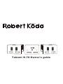
1
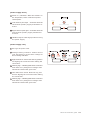
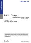
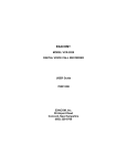
Left Channel
Off
On
Right Channel
Takumi K-70 DC Reactor Power Supply
Takumi K-70 Owner's guide
Contents
1. Introduction
T1 Fuse replacement
2. Brief description
T2 Tube replacement
3. Getting to know the parts
T3 DC cable adjustments
4. Placement and Layout
T4 AC voltage adjustments
5. Power requirements
Sections T1 thru T4
provide information specifically
for qualified and authorized
service personal.
Do not attempt these adjustmets!
6. Connecting and set-up
7. Powering up
8.
Powering down and disconnection
A1 On driving loudspeakers
9. Maintenance and cleaning
A2 On power supplies
10. Trouble shooting
A3 The meaning of “Takumi”
11. Conditions of warranty
12. Specifications
Section A1 thru A3
are included for aditional
interest only.
1. Introduction
2. Brief Description
Congratulations on your acquisition of the
Takumi K-70 power amplifier system. This is a
truly special amplifier and due to several
uncommon attributes, complete study of this
manual is necessary before proceeding with the
installation of the K-70. We would like to
acknowledge your purchase and extend our
hand in gratitude.
The Takumi K-70 power amplifier system is
delivered in a three chassis format, a pair of
mono amplifiers and a single, separate power
supply unit. As a variant of the single ended
amplifier family line the K-70 generates a
great deal of heat, even when coasting at zero
volume. This amplifier makes use of six vacuum
tubes and sixty eight power transistors, all
woven together in a unique and marvellous form.
Given suitable installation, the K-70 will provide
years upon years of illuminated and
exhilarating listening sessions.
Thank you again for your choice of this Robert
Koda product.
Some of the key features that make this
amplifier spectacular include:
●
Cordially,
The Robert Kŏda Team.
●
●
●
IMA
LT
U plifile
m
A
●
The ability to extract total performance
from the loudspeakers by being able to drive
the loudspeakers. We invite you to review
section A1 to gain a fuller understanding of
our interpretation and the importance of
drive.
A flexible and versatile input arrangement
where various inputs including voltage
mode and current mode, single ended or
balanced may be inter-changed with out
compromise.
Freedom from “power supply” sound. Not
just by building a “bullet proof” power supply
but by removing the very interaction between the power supply and the amplifier
proper, we have solved an important issue
well known to blemish an amplifier’s sonics.
Flexible tripple chassis layout arrangement
to facilitate short cable runs.
A critical selection of parts, internal wiring
and layout to extract the finest possible
result.
And of course, the Sound !
Takumi K-70 Owner's guide
1/2
3. Getting to know the parts
Balanced
L
J
K70’s DC power supply. Note the key position
for aligning the connector when making the
connection.
K
Hi-Z
and cable carry dangerous voltages and
should be treated with great care.
SE
Type 5842
Lo-Z
H
BAL
F
Type 5842
B Warning sign – indicating that the DC connector
INPUTS
A DC power connector for connection to the
Single Ended
(Mono amps)
G
I
Made in Japan
C Positive speaker terminal.
D Negative speaker terminal.
E Cautionary sign – The speaker terminals are
floating at a DC potential and connection
precautions must be fully understood before
making connections!
Takumi K-70
B
F Vacuum tube – Triode type 5842
A
G Vacuum tube – Triode type 5842
H Hi-Z / Low Z switch. The general setting is
Hi-Z
C
DC POWER INPUT
SPEAKER
+
I Balanced / SE select. Set to correspond with
the connector you hook up to.
Caution. Risk of
electrical shock.
Do not open.
CAUTION!
E
Serial number
-
DC FLOATING.
See manual before making connections.
J XLR type balanced input. Pin 2 wired “Hot”.
K Interphase transformer. This devise may be
removed and replaced with the optional
types for use with current mode input
sources or other possible configurations.
L RCA single ended input socket.
3
Takumi K-70 Owner's guide
D
(Power supply front)
A Power on / off switch. When the switch is in
the off position, there is almost no power
consumption.
Left Channel
On
A
B Left channel pilot light – Indicates that the
B
left channel primary supply transformer is
active.
C
Off
Takumi K-70 DC Reactor Power Supply
Right Channel
C
D
Right channel pilot light – Indicates that the
right channel primary supply transformer
is active.
D Handles. May be used as grips when moving
the power supply.
(Power supply rear)
A IEC type AC power inlet.
B Voltage setting indicator. Please ensure
your AC supply is of the same voltage as
this marking indicates.
C Right channel DC outlet. Note the key position
for aligning the connector when making the
connection.
D
C
B
230V
F
A
E
D
D Warning sign – indicating that the DC connector
and cable carry dangerous voltages and
should be treated with great care.
E Left channel DC outlet. Note the key posi-
tion for aligning the connector when making
the connection.
F Warning sign – indicating that the DC connector
and cable carry dangerous voltages and
should be treated with great care.
Takumi K-70 Owner's guide
3-2
4. Placement and layout
The triple chassis configuration adopted in the
K-70 allows extra flexibility in the layout possibilities for your rig.
The pair of mono amps are designed to be placed
on the floor or better, on a gorgeous plinth to
enhance beauty and provide subtle but worthwhile sonic improvement. By no account should
these amplifiers be located in a concealed space
as the heat build-up will shorten the amplifier’s
life. Please be sure about this as such damage
is not covered under guarantee.
The mono amps may be placed in the general
mode, with the vacuum tubes and connectors
facing downward and the edges of the two thick
aluminium plates forming the amplifier’s “feet”.
The whole unit may then be rotated 90 degrees
or even 180 degrees to assist in getting the
neatest or shortest cable runs between the
amplifiers and loudspeakers.
4 Takumi K-70 Owner's guide
As an alternative, the amplifiers may be placed
in the inverted mode where the vacuum tubes
and excreta become visible. This mode may further
reduce cable lengths and certainly allows for
easier connectivity.
If you choose the inverted mode, please use the
four feet provided to lift the amplifier off the
support structure.
The feet are important
because they prevent the top (now bottom)
from being scratched, promote essential cooling
and cut down vibration. Bear in mind that as
the vacuum tubes become fully exposed in the
inverted mode and since these devises get hot,
are fragile and use high voltages, this mode
may not be suitable for all environments
particularly those with children and pets about.
Installation
the feet
instructions
for
when the amplifier is used in
the inverted position.
Note the twelve hex screws holding the top
cover onto the main amplifier chassis. Looking
at each line of four screws, remove the central
two screws only from each row such that a total
of four screws have been removed.
Place the feet into position with the flat side of
the foot sitting on the amplifier. Use the four
long hex screws provided to secure the feet /
cover to the amplifier’s chassis.
Note: The power supply is not designed to stand
inverted and so the feet are not used in this
fashion with the power supply unit.
If you would like to use the feet with the
amplifier’s mounted in the standard position,
simply lift the front / rear and let the faceplate
rest in the groove of the foot. Such may also be
used with the power supply unit.
Takumi K-70 Owner's guide
4-2
DC supply
It should be comforting to know that those long
power cables connecting the power supply to
each mono amplifier do not disturb sound
quality. Feel free to place the power supply unit
at any distance from the mono amps. Should
you require a custom length of DC power cable,
we will be delighted to build that for you.
The power supply generates moderate amounts
of heat and requires good ventilation space. If
insufficient ventilation is provided, the internal
thermal fuses in the transformers may melt and
the transformers would need to be replaced.
Not wishing this to occur we have also placed a
thermal switch in the heart of the power supply
that will shut down the power supply if the
chassis becomes too hot.
Another consideration to be addressed is one of
mechanical vibration. The magnetic components in the power supply “purr” along as the
unit is delivering well over one horse power
from the moment you turn the power on. Good
placement and perhaps the use of a dedicated
audio stand, isolating and lifting the unit well
clear will be of great benefit.
DC reactor simply explained: Our power supply uses
eight power inductors to store energy in the form of
a magnetic field. Such inductors are called DC
reactors and hence the name. One aspect to be
aware of though, is that magnetic “spillage” may
induce a buzzing sound into other magnetic sensitive components so we advise – Do not place your
turntable on top of the DC supply!
On another note, one other highly respected amplifier manufacturer* notes:” Their use in power amplifier supplies is an indication that the manufacturer
has an unusually strong commitment to performance.” We think so too!
*Nelson Pass with kind permission.
4-3
Takumi K-70 Owner's guide
Placement cautions.
Locations of high humidity, dust and plentiful
sunlight are not recommended for any of the
K-70’s components. Also take care to place the
units such that water / liquids and other objects
may not spill into the electronics! Beachfront
accommodation is not recommended for the
K-70 as salt build up, combined with the heat
moisture may dramatically reduce life span.
5. Power requirements
While the K-70 does not require a particularly
clean AC power source to operate at its best, it
does consume about 900W from the moment
the power switch is turned on. This amounts to
a current draw of about 4 or 5 amps for 220 to
240V models and twice that for 100 to 110V
models.
Please note that this unit is NOT auto voltage
selecting! Use only an AC source of a voltage
that corresponds with the AC voltage setting of
this amplifier – clearly marked on the back of
the DC power supply unit.
AC power cable
This amplifier is not supplied with an AC power
cable.
The AC cable used with this amplifier should be
rated at 10 amps or greater,
must be earthed and comply with the safety
standards of the country where used.
If you have any doubts or concerns regarding
suitable AC power cables, please
consult your local distributor.
Takumi K-70 Owner's guide
5
6. Connecting and set-up
(Mono Blocks)
It is essensial that the K-70 is powered off completely before wiring or re-wiring.
Speakers
Important notice: The K-70 has DC floating
outputs. This means you need to take some
special precautions otherwise you may destroy
the loudspeakers you have connected.
The precautions are really very simple.
●
●
Never allow one of the speaker wires to touch the
chassis work of the K-70 or any other conductive
object other than the K-70’s speaker terminal.
Only connect passive loudspeakers to the speaker
terminals. This means that any devise or loudspeaker that has its own AC power chord, such as
active subwoofers and loudspeakers with internal
active subwoofers, may NOT be directly connect
ed to the K-70. If you have an enquiry in this regard, we will be happy to assist before you make
the connections! Electrostatic loudspeakers
also fall into the category of not connectable
but under certain circumstances, depending on
make and model, may be safely connected.
If your speaker cables are of a stiff nature, it may
be a good idea to provide some strain relief to
allow the cable ends to be correctly fastened into
the K-70 speaker terminals such that the chances
of a speaker wire jumping out and touching the
K-70's chassis are minimised.
Source component connection.
The K-70 has four input modes; Single ended and
Balanced voltage driven, plus Single ended
and Balanced in the current mode.
Current mode pre-amplifiers are presently
rare so most installations would use the practically universal voltage mode.
You can choose between using the single
ended or balanced inputs with confidence. The
best performer will be dictated only by your
source components characteristics.
6
Takumi K-70 Owner's guide
Connect either to the balanced or single ended
input socket But not both at the same time! Set
the Bal/SE switch into the appropriate position
and set the Low- Z / Hi-Z switch into the Hi-Z
position. These are locking switches to prevent
accidental adjustment. Simply lift the lever of
the switch toward you and then toggle it to the
selection required.
Note – Don’t adjust the switches or make
connections while the amplifier is on!
Recommendation – If you live in an area where
the atmosphere is corrosive, it may be wise to
shelter un-used input sockets from the environment by plugging in a “dummy” connector or
other socket protection caps.
For reference: The balanced input is wired as
follows: Pin 1 is Ground, Pin 2 is Hot and Pin
3 is Cold.
Using Current Mode inputs
For the current mode inputs to work correctly the
K-70’s input interphase, mounted on an octal
socket between the two vacuum tubes needs to
be swapped out for a different one. This unit is
available as a separate accessory.
DC Power connector
The DC power connector connects each mono
unit to the power supply.
We have used connectors here of military application origin (that should explain their color!) since
the connectors carry some 11 amps of continuous current and a high 350 volts.
Align the key of the connector with the key of the
socket, push until the connector and socket meet
and then rotate the connector’s outer ring until
the connector fully locks into the socket. There is
quite a bit of thread so it takes a little effort!
We have used a right angle connector on the
amplifier side and a straight connector on the
power supply side. If you find that the right
angle connector is protruding in an inconvenient
direction, it is possible to adjust this – Please
see the technical section T3 for details.
Note – The power supply will not switch on
unless all DC power connections are made for
both amplifiers. We have done this to contribute to safety.
Connecting in the power supply
It may be most practical to first make DC cable
connections to the main amplifiers.
Next connect up the DC cables to the power
supply and finally, make the AC connection. May
we remind you that the AC power cable must be
earthed for safety reasons.
Also always remember that the DC cables carry
lethal power. If any part of the connector or cable
appears to be damaged, please return the cable
to your distributor for replacement.
7. Powering up
Before the moment of powering up, it’s a good
idea to do one more check – All connections
good, all switches in the correct position.
Vacuum tubes nice and snug in their sockets.
OK. The factory set voltage of the power supply
corresponds to your AC supply voltage? OK.
Grab the rotary power switch on the power
supplies front panel and turn it onto the On
position. You should be greeted by the warm
illumination of two amber neon lights. The
power supply will purr and there may even be a
few “clicking” sounds during the first few seconds.
But no sound should emanate from the loudspeakers. If nasty sounds do emanate from the
loudspeakers, power down immediately and
seek advise from the trouble shooting section.
If all is good, the tubes will reach operation
within 60 seconds and its time to settle down to
your first musical journey with this wonderful
amplifier but keep an occasional eye on things.
It is wise to check the temperature of each
mono amplifier’s heat sinks as well as the power
supply’s temperature. The power supply should
be warm to the touch with the front panel,
particularly around the neon lights being
notably warmer. This is not due to the lights but
rather the power diodes bolted onto the inside
of the panel.
The left and right heat sinks on each mono amp
will be at a somewhat different temperature.
You wouldn’t want to leave your hands on them
all day but if it feels like they are burning you,
then the amplifiers need to be re-located to
provide better cooling.
Important – The K-70 warms up to optimal sound
quality levels within an hour or so. Do not leave
the amplifier on needlessly and do not forget the
unit on whilst not under your direct supervision.
8. Powering down and disconnection
Powering down is straight forward; simply turn
off the power switch. However, should you want
to power up again, please wait at least one minute
before doing so. Quick repetitive toggling between
on and off can upset or damage the vacuum tube
power supply.
Note:The short time lag between turring the
unit off and the actual swith off is normal.
Disconnection
First turn off the unit and then remove the AC
power cable. Wait at least 5 minutes before
continuing with any further system disassembly. This gives the vacuum tubes opportunity to
cool down and the condensers time to at least
partly discharge their energy.
9. Maintenance and cleaning.
Before undertaking any cleaning operation, the
system should be powered down and allowed to
fully cool. To be safe, remove the AC power
cable from the DC power supply.
The finned heat sinks are best cleaned with a
paint brush with very long hairs for reaching the
deep crevices. Treat cleaning with an air brush
with great care as they are capable of blowing
the dirt and dust into places where these matter
would not be appreciated, like circuits and junctions, where cleaning then by degrees only
becomes more difficult.
Chassis work may be dusted first with the
above mentioned paint brush and further
cleaned with a soft cloth, moistened with a
solution of warm water and a very mild mix with
soap or dish washing liquid.
Maintenance - General.
In general no maintenance is required. Of
primary concern is the operating environment
the K-70 is placed in as, if ill placed, the otherwise very long life-span of this machine may be
compromised.
Two specific areas of maintenance however
include the vacuum tubes and fuses.
These parts however are not user serviceable
and their replacement should only be undertaken
by suitably qualified persons.
Takumi K-70 Owner's guide
7/8/9
Maintenance-Fuses
After many cycles of use, the fuses may melt
simply because they have weakened over time.
To avoid this from occurring at an inconvenient
time, we recommend a bi-annual fuse replacement.
Important – Do not use anything other than the
prescribed fuse of identical rating. Be absolutely
sure to put the correct fuse into the correct
socket. If a fuse has melted and the subsequent replacement melts immediately after
replacement, disconnect the power supply from
the AC supply swiftly and make preparation as
the K-70 will need professional help.
Vacuum tubes
How long do the vacuum tubes last? It’s rather
like the proverbial question, “How long is a
piece of string?”. But we will try to shed some
light onto this topic. Generally the tubes in the
K-70 will last a very long time. This is because
they are operated conservatively (not driven
hard) and they are excellent tubes to begin
with. A very long time depends on how much you
use the amplifier but based on a calculation of
three hours use daily, we estimate five to twenty
years and quite probably 20 to 50 years for the
rectifier tubes. But, as things go, unexpected
failures do occur and they can occur at any time.
In the event that a tube needs to be replaced it
is paramount that the tube is replaced only and
ONLY with the same part in the case of the
K-70. These tubes are: Type 5842 for the mono
amplifiers, two pieces each and Type 6X5 for
the power supply, two pieces. Tube swapping
for other types is forbidden in the K-70 and not
only invalidates the warranty but is almost
certain to cause permanent damage to the
amplifiers and loudspeakers. Please be careful!
9
Takumi K-70 Owner's guide
The type 5842 tubes include the 417A
tubes family and the more obscure
model denomination F-55788. Selections from Amperex, Raytheon, Tungsol
and the ever-popular Western Electric
with their 417A offering, all offer a
range of alternatives. The Raytheon
5842 is selected for shipping with the
K-70 due to its original military target
market requiring hardier tube units and
for Raytheon’s strong sonic performance. We will be pleased to assist if
you need further advice on the topic of
vacuum tubes.
On the subject of liquid tube enhancers, judicious
regard should be given to the use of these potions
and each behave with characteristic dissimilarity
so it is difficult to generalise any concern. Some
liquids may age and harden over time and affect
variances in tube contact performance. It would
be up to the individual listener if this is a required
result. Some liquids deal with the micro-fissure
aberrations of a tube’s pins and may, themselves,
be conductive in nature in order to do so. Should
these conductive materials be smeared accidentally to areas between the pins then short circuiting across the pins may occur. What ever you do,
don’t bend the tubes pins as this can compromise
the vacuum within the tube and render the devise
sadly dysfunctional.
10. Trouble shooting
One or more neon not lit.
In this case at least one channel will not be
producing any sound and the corresponding
fuse has melted.
The power supply suddenly turned off.
The DC power supply is equipped with thermal
detection. If the sensor location exceeds 70
degrees, the power supply will automatically
turn off and switch back on again when the
temperature drops by about 20 degrees.
Both neons are lit but there is no sound.
It is possible the fuse for the vacuum tube part
of the amplifier is melted and requires
replacement.
A buzzing sound can be heard from one
or both speakers.
The sound has disappeared on one or
both channels but all indicator lights are
still operational.
Each mono block has thermal sensors coupled
to both the left and right flank heatsinks.
If the amplifier is too hot, then the thermal
Power down the amplifier and remove the
sensors will trigger and shut down only the
sources’ interconnect cables from both mono
heat generating portion of the amplifier.
amplifiers such that the amplifiers are only
Normal operation will be restored automatically
connected to the loudspeakers and the DC
once the temperature has dropped by about 20
power supply. Power up again and check the
degrees.
buzzing sound. If the sound has disappeared
then the source of the problem is either
If thermal triggering has occurred, the
source component / pre-amplifier related or
amplifier(s) should be re-located for better
as a result of something called a ground
cooling.
loop. The best way to cure the ground loop
problem is to use the K70’ s balanced inputs,
driven by a balanced source.
A buzzing sound can be heard from the
DC power supply.
This is normal but if you have noticed a recent
increase it could be due to several possibilities.
The positioning of the power supply in
relationship to hard surfaces and room
modifications as well as listening position all
have some affect. If these conditions have not
changed but the power supply has become
really noisy, there is a chance that one of the
transformers or chokes is miss-behaving and
professional help will be needed.
A big crackling sound came from the
speakers when I turned the amplifier on.
Check that one of the speaker wires has not
become adrift and made contact with the
amplifiers chassis. When this occurs, massive
DC is passed into your loudspeaker and this
DC will almost certainly damage the
loudspeaker’ s woofer.
Takumi K-70 Owner's guide
10/11
11. Conditions of Warranty
The Robert Kŏda Takumi K-70 is guaranteed
for one full year from date of purchase, parts and
labour, against any breakdowns or component
failure.
Failures after this period will be treated on a
case by case basis and we will carefully examine
the circumstances with an aim to keep repair
costs out of the customer’ s pocket.
Conditions of use
Robert Kŏda LLC Japan disclaims any responsibility in case of damage or injury directly or
indirectly due to any misuse, incorrect manipulation, or non-observance of red warnings and/or
advice formulated in this entire manual.
Any unauthorised intervention on or in the
Robert Kŏda Takumi K-70 or any failure due to
one of the situations described above will
render this warranty void.
Assistance
If you have any difficulties, enquiries or simply
suggestions, please feel free to contact us by
e-mail at:
[email protected]
We welcome mail correspondence and our
address is:
Robert-Kŏda LLC
1-9-4 Azusawa
Itabashi-Ku
Tokyo
174-0051
Japan
Now that we have reached the end of the
general manual (those so inclined may like to
proceed to the technical section), we would
like to wish you countless hours of sheer
musical pleasure with your new Takumi –
K-70 amplifier.
In fidelity,
Robert Leslie Koch
11
Takumi K-70 Owner's guide
12.
Specifications
DNA
Single Ended Class A1 hybrid power amplifier
with separate power supply.
Output power
Approximately 70W. Power delivery maximised
for 3 to 7 ohm loads.
Gain
Input impedance
Output impedance
Signal to Noise Ratio
Power response
Power consumption
Size
Weight
Operating environment
25.5dB SE in or balanced in, voltage mode.
10V/mA in current mode.
30K Ohms, Voltage mode, 50 ohms current
mode.
Less than 0.07 ohms 20 Hz to 20Khz.
Greater than 115dB A weighted at nominal
output.
Less than 5Hz to greater than 200KHz.
900 Watts at any volume into any load.
380mm wide, 256mm high, 500mm deep
(each of 3 units)
Power supply: 40Kg
Mono amps: 20Kg each
Operating temperature 0 to 35 degrees Celsius.
Altitude sea level thru 3000m above sea level.
Storage temperature –20 to +50 degrees Celsius.
Specification subject to change without notice. 12
T1. Fuses
T2. Tube replacement
To prevent fire and unsafe conditions in event of
failure, replace fuses with only those indicated.
All fuses are 3AG type, 31.8 by 6.4mm size, slow
blow types. Fuse rating and function are as
follows:
Fuse. Region 220 to 240V
A
B
C
D
6A, 250V
200mA, 250V
1A, 250V
6A, 250V
Region 100 –120V
10A,
400mA,
2A,
10A,
125V
125V
125V
125V
Functions
A
B
C
D
Right channel high current supply.
Vacuum tube supply.
Solid state relay driver power supply.
Left channel high current supply.
All fuses are located in line with the primary
windings of their respective power transformers. All system fuses are located in the DC
supply unit and may be accessed after
removing AC power and the unit’s top cover.
We have carefully selected these tubes for use
in the K-70. While there may be noticeable
differences between different brands of the
same tube type, tube type swapping is not
recommended.
The type 5842 vacuum tube may only be
replaced with a type 5842 or 417A. Failure to do
so will result in damage to both the amplifier
and possibly, the attached loudspeakers.
The 6X5 might be replaceable with variants, not
of identical type but ONLY at the owner’s risk.
We categorically specify type 6X5 / CV574 for
the use in this product and use of any other
tube will render the warranty void. Since the
equipment has been modified, safety compliance may not be satisfied. For technical interest
only, the 6.3 volt filament supply for the rectifier tube is capable of delivering up to 3 amps.
T1/2
Takumi K-70 Owner's guide
T3. DC cable configuration.
The cable itself is four-core each of a 3.5mm
diameter and the cable overall 600V rated and
double sheathed.
Colour assignment is:
Red; 350V line @ 50mA.
Green; ground return and chassis earth.
White; Negative 32V line at 11 amps
Black; return line for white. This cable
connects to chassis only at the amplifier end.
DC connector adjustment.
Unscrew the collar and slide it down the cable.
It may be desirable to adjust the DC connector
terminating onto the power amplifier such that
the right bend faces a different degree. This may
be accomplished as illustrated.
The cable can be quite heavy and the connectors
a little slippery so it might take a few moments
to re-assemble the connector. Important: Ensure
there is no undue strain that might compromise
termination of the wires onto the connector pins.
The sides should now freely drop away.
Loosten the
cable clamp.
Unscrew the cable clamp and slide
Re-atatch the sides to direct the required cable
it down the cable.
degree.
Replace and secure parts. Note the new key
position.
Takumi K-70 Owner's guide
T3
T4. AC voltage adjustment
If the amplifier needs to be set for a different
country’s AC voltage system, this may be
easily undertaken by qualified personnel
whom follow necessary precautions.
Unplug the DC supply completely and allow 5
minutes cooling time.
Turn the DC supply upside down and place it on
a suitable non scratch surface.
Remove the bottom cover and locate the PCB as
shown.
120V operation
Bridge Orange / Blue.
Bridge White / Black.
Fused AC to Blue.
240V operation
Bridge Orange / Black.
Fused AC to Blue.
Double check your work and ensure all contact
have been fully secured.
Remember to replace all four fuses (the top
cover will need to be removed) with the correct
rating for the new AC voltage selection.
The rear panel must be relabled to indicate
the new AC voltage!
DIP switches
There are three groups of terminal connectors,
one for each power transformer. The blue transformer mounted on the PCB will not require any
adjustments.
All that is required is to place the jumper tabs
into the correct position and direct the fused AC
wire onto the correct position. Obviously this
operation needs to be repeated in the same way
for each of the three groups. The fused AC wires
can be swiftly identified since they are the only
black wires with a RED heat shrink tube around
the termination area.
Setting the DIP switches
DIP switches 1 thru 4’s position should be set
according to the AC mains voltage used.
Failure to set the switches correctly will result in
improper turn on / off sequence of the power
supply.
For 220 to 240V
SW1 ON
SW2 OFF
For 110 to 120V
SW1 OFF
SW2 ON
SW3 and 4 are indifferent.
T4
Takumi K-70 Owner's guide
A1. Driving loudspeakers
Set your speakers free!
Our finding is that a critical attribute of an
amplifier is one of the ability to drive the load the loudspeakers. If loudspeakers were resistors then the perfect amplifier would have
existed many years ago. But loudspeakers are
not resistors, they are what is known as
reactive. Reactive defines a condition where the
electrical currents and voltages become missaligned and are no longer simultaneous. And
this happens all the time…
Broadly, the more drive units, the more crossover parts, the more reactive the loudspeaker,
and the less chance an amplifier has of extracting the speakers true sonic potential. Yet even
a loudspeaker with a single drive unit and no
crossover is reactive. Each miniscule ripple in
it’s response being correlated with a reactive
shifting. A reactive shifting who’s effect tricks
the amplifier and is finally mirrored in a
distorted way in the power supply.
The K-70 is a seventy watt amplifier with a peak
current delivery of perhaps 7 or 8 amperes yet
it drives the most difficult loudspeakers to their
peek performance with glee while other amplifiers, capable of delivering twenty times the
power might not. What is going on here?
Well, there are two separate and independent
issues that have always been rolled up into one
(AKA the power to Drive); the ability to evoke
sound quality from a loudspeaker, and the
ability to produce enough loudness before the
amplifier reaches its limit where the loudness
cannot be exceeded.
Looking at the second part first, is seventy
watts going to get your speakers to go loud
enough? This depends on your definition of
loud, your loudspeakers sensitivity (a measurement of how much noise it makes if you give it
one watt), the efficiency of your room (how
much sound produced by the speakers will
actually reach your ears) and finally the
ambient background noise level (a drop of a
magazine in a library can draw a lot of attention!). Just to add a little more uncertainty to
the equation, it also depends on how quickly the
amplifier recovers when subject to bursts of
clipping. If the amplifier recovers well then a
burst of clipping distortion will pass you by
without you even being aware of it!
Taking a broad spectrum of home music listening environments, personal tastes and loudspeakers having a sensitivity of 84 to 90dB /
Watt, we conclude that with our amplifiers, 10
to 100W will cover the most demanding situations rather comfortably.
What about the ability to drive the loudspeaker?
It is commonly understood that this term
implies that the amplifier will be stable (safe)
with a reactive load, and produce hundreds
of amps into a one ohm load (excreta!) but
our appreciation is one of where the amplifier
is able to control the load. How do we do this?
By developing the correct amplifier architecture.
This is the key difference between the K-70 and
other amplifiers and the overwhelming reason why
the K-70 will set your speakers free!
A2. Getting rid of the
Sound of the power supply.
Set your amplifier free!
Another major advancement the K-70 has
made is getting rid of the sound of the power
supply and it certainly is a sonic blessing!
Just like the amplifier has to drive the
reactive loudspeaker to achieve sound purity,
the power supply has to drive the amplifier
with equal finesse.
It just so happens that the reactiveness of
the loudspeaker is mirrored into the power
supply and this is the bulk of the two main
reasons why the performance quality of a
power supply has such great affect on final
sound quality.
The other reason of far less significance is that
the power supply always carries a residual
noise and this can pass into the amplifier and
finally affect the amplifiers noise floor. But in
reality, the noise floor is actually determined
by your listening environment – Unless you
live very quiet place!
Robert Koda eliminated the vile power supply
sound by not only building a power supply of
exceptionally low residual electrical noise
(our unit does purr along but that is
s o met hi ng comp l et el y d i fferent) , b ut b y
building an amplifier that “looks” , well like a
resistor! So the power supply never feels the
impact of the loudspeaker and the link is
simply eliminated.
Dynamic simplicity, this has been our quest!
The concept seems simple enough! So why
don’ t other manufactures build amplifiers that
just look like a resistor to the power supply
driving them? One probable reason is the
failure to completely appreciate the
significance of what is happening to the music,
another the huge cost of implementing such
circuit topologies. Another, dare we say, it
requires creativeness and a will to go much
further than an extra mile.
Takumi K-70 Owner's guide
A1/2
The meaning of "Takumi"
The meaning of the Japanese character “Takumi”
can be translated as “Maestro”.
Our brand endeavours to build a product in the
spirit of Maestro.