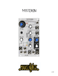
1
EXCIMERLASER
ESIRIS
SERVICE MANUAL
Schwind GmbH
Mainparkstrasse 6-10
D-63801 Kleinostheim
SERVICE MANUAL
2
of
79
___________________________________________________________________________
_______
ESIRIS - Version 1.0
Date: 22.09.00
SERVICE MANUAL
3
of
79
INDEX
PAGE
1. SECURITY OF DEVICE (LASER BEAM) ........................................................................................... 5
GENERAL ................................................................................................................................................... 5
Alarm Shields and Type Shield............................................................................................................ 6
Accessible Beam Area......................................................................................................................... 7
Protection Glasses............................................................................................................................... 7
Working Gas ........................................................................................................................................ 8
Gas containment:................................................................................................................................. 8
DECLARATION OF MANUFACTURER (MPG)...................................................................................... 9
2. DESCRIPTION .................................................................................................................................. 10
SPECIFICATION ........................................................................................................................................ 10
EXCIMER-LASER ...................................................................................................................................... 12
GAS SUPPLY ............................................................................................................................................ 13
GASCONTAINMENT: .................................................................................................................................. 13
DELIVERY SYSTEM ................................................................................................................................... 14
MICROSCOPE AND ILLUMINATION .............................................................................................................. 14
CONTROLLING .......................................................................................................................................... 15
PATIENT BED ........................................................................................................................................... 15
FOOT SWITCH .......................................................................................................................................... 15
RINSING OF OPTICAL BEAM DELIVERY SYSTEM ......................................................................................... 15
3. INSTALLATION REQUIREMENTS AND PREPARATIONS............................................................. 17
W ORKING ROOM ...................................................................................................................................... 17
DIMENSIONS ESIRIS................................................................................................................................ 18
INPUT REQUIREMENTS ............................................................................................................................. 19
INSTALLATION AND ROOM PREPARATIONS FOR THE INSTALLATION............................................................... 20
Minimum room dimensions (or room requirements) .......................................................................... 20
FLOOR REQUIREMENTS ............................................................................................................................ 20
INSTALLATION REQUIREMENTS ................................................................................................................. 20
Laser warning lamp ........................................................................................................................... 21
Dimensions of boxes for the delivery................................................................................................. 21
DELIVERY ................................................................................................................................................ 22
4. SOFTWARE DESCRIPTION BY SERVICE LOGIN.......................................................................... 23
MENU EXTRA ........................................................................................................................................... 23
Menu Logfile ...................................................................................................................................... 23
Menu Parameter ................................................................................................................................ 24
Distributor adress............................................................................................................................... 25
MENU SERVICE ........................................................................................................................................ 27
Menu Laser:....................................................................................................................................... 29
Menu Scanner: .................................................................................................................................. 35
Menu digital inputs / outputs .............................................................................................................. 36
Gascontainment:................................................................................................................................ 39
MENU ADJUSTMENT:................................................................................................................................. 40
Laser:................................................................................................................................................. 40
MENU TECHNICAL SECUTITY CHECK (TSC)............................................................................................... 44
5. UNPACKING AND CONTROLLING ................................................................................................. 45
PUTTING INTO OPERATION ........................................................................................................................ 46
W ARRANTY .............................................................................................................................................. 47
6. DISMANTLING OF THE ESIRIS-LASERS ....................................................................................... 48
___________________________________________________________________________
_______
ESIRIS - Version 1.0
Date: 22.09.00
SERVICE MANUAL
4
of
79
REMOVAL OF GAS BOTTLES (PREMIX AND HELIUM) ..................................................................................... 48
6.2 UNPLUG ELECTRICAL CONNECTIONS OF PATIENT BED, CAN-BUS MODULE AND GASCONTAINMENT ........ 52
6.3 DISMANTLING OF OPTICAL PARTS ........................................................................................................ 54
Dismantling of microscope :............................................................................................................... 54
Dismantling CCD camera tower: ....................................................................................................... 55
Dismantling Scanning mirror.............................................................................................................. 57
NITROGEN GAS CYLINDER................................................................................................................ 59
DISMANTLE MONITOR AND KEYBOARD.......................................................................................... 59
DISCONNECTION OF THE FLUENCE DETECTOR............................................................................ 61
DISMANTLING THE PATIENT BED ............................................................................................................... 61
DISMANTLING LASER ................................................................................................................................ 62
7 INSTALLATION OF THE ESIRIS-LASER ......................................................................................... 63
ASSEMBLING THE LASER .......................................................................................................................... 63
ASSEMBLING OF THE PATIENT BED ........................................................................................................... 63
ELECTRICAL CONNECTION OF PATIENT BED, CAN-BUS-MODULE AND GAS-CONTAINMENT. ........................ 66
ASSEMBLING OF MONITOR AND KEYBOARD ............................................................................................... 67
ASSEMBLING OF THE LASER BEAM DELIVERY SYSTEM ............................................................................... 68
Assembling the Microscope:.............................................................................................................. 68
Assembling CCD-Camera Tower ...................................................................................................... 69
Assembling the Scanner.................................................................................................................... 70
CONNECTION OF THE NITROGEN BOTTLE .................................................................................................. 70
ASSEMBLING FLUENCE DETECTOR............................................................................................................ 71
CONNECTION OF THE GAS MANAGEMENT TO THE OPTEX LASER ................................................................ 71
8. ALIGNMENT OF THE ESIRIS........................................................................................................... 73
APPENDIX ............................................................................................................................................. 74
APPENDIX A: CALCULATION BASIS ............................................................................................................ 74
A1. Introduction.................................................................................................................................. 74
A2. Correction of Myopia ................................................................................................................... 75
APPENDIX B: BEAM DELIVERY SYSTEM ..................................................................................................... 76
B1. Optical System ............................................................................................................................ 76
___________________________________________________________________________
_______
ESIRIS - Version 1.0
Date: 22.09.00
SERVICE MANUAL
5
of
79
1. Security of Device (Laser beam)
General
The SCHWIND ESIRIS is working with a pulsed UV-Laser. The Laser belongs to
class 4, which is the one with the highest danger potential. In any case, exposition of
eye or skin through direct or scattered laser beams has to be avoided. A professional
instrument maintenance - done in the planned intervals - secures that unintended
beams can not be exposed of the unit.
Opening of the device is only allowed through trained technicians. All persons,
assisting the treatment or attending the procedure have to be informed about danger
potentials and have to wear protection glasses.
Besides the high-performance laser, the SCHWIND ESIRIS uses three diodelasers
as positioning and fixation device. The output of the fixation laser is below 10 µW.
Therefore it belongs to class 1, which allows an undefined exposition time of the eye.
The positioning lasers are used to adjust the exact working distance to the corneal
surface. Their output is 50 - 100 µW. As the beams are aimed in a angle to the eye,
an influence at the retina is impossible.
Warnings Laser beam
The laser emits high-performance beams:
Wave lengths:
193 nm
Pulse energy:
max. 8 mJ
Energy density:
800 mJ/cm2
Laser beams with these data are potentially dangerous, but in our case, possible
danger is minimised through some details:
•
the beam diverges after passing the ablation area, so only in this area a high
energy density exists.
•
the beams are partially absorbed in the air
•
the cornea does not reflect beam during treatment
These effects reduce the energy density of the beam quickly with growing distance to
the working area, which is about 280 mm under the beam output opening. In spite of
this, the following warnings have to be followed for a safety use:
___________________________________________________________________________
_______
ESIRIS - Version 1.0
Date: 22.09.00
SERVICE MANUAL
6
of
79
•
Never look into the laser beam!
•
Never put your skin into the laser beam!
•
Wear protection glasses
•
Make sure, that no reflection devices are placed in the area of the
laserbeam
•
Follow the instructions of the trade association VBG 93!
•
Persons, not used with the lasers, have to be informed about possible
risks!
Alarm Shields and Type Shield
Beam output is marked with laser warning signs..1.2. Warnschilder
They are looking as following:
___________________________________________________________________________
_______
ESIRIS - Version 1.0
Date: 22.09.00
SERVICE MANUAL
7
of
79
Accessible Beam Area
The beam area of the device is horizontal down from the output opening to the next
surface. Normally this is the patient bed or, in case of treatment, the patient eye.
Diameter of beam at the output opening is app. 1,0 mm. In the treatment area, which
is 290 mm under the output opening, the beam has a diameter of 1,0 mm. Output
and energy density of beam decreases accordingly with increasing distance from
treatment area.
Protection Glasses
All persons inside the room (except the patient) have to wear protection glasses
according to DIN EN 207, when the laser is working. These glasses must have
protection level 7 for beams of 193 nm. The operating surgeon can put-off the
glasses, when he looks through the microscope. The glass optics of the microscopes
weaken the laserbeam, so that the necessary protection level is achieved. Protection
level of glasses depends on maximum existing middle output density (at max. pulse
following frequency) or the maximal energy density. These values are 5 x 10² J/m2.
___________________________________________________________________________
_______
ESIRIS - Version 1.0
Date: 22.09.00
SERVICE MANUAL
8
of
79
Working Gas
Danger through the working gas (fluoride 0.106 %, argon 3.33 % and neon 96.56 %)
has not to be feared.
The laser head contains only a small quantity of fluoride. It is checked according to
the pressure containment regulations. An unintentional output of working gas is very
unlikely. Fluoride can be recognised through its pungent smell, long before the
concentration will come to maximum allowed values for working places. In such
case, open the window, leave the room and call service department of your
distributor or directly
Gas containment:
Pressure gas bottle with working gas is stored inside a gas containment. This gas
containment is airtight and has a filter, which would absorb the fluoride in case of a
leak. For service demands, there is a pressure gas bottle with helium, stored inside
the gas containment too.
___________________________________________________________________________
_______
ESIRIS - Version 1.0
Date: 22.09.00
SERVICE MANUAL
9
of
79
Declaration of Manufacturer (MPG)
The device has been developed according to the Medical Device Regulations MPG.
The named TÜV-office Munich mark: 0123 manufacturer Co. Herbert Schwind
GmbH is allowed to produce laser devices for medicine purposes and to put them
into circulation.
Conformity with the construction authorisation of the device according to the
MPBetreibV is ensured under the precondition, that
•
delivery is done through SCHWIND or authorised distributor
•
all service and maintenance works are only performed through authorised
personnel
•
accessories, consumables and disposable are only allowed, if a completely
harmless use (safety-technique) is confirmed through a test of this device
performed by an authorised testing authority. This is especially important for
patient bed.
___________________________________________________________________________
_______
ESIRIS - Version 1.0
Date: 22.09.00
SERVICE MANUAL
10 of
79
2. Description
Specification
Working Laser
ArF-Excimer-Laser
•
Wavelength
193 nm
•
Power (average, beam output)
2 W max.
•
Mode
pulsed
•
Pulse energy (beam output)
15 mJ max.
•
Pulse frequency
200 Hz max.
•
Pulse duration
8 ns
•
Pulse-to-pulse stability
<5%
•
Power density
<1,5 x 10⁵ W/m2
•
Energy density
800 mJ/cm2
•
Beam diameter (output)
7 x 4 mm
•
Treatment area
app. 280 mm under beam output
•
Beam diameter (treatment area)
1.0 mm max.
•
Beam divergence
2 x 1 mrad
Pilotlaser
Diodelaser
•
Wavelength
635 nm
•
Power (middle, beam output)
< 100 µW
•
Mode
continued
Fixationlaser
Diodelaser
•
Wavelength
650 nm
•
Power (average, beam output)
< 10 µW
•
Mode
pulsed
___________________________________________________________________________
_______
ESIRIS - Version 1.0
Date: 22.09.00
SERVICE MANUAL
11 of
79
Controlling
Industry PC 586AT (or better)
•
Hard Disc
13,6 GB (or more)
•
Processor
Pentium III 500 MHz or higher
•
Memory
64 MB
•
Monitor
12.1’’, VGA flat monitor
•
Interlock
1 opener external
•
Monitor output
VGA socket
Cooling
Air
•
internal fan
Cooling Circulation
Electrical Connection
3,5 kVA
•
Voltage
230 V, 1 phase
•
Protection
16 A, sluggish, C-character
•
Frequency
50 Hz/60 Hz (switchable)
•
Connecting Plug
3 pole CEKON (blue)
Dimensions and Weight
•
Floor Space
see next chapter
•
Total weight
appr. 400 kg
___________________________________________________________________________
_______
ESIRIS - Version 1.0
Date: 22.09.00
SERVICE MANUAL
12 of
79
Excimer-Laser
Laser principal: Excimer gas lasers are stimulated with an electric pulse in a mixture
of rare gases and halogens. The output lifts the rare gas atoms to a higher energy
level, so that they reacts with the halogen molecules and connect, as ArF, XeCI or
KrCI. These special molecules, known as excimers, are stable only for a short time.
They destroy and put out a high ultraviolet beam. If the gas is arranged in an optical
resonator of two parallel mirrors, the laser effect is achieved and light impulses with
very high maximum outputs are beamed. The laser gas consumes itself partially
during the output and must be changed after 10 x 106 impulses or after 2-3 days.
The ‘OPTEX’ laser used with the SCHWIND ESIRIS is produced by Lambda Physik,
Goettingen. It is a very compact unit, which is optimised in reliability and low gas
consumption. Above mentioned specifications describe the data of the laser and the
necessary voltage connections.
Picture 1: Optex-Laser
Power supply voltage:
230 V AC +/-10 %, 1 Phase
Frequency:
50 Hz or 60 Hz
Power Input:
1.5 kVA
Security for the phase:
6.3 A
Device connections
acc. to IEC standard
___________________________________________________________________________
_______
ESIRIS - Version 1.0
Date: 22.09.00
SERVICE MANUAL
13 of
79
Gas Supply
The noble gas mixture has to be received directly by SCHWIND or the responsible
SCHWIND dealer, because only by this purity ranks and strictly check criterions are
guaranteed. Otherwise damages to the system could be coursed. This is to fix into a
Service- and Maintenance-Agreement. The gas bottle will be changed by a
SCHWIND service engineer/technician or a trained service technician of a
SCHWIND dealer. If these instructions will not be kept any claims of guarantee and
responsibility laps.
Gascontainment:
The Laser operates with premixed PREMIX gas. The capacity of one bottle is
sufficient for about 12 months at standard operation (approx. 180 fillings).
___________________________________________________________________________
_______
ESIRIS - Version 1.0
Date: 22.09.00
SERVICE MANUAL
14 of
79
Delivery System
The optical system for beam guiding and forming is flanged to the laser at the side of
beam output. The beam guide is angled three times to 90°, so that the patient bed
can be placed parallel to the laser. Output of treatment beam is horizontally down
collinearly with the optical axis of the video control system which is used for
centration and focussing.
The treatment area is about 290 mm under the beam output. Focusing of ablation
field and the centering at the eye is performed with two positioning lasers and a
video camera. At the monitor of the video computer a video picture with crosshair is
produced. The ablation field has a maximum diameter of 14.0 mm. Minimal ablation
diameter is 1.0 mm. These values as well as the centration of the field at the
crosshair can easily be checked, through ablation pulses at a piece of illuminated
photo paper or Kodak Wratten Filter.
Diode lasers with low energy are used as positioning laser. Therefore they are
directed punctually at the eye in an angle from left and right, so that the points do
cross at exact distance of focus. A diode laser beams through the optical axis of the
unit onto the eye. This is used as fixation target for the patient. The laser power is
below 10 µW, so that a longer lasting illumination at the eye would not cause any
danger.
Microscope and Illumination
For exact control of corneal surface a coaxial stereo microscope is used. It allows a
coaxial stereoscopic control of the eye, without the control beam path being guided
through the working optic of the device. Therefore very good quality of the stereo
picture is possible. Abrasion of the epithelium and LASIK can be performed under
optimal control conditions. Further the control of treatment result is possible.
The cross hair is only constructed for a magnification of 14x! If another
magnification is used this might result in a decentralised position.
For illumination of treatment area, a cold-light lamp is integrated into the unit. This
lamp can be adjusted in brightness with a potentiometer and if necessary, it can also
be switched-off. The light is directly provided from a ring formed positioning of the
lightening end of the fiber below the beam output opening.
___________________________________________________________________________
_______
ESIRIS - Version 1.0
Date: 22.09.00
SERVICE MANUAL
15 of
79
Controlling
The system controlling is located inside the device tower besides the patient bed. It
includes all voltage delivery units, input fuses and the control computer. Monitor and
using keyboard are located at the front-wall of the ESIRIS.
The controller can easily interact with the SCHWIND ESIRIS through input keyboard
and monitor. Inputs into the computer are menu controlled, so that input mistakes
can be avoided mostly. Release of treatment procedure is done with the footswitch.
Patient Bed
The patient bed should enable a simple way of exact and stable storing of the patient
as well as the adjustment of the treated eye at the ablation area.
Foot Switch
The footswitch is used to release the treatment procedure. This switch has two
switch points to avoid unintentional release of pulses. The treatment procedure can
be interrupted any time by releasing the footswitch. The program remains active, so
the treatment can be continued afterwards by pushing the footswitch again.
Rinsing of Optical Beam Delivery System
Radiation of ArF Excimer laser is 193 nm, and so it is at the outer limit of spectrum
area of ultra violet that is air transmitted. Partially absorption through air oxygen
lowers the radiation noticeably and ozone is produced. This would damage the
optical components, if it would accumulate inside the delivery system. Based on this,
it is useable to flood the way of radiation with an oxygen poor gas, which is also good
transparent at 193 nm.
For rinsing, nitrogen with a quality of 5.0 has been proved as very good. Nitrogen can
be stored and transported easily in pressure bottles, is in a low price limit and nontoxic.
For optimising consumption of rinsing gas, the gas flow is controlled automatically
inside the containment of optical system. A flow control checks the nitrogen flow. If
the gas is getting empty inside the pressure bottle, the monitor of the control unit
displays a message.
___________________________________________________________________________
_______
ESIRIS - Version 1.0
Date: 22.09.00
SERVICE MANUAL
16 of
79
Unit can not be used anymore in this case. The pressure bottle with nitrogen has to
be changed immediately. To avoid a slow loss of nitrogen through little leaks at the
valve of the bottle, it should be closed, while the ESIRIS is not in use. Often, the
above mentioned message appears, when opening of the valve had been forgotten.
Important note:
Flow of nitrogen must be 8 l/min, in order to
guarantee constant ablation values.
___________________________________________________________________________
_______
ESIRIS - Version 1.0
Date: 22.09.00
SERVICE MANUAL
17 of
79
3. Installation requirements and preparations
Installation of SCHWIND ESIRIS is performed through trained service personnel. To
enable a proper installation, some prerequisites have to be fulfilled, which are
described below:
Working Room
The room, where ESIRIS will be installed, should have a minimum of 3 x 4 m (12
m²). At the outer side of the entrance door, a laser warning lamp and the official
laser warning symbol have to be installed. The warning lamp has to lighten, during
the laser is in use. A switch, which interrupts the laser, if the door is opened, can be
connected through the interlock input at the device. But this is only recommended
when it is guaranteed, that the door is not opened during treatment.
Inside the laser room explosive or inflammable material must not be stored. Near the
opening door, protection glasses according to DIN EN 207 have to be available in
sufficient quantity. (Protection glasses have to be available in following
specifications: D L9 / IL2 calculated by DIN EN 207, according to Laser Vision).
Nitrogen gas bottles, necessary for use of the laser can be stored inside the laser
room. They must be fixed, to avoid falling down.
Important note:
Do not use any liquid containing ammoniac to clean the room. Ammoniac
vapours attenuate the laser energy and create varying ablation rates and
treatment results!
___________________________________________________________________________
_______
ESIRIS - Version 1.0
Date: 22.09.00
SERVICE MANUAL
18 of
79
Dimensions ESIRIS
Picture 2: Dimenstions ESIRIS upside
___________________________________________________________________________
_______
ESIRIS - Version 1.0
Date: 22.09.00
SERVICE MANUAL
19 of
79
Picture 3: Dimensions ESIRIS front
Picture 4: Dimensions ESIRIS side
Input Requirements
SCHWIND ESIRIS needs as electrical input.
Electric connections
1,2 kVA
- Power supply voltage
230 V, 1 phase
- Fuse protection
16 A, slow; C-characteristic
- Frequency
50/60 Hz
- Connections
3-pol CEKON (blue)
___________________________________________________________________________
_______
ESIRIS - Version 1.0
Date: 22.09.00
SERVICE MANUAL
20 of
79
Installation and room preparations for the installation
Minimum room dimensions (or room requirements)
appr. 3 m x 4m (12 m²)
Picture 5: Room requirements or room dimentions ideally (12
m²)
Requirements for the floor can be seen in above ground plan drawing.
Floor requirements
•
Laser system and beam delivery system 250 kg
•
Point weight through supporting feet at the laser max. 75 kg
•
Base of supporting feet appr. 28 cm2 per support
•
Patientbed 220 kg
•
No. of supporting feet for the laser: 4
•
No. of supporting feet for the patient bed: 4
•
Door width: min. 80 cm
•
Floor covering: PVC or stable, vibration free underground
Installation Requirements
•
Stable, unyielding vibration free underground (no carpet)
___________________________________________________________________________
_______
ESIRIS - Version 1.0
Date: 22.09.00
SERVICE MANUAL
21 of
79
•
Power supply for the laser
Voltage:
1 phase, ~ 230 Volt +/- 10 %
Current:
16 A
Fuse protection:
Safety switch min. 16A with C-characteristic connections
CEKON wall plug 230 V / 16 A / 3-pole
•
An UPS system (uninteruptable power supply) is necessary (optional to the
delivery range of the ESIRIS).
•
Nitrogen provision: 50 l – quality 5,0 (99.999 % N2) min; otherwise the system
could be damaged
•
50 l gas bottle should be wall mounted besides or behind the laser.
•
Pressure reduce valve at nitrogen bottle with flow control and adjustable flow of
5-10 l per minute (included into the delivery range of the ESIRIS) adjusted at
8 l/min flow
•
Darkening shutter
•
Air-conditioning in countries with temperatures of more than 25o C or differences
of more than ± 10 %
•
An air drier is absolutely necessary in countries with an humidity of more than
60 %
•
Voltage constant provider ( ~ 230 Volt ± 10 %)
•
The ESIRIS laser is operated with a premix gas mixture, with is stored inside the
laser.
Laser warning lamp
•
Possibility to connect a warning lamp at the room wall.
•
Warning lamp near the entrance door of the laser room.
•
Warning lamps will not be delivered, but there is a possibility of a 24V relay
connections with a warning lamp switch connection laser beam output side
(interlock).
Dimensions of boxes for the delivery
The delivery consists of three wooden boxes with the following dimensions:
Box 1: 150 x 110 x 180 cm
gross weight:
180 kg
Laser + attachments
Box 2: 220 x 110 x 130 cm
gross weight:
220 kg
bed + attachments
Box 3: 180 x 110 x 114 cm
gross weight:
150 kg
covers + cases
___________________________________________________________________________
_______
ESIRIS - Version 1.0
Date: 22.09.00
SERVICE MANUAL
22 of
79
For transport a truck is necessary with a minimum height of 2,15 m and inside
dimensions of 2,38 m.
Picture 6: Truck Dimensions
During opening of the boxes a trained service technician should be present.
Delivery
The device is delivered in two parts, packed separately: the laser, with the optical
system, the patient bed and containment and necessary spare parts, control monitor
and keyboard. Packing consists of two screwed wooden boxes. With delivery, the
customer has to check if these crates are undamaged.
A storage of the boxes outside has to be avoided. It is recommended to unpack the
boxes immediately after receipt and to check the goods for damage and
completeness. Inform SCHWIND or your distributor, that you have received the
device, in order to organise visit of a service technician/engineer for the installation.
___________________________________________________________________________
_______
ESIRIS - Version 1.0
Date: 22.09.00
SERVICE MANUAL
23 of
79
4. Software description by Service Login
The following chapter gives you a description of the service software functions in the
ESIRIS software. By using the service password, the service get following main
menu with the pull-down menu Extra and Service.
Menu Extra
Menu Logfile
Picture 7: main menu
By clicking on the menu point Logfile, the technician has the chance to see all error
messages and necessary informationen during the last techincal security check. This
___________________________________________________________________________
_______
ESIRIS - Version 1.0
Date: 22.09.00
SERVICE MANUAL
24 of
79
is very helpful, because on this way the service stuff gets the complete history of the
machine since the installation.
Attention: after 2000 entries the software will automatically reduce the 1500 last old
entries in a separate file with the name logfile+date.bak. This is a normal text file
which can be read with any text editor program.
Menu Parameter
In the parameter menu the service can change necessary parameter for the
surgeon, which have an influence of the treatment. By changing these parameters,
the techician has to be very careful and has to do the changes only in consence with
Schwind and the surgeon.
Picture 8: parameter menu
General:
In this section the user can change the minimum and maxium treatment diameter
and the maximum ablation depth.
___________________________________________________________________________
_______
ESIRIS - Version 1.0
Date: 22.09.00
SERVICE MANUAL
25 of
79
Treatment factor (over/ undercorrection):
If the clinical study shows in some parts over or undercorrections the user has to
change here the treatment factors for spherical part for myopia and hyperopia,
for the myopic astigmatism(neg.) and the hyperopic astigmatism (pos.) the cylindrical
value.
Myopia,
Hyperopia,
Astigmatism:
myopic
Astigmatism
and
hyperopic
On the right side the user can limitate the maximum refraction values for myopia,
hyperopia, myopic astigmatism and hyperopic astigmatism.
Laser:
On the bottom of the formular the service can store the laser energy, which is
responsible for all treatment methodes.
The laser frequency is only displayed, but not changeable.
The number of test-pulses has the meaning that the service can increase or
decrease the number of laser pulses during the necessary tests on photo paper, like
scanner test, scanner drift, concentic test and so on. Sometimes, if is it necessary,
because the service is using different types of photopaper with different thickness.
Distributor adress
By selecting the menu distributor adress the service can store the adress of the
manufacturer Schwind or the distributor. This is interesting to show the user, who
is responsible for gas orders or service cases. Everytime, when something is
happening or necessary the software will display the adress on the screen.
___________________________________________________________________________
_______
ESIRIS - Version 1.0
Date: 22.09.00
SERVICE MANUAL
26 of
79
Picture 9: Distributor adress
___________________________________________________________________________
_______
ESIRIS - Version 1.0
Date: 22.09.00
SERVICE MANUAL
27 of
79
By using the service menu in the menu task bar, the service
can use several service functions, which are necessary for the
adjustment of the laser or to test and check the systems in
case of troubles.
Menu Service
Picture 10: Service menu
In this menu the service can select following items:
!"Laser
!"Scanner
!"Input / output
!"Gascontainment
!"Adjustment
!"TSC
___________________________________________________________________________
_______
ESIRIS - Version 1.0
Date: 22.09.00
SERVICE MANUAL
28 of
79
On the next pages all menus will be explained in detail.
___________________________________________________________________________
_______
ESIRIS - Version 1.0
Date: 22.09.00
SERVICE MANUAL
29 of
79
Menu Laser:
Picture 11: Laser menu
On the left side in the top the service can see the laser type, the bios version of the
laser and the COM interface. The TX / RX icons are blinking in case of a right
connection between the PC and the laser.
Pressure:
On the top the current pressure in the laser tube will be displayed.
Change laser mirror:
By pressing this button the mirror change procedure will be activated. Please follow
the instructions on the screen, because this is an automatic function.
___________________________________________________________________________
_______
ESIRIS - Version 1.0
Date: 22.09.00
SERVICE MANUAL
30 of
79
Laser error:
In case of laser problems the sytem will read out the error codes of the laser. The
following lines gives you a short explanation of the meaning of each errorcode. If the
service need more information, please take a look at the Optex manual from Lambda
Physiks for detailed information.
Errorcode 1:
Check error occurred (statical error)
Errorcode 2:
Time out error (operation error: laser device is to be switched off)
Errorcode 3:
Laser head chamber open or temperature to high ( more then 60 °C)
Errorcode 4:
External interlock circuit open
Errorcode 5:
Electronics chamber open or temperature to high ( more then 60°C)
Errorcode 6:
Reservoir pressure out of range ( less than 2.9 bar or more then 4.5 bar)
Errorcode 7:
Pressure is not reached in the present time limit (time out error)
Errorcode 8:
Heating circuit error (less then 5.8V or more than 7.5V)
Errorcode 9:
HV charging time exceeded (more than 4.5 ms)
___________________________________________________________________________
_______
ESIRIS - Version 1.0
Date: 22.09.00
SERVICE MANUAL
31 of
79
Errorcode 10:
Reservoir pressure too low
Errorcode 11:
Internal energy powermeter error occurred
Errorcode 12:
HV too high error occurred
Errorcode 13:
CPU error occured
Errorcode 14:
HV temperture error occurred
Status 2 and Status 3:
The Status 2 and Status 3 shows the service the current status of the machine.
Status 2:
Online:
Laser online
Laser On:
High voltage module activated and ready to be switched on
Las Ready:
Laser ready for operation (high voltage module can be activated)
___________________________________________________________________________
_______
ESIRIS - Version 1.0
Date: 22.09.00
SERVICE MANUAL
32 of
79
Rep:
Repetition mode
ext. trigger:
external trigger is activated
Quant:
Quantity burst mode is activated
Watchmode:
Watchmode is activated
RegEn:
Energy Const mode is enabled
Eregakt:
Current energy set value is valid
Status 3:
MedReady:
Reservoir module is activated
NewFill:
New fill procedure is activated
Gpre:
Premix gas valve is open
GHV:
Laser head valve is open
___________________________________________________________________________
_______
ESIRIS - Version 1.0
Date: 22.09.00
SERVICE MANUAL
33 of
79
GVp:
Vaccum pump is switched on and vaccum valve is open
Inert valve:
Inert valve is open
MedCheck:
Laser is in warm-up period
In the center of the formular the user can switch the laser in different modes. To start
the laser the user has to press the Laser On button. After this it is possible to
activate different laser modes.
Modus:
Intern. Trigger:
Start the internal trigger
Extern. Trigger:
Laser is waiting for external trigger
QuantityBurst:
Number of pulses will be fired
Watchmode:
Laser trigger will be activated by pressing the foot-switch
Off:
Switch of the laser modus
Frequency
In the input mask ‘Frequency’ the user can change the laser frequency from 1 Hz
upto 200 Hz. This setting is no effect of the treatment frequency.
Quantity:
In the input mask ‘Quantity’ the user can set the number of pulses for the Quantity
burst mode.
___________________________________________________________________________
_______
ESIRIS - Version 1.0
Date: 22.09.00
SERVICE MANUAL
34 of
79
Energy control mode off / Energy control mode on:
The laser has to control modes. The energy control mode is for the constant energy
output, the HV control mode is for the maximum High voltage energy output. The
system is using general the energy constant mode. By pressing the button the user
can switch between both modes. Above the current energy or the current HV will be
displayed.
In the nominal HV or energy input mask the user can set different values.
Attention: Please change the settings only, when the laser is in standby mode
(OFF)
Reset PEM Error:
To reset the internal powermeter error press this button
PEM calibration:
To calibrate the internal powermeter you have to press this button.
In this case you have to use an external powermeter. The energy value, which was
measured the user has to input the value in the input mask.
Counter:
To reset the second pulse counter for the service, press this button.
___________________________________________________________________________
_______
ESIRIS - Version 1.0
Date: 22.09.00
SERVICE MANUAL
35 of
79
Menu Scanner:
The menu ‘Scanner’ has to be used, if the scanning mirror should be calibrated and
tested during the adjustment and technical security check.
Picture 12: Scanner menu
In this menu the user has the possibility to set the X- and Yoffset of the scanner. The first X- and Y- offset is
responsible for the zero position of the scanner. (Reference
position) The second X- and Y- offset is a correction factor
to expand the scanning range. Attention: This has to be checked.
If the user is changing these parameter, then he has to press the teach-in button
Test new position:
For checking the reference position, press this button
___________________________________________________________________________
_______
ESIRIS - Version 1.0
Date: 22.09.00
SERVICE MANUAL
36 of
79
Concentric test (10 x 10 ):
This function has to be used, if the user has to changed the expanding offset. After
pressing this button the laser is shooting a cross on the photopaper. After the
procedure the user has to check with a lens-meter the distance from one point to the
other point and to measure if he has a rectangle of 10 X 10 mm. In case it is not ok,
he has to re-check the expand faktor.
Test Scanner and Get Status:
Both buttons are responsible for internal test. The result will be displayed in the
status frame.
Menu digital inputs / outputs
The input / output window shows the current input status. The outputs can be
activated by pressing the lamp icon.
General: light-green lamps show an activity.
___________________________________________________________________________
_______
ESIRIS - Version 1.0
Date: 22.09.00
SERVICE MANUAL
37 of
79
Picture 13: Digital input
___________________________________________________________________________
_______
ESIRIS - Version 1.0
Date: 22.09.00
SERVICE MANUAL
38 of
79
Picture 14: Digital output
The Output window shows the switchable functions. By clicking
the lamps, the electronic switch is activated.
___________________________________________________________________________
_______
ESIRIS - Version 1.0
Date: 22.09.00
SERVICE MANUAL
39 of
79
Gascontainment:
The gascontainment menu allows the user to switch the gas valves and to do a gas
bottle change.
Picture 15: Gascontainment
The digital input window shows the current pressure. If the pressure is OK, the lamp
is light-green.
Premix VE1a closed:
Press this button to switch the VE1a valve.
Premix VE1b closed:
Press this button to switch the VE1b valve.
Helium VE2 closed:
Press this button to switch the VE2 valve.
___________________________________________________________________________
_______
ESIRIS - Version 1.0
Date: 22.09.00
SERVICE MANUAL
40 of
79
Change premix bottle:
By pressing this button, the gas bottle change procedure will be activated. Please
follow the displayed instructions.
The current bottle pressure will be displayed in the premix bottle pressure window.
Menu adjustment:
The adjustment menu was created for the service to make a perfect adjustment of
the ESIRIS laser.
Picture 16: Adjustment menu
Laser:
Intern trigger: Switch the laser in the internal trigger mode
___________________________________________________________________________
_______
ESIRIS - Version 1.0
Date: 22.09.00
SERVICE MANUAL
41 of
79
Watchmode: Switch the laser in the watch mode
Off: switch the laser in the stand-by mode
Frequency: Set the laser frequency what is necessary
Quantity: Set number of laser pulses for watch mode.
Watchmode: Shows the number of pulses the user had done
Laser energy: Shows the current laser energy
Scanner:
X-axis: set a drift of the scanner for testing
Y-axis: set a drift of the scanner for testing
Clear drift offset: By pressing the button the current scanner drift will be reset to 0/0
Measure drift offset: By pressing the button the scanning drift procedure will be
activated.
Input / output:
Shutter: By pressing the button the shutter will be opened
N2: By pressing the button the nitrogene will be opened
___________________________________________________________________________
_______
ESIRIS - Version 1.0
Date: 22.09.00
SERVICE MANUAL
42 of
79
Camera / Active Eye-Tracking:
The measurement of the concentric of the video camera the user has to use this
menu point. The video image which displays the ablation area has to be checked
with the Check optical alignment procedure.
Check optical alignment:
By pressing the button the laser will shot following image
Now the user has to check if the cross-hair is in the center and has the same outlook
like in the image above.
Stop show histogram:
With this function the intensity and contrast has to be checked. On the right side the
user can see a standard histogram which is guilty for the adjustment. The red
second histogram has to be overlapped with the standard histogram. By moving the
intensity and contrast scrollbar it is very easy to bring both histograms together.
If the user had done this, the alignment of the camera is OK.
If a human eye is positioned in the ablation zone the service can check once again
the functionality of the eye-tracking.
Attention: The quality value should be higher than 120.
The position POS shows the coordinates of the center of the pupil. (compare it with
the red cross-hair.
___________________________________________________________________________
_______
ESIRIS - Version 1.0
Date: 22.09.00
SERVICE MANUAL
43 of
79
Check optical area:
With this function the service can check the concentric of the scanning mirror.
If the user is starting this function, the laser is shooting such profile by pressing the
foot-switch.
After this test the user has to check with a lensmeter if he has such profile. If not
then the adjustment of the optics has to be checked again.
Pinhole adjustment:
By selecting the pinhole adjustment function, the user can check the intensity of the
laser beam itself. It is very recommend to do this with this function, because only
there the service can be sure that the pinhole is well adjustet. By pressing the footswitch the laser begins to fire. During the movement of the pinhole the intensity
which will be displayed in the histogram shows the maximum what is possible.
___________________________________________________________________________
_______
ESIRIS - Version 1.0
Date: 22.09.00
SERVICE MANUAL
44 of
79
Menu Technical Secutity Check (TSC)
If the user is selecting this menu, he will asked if he had done the TSC.
By confirming with the print-button a protocol will be printed out.
___________________________________________________________________________
_______
ESIRIS - Version 1.0
Date: 22.09.00
SERVICE MANUAL
45 of
79
5. Unpacking and Controlling
SCHWIND ESIRIS is delivered in three separate crates. Remove and store packing
material until installation. Check the components for damage and completeness
according to delivery list.
The customer is not allowed to perform electrical connection. Disregard would invalid
warranty.
Device has been packed properly in perfect condition at factory. Transportation
damages are in the responsibility of transporting agent. In case, such damages are
recognised during receipt or unpacking, please follow this list:
a) In case of outer damage, transporting agent has to check damage and record it
at the delivery note.
b) Write a report for insurance company with estimated costs.
c) In case of inner damage, which could be recognised with unpacking, inform
transport agent and follow A) and B)
d) Store packing material, until all questions with transport agent and insurance
company are cleared
___________________________________________________________________________
_______
ESIRIS - Version 1.0
Date: 22.09.00
SERVICE MANUAL
46 of
79
Putting into operation
Installation and instruction according to MDD 93/42 EWG is done through a service
technician/engineer from SCHWIND or authorised distributor. A not permitted
installation, starting or use of the device invalidates warranty. The service technician
inspects the room for necessary installations (space, voltage connection, security
regulations, and ventilation). He confirmes the correspondance at the inspection
protocol and connects the system to the power supply. After a system check and
after necessary adjustments, he performs examining checks. After installation the
device must not be transported to another room and there installed and started
without getting knowledge to SCHWIND or distributor.
___________________________________________________________________________
_______
ESIRIS - Version 1.0
Date: 22.09.00
SERVICE MANUAL
47 of
79
Warranty
•
Time of warranty starts with operational by handing over and confirmation at the
delivery note through the customer.
•
Warranty time for SCHWIND ESIRIS lasts 12 months
•
Warranty includes all defects of the device, caused through defective parts or
manufacturing. Further, malfunctions that are not coursed through improper use,
are repaired under warranty. Further, wilfully damage is not repaired under
warranty.
•
SCHWIND or distributor have to be informed about damages or malfunctions
immediatelly.
•
Defective parts have to be returned to SCHWIND
___________________________________________________________________________
_______
ESIRIS - Version 1.0
Date: 22.09.00
SERVICE MANUAL
48 of
79
6. Dismantling of the ESIRIS-lasers
To prepare the Esiris laser for transportation, you have to
remove the patient bed together with the gas containment from
the complete laser system.
Before disconnecting the gas tube from valve plugs of the
Optex laser, you have to be sure, that no more premix gas is
inside the tube.
So please follow the instructions below:
Removal of gas bottles (premix and helium)
Turn on the Esiris laser with the main key-switch and log in
with service authority..
1. Choose menu ‘SERVICE’ > ‘gas containment’
2. Press button ‘Exchange Gas Premix Bottle‘
___________________________________________________________________________
_______
ESIRIS - Version 1.0
Date: 22.09.00
SERVICE MANUAL
49 of
79
___________________________________________________________________________
_______
ESIRIS - Version 1.0
Date: 22.09.00
SERVICE MANUAL
50 of
79
3.
Follow the messages on screen until ‘Now you can change the premix bottle
4.
Now you can press the button ‘Abort’ to interrupt the whole premix bottle
exchange procedure.
5.
Loosen the connection “pig tail” to premix bottle with open-end wrench
6. Mount screw cab onto Premix gas bottle and pig tail.
Hint: By transportation of the laser with air cargo you have
to remove the premix gas bottle.
7. Close helium gas bottle valve and loosen the connection
‘‘pig tail’’ to helium bottle with open-end wrench.
8. Mount screw cab onto helium gas bottle and pig tail.
___________________________________________________________________________
_______
ESIRIS - Version 1.0
Date: 22.09.00
SERVICE MANUAL
51 of
79
Hint: By transportation of the laser with air cargo you have
to remove the helium gas bottle.
9. Close the gas containment
10. Shut down the PC, switch off the system by turning the main
key and unplug the power line connection.
Hint: in fact of using an uninterruptable power supply (UPS),
switch it off and also switch off the in- and outputbreaker.
11. Disconnect the power cable of Esiris from the UPS.
12. Unplug the optical trigger cable and the optical RS 232
cable from the OpTex laser.
13. Loosen the connection of gas tube to valves of OpTex laser by
using an open-end wrench (9/16” )
___________________________________________________________________________
_______
ESIRIS - Version 1.0
Date: 22.09.00
SERVICE MANUAL
52 of
79
14. Use gyrolock screw cab to prevent Optex valves
15. Use plastic (yellow) screw cabs to prevent the gas tube.
16. Connect again the optical trigger cable and the optical RS
232 cable to the Optex laser
6.2 Unplug electrical connections of patient bed, CAN-BUS module and
gascontainment
1. Unplug the following electrical connections:
•
24VDC Gas
•
9 pole sub D plug (can Gas M.)
•
patient bed (T.)
•
RS232 cable for bed control (com 1)
•
Remove
Esiris
power
cable
of
patient
bed
from
power
socket
___________________________________________________________________________
_______
ESIRIS - Version 1.0
Date: 22.09.00
SERVICE MANUAL
53 of
79
___________________________________________________________________________
_______
ESIRIS - Version 1.0
Date: 22.09.00
SERVICE MANUAL
54 of
79
2. Then bring back these cables to stick them to the patient
bed
3. Afterwards loosen the screw (13 mm key) of the earthing
socket
6.3 Dismantling of optical parts
Dismantling of microscope :
1. Loosen the 4 screws of the microscope base plate (3 mm
allenwrench)
2. After removal of the microscope, tighten the screws again
with the hands (to prevent them from loosing)
___________________________________________________________________________
_______
ESIRIS - Version 1.0
Date: 22.09.00
SERVICE MANUAL
55 of
79
Dismantling CCD camera tower:
1. Remove the 25 pole plug of the CCD camera
2. Loosen the BNC cable of CCD camera
3. Unplug the power cable of the fixation laser
___________________________________________________________________________
_______
ESIRIS - Version 1.0
Date: 22.09.00
SERVICE MANUAL
56 of
79
4. Loosen the 4 screws of the CCD camera tower
5. After removal of the CCD camera tower, tighten the screws again with the hands
(to prevent them from loosing)
6. Cover the opening with tape
7. Protect the CCD camera tower with plastic hood
___________________________________________________________________________
_______
ESIRIS - Version 1.0
Date: 22.09.00
SERVICE MANUAL
57 of
79
8. Fixate the cables at the optical arm with tape
Dismantling Scanning mirror
1. Open the electronic box
2. Unplug both connections of the galvos
___________________________________________________________________________
_______
ESIRIS - Version 1.0
Date: 22.09.00
SERVICE MANUAL
58 of
79
3. Loosen the 4 srews (allenwrench 4mm) of the scanner and hold
the scanner with your hands (attention: do not touch the
mirrors mounted on the galvos)
4. After removal of scanner, tighten the screws again with the hands (to prevent
them from loosing)
5. Protekt both beam openings with tape to protect them against
dust.
___________________________________________________________________________
_______
ESIRIS - Version 1.0
Date: 22.09.00
SERVICE MANUAL
59 of
79
Nitrogen gas cylinder
1. Unplug nitrogen tube at nitrogen management
Dismantle Monitor and Keyboard
1. Loosen the 2 screws at the bottom of the monitor table and
remove the cover
___________________________________________________________________________
_______
ESIRIS - Version 1.0
Date: 22.09.00
SERVICE MANUAL
60 of
79
2. Unplug the cables for the keyboard and the trackball at the
back side of the PC (left: keyboard; right: trackball)
3. Unplug VGA connector and pull both cables to the front of
the system
4. Unplug the power cable (12V DC) for the monitor
5. Remove the monitor and the keyboard
___________________________________________________________________________
_______
ESIRIS - Version 1.0
Date: 22.09.00
SERVICE MANUAL
61 of
79
6. Dismantle the monitor / keyboard holder with allenwrench
(8mm)
Disconnection of the fluence detector
1.
Unplug the fluence cable at the fluence detector
2.
Fixate the cable with tape at the system
Dismantling the Patient Bed
1. Screw up the 4 feet to a height of 14 cm from floor to bottom edge of the rack.
2. Fixate the wheels into the allocated drills.
3. After that carefully rolling out of the patient bed to the back.
___________________________________________________________________________
_______
ESIRIS - Version 1.0
Date: 22.09.00
SERVICE MANUAL
62 of
79
Dismantling Laser
1. The 4 feet of the laser must be screwed up step by step and not one after the
other, otherwise the laser could cant (Danger!!). Screw the feet up to 15 cm
distance from the floor to the bottom edge of the laser rack.
2. Fixate the wheels into the allocated drills.
___________________________________________________________________________
_______
ESIRIS - Version 1.0
Date: 22.09.00
SERVICE MANUAL
63 of
79
7 Installation of the ESIRIS-Laser
Assembling the Laser
1. Move the laser rack to the correct place in the room. Then screw down the 4 feet
of the rack until the wheels rotate free.
2. Unscrew all 4 wheels and put them away.
3. Screw down all the 4 feet step by step, not one after the other, otherwise the
laser could cant (Danger!!). Screw the feet down to a distance of 8 cm from floor
to the bottom edge of the laser rack.
4. Align the laser rack with a spirit level by minimally moving the feet.
Assembling of the Patient Bed
1. Disconnect the light fibers for lasertrigger and to the RS 232 interface.
2. Move the patient bed carefully to the laserrack until both fit together. Be careful
not to snap off the gas pipe!
___________________________________________________________________________
_______
ESIRIS - Version 1.0
Date: 22.09.00
SERVICE MANUAL
64 of
79
3. Screw down the 4 feet of the bed until the wheels rotate free, unscrew them and
put them away.
4. Screw down all the 4 feet to a distance of 8 cm from floor to the bottom edge of
the lasser rack.
5. Align the patient bed with a spirit level by minimally moving the feet. Use the
accessable three sides of the rack by minimally moving the feet.
___________________________________________________________________________
_______
ESIRIS - Version 1.0
Date: 22.09.00
SERVICE MANUAL
65 of
79
___________________________________________________________________________
_______
ESIRIS - Version 1.0
Date: 22.09.00
SERVICE MANUAL
66 of
79
Electrical Connection of Patient Bed, CAN-Bus-Module and Gas-Containment.
1. First put all the cables and light fibers through the laser rack.
2. Connect the following cables:
-
24 VDC Gas
-
9-pin Sub-D-Connector (CAN Gas M.)
-
Patient bed (T.)
-
RS 232-cable of patient bed controller to COM2 of the PC
-
put power plug into the socket ledge at the laser rack
3. 3. Anschließend Erdungskabel der Liege am Lasergestell
anbringen (13 mm Connect the Ground cable of the bed with the allocated
screw at the laser rack (13 mm screw-wrench)
___________________________________________________________________________
_______
ESIRIS - Version 1.0
Date: 22.09.00
SERVICE MANUAL
67 of
79
Assembling of Monitor and Keyboard
1. Assemble the metal arm for the table of monitor and keyboard to the laser rack.
2. Build in the monitor and keyboard in the table and thread in the three cables of
monitor, keyboard and power supply. Connect the monitor with the according
cables. Then fix the cover with the screws.
___________________________________________________________________________
_______
ESIRIS - Version 1.0
Date: 22.09.00
SERVICE MANUAL
68 of
79
3. Connect the keyboard to the according jacks at the back side of the PC (left:
keyboard; right: mouse). Connect the monitor cable to the according jack at the
back side of the PC.
Assembling of the Laser Beam Delivery System
Assembling the Microscope:
Connect the four screws of the basic plate with the laser arm.
___________________________________________________________________________
_______
ESIRIS - Version 1.0
Date: 22.09.00
SERVICE MANUAL
69 of
79
Assembling CCD-Camera Tower
1. Remove tape of the cable of the camera tower.
2. Remove dust cover of radiation exit aperture.
3. Remove tape of the camera aperture on the laser arm.
4. Remove the four screws for the camrea tower out of the laser arm.
5. Fixate the camera tower with the four screws to the laser arm.
6. Connect the BNC- and the 25-pin SubD-cable to the camera.
7. Connect cable of the fixation-laser.
___________________________________________________________________________
_______
ESIRIS - Version 1.0
Date: 22.09.00
SERVICE MANUAL
70 of
79
Assembling the Scanner
1. Remove the tape of both apertures at laser and scanner.
2. Connect scanner with four screws to the laser arm.
3. Connect the cables of the scanner to the cables that come out of the electronic
box.
Connection of the Nitrogen Bottle
Pull the nitrogen tube through the bottom plate of the laser
and connect it to the nitrogen pressure management.
___________________________________________________________________________
_______
ESIRIS - Version 1.0
Date: 22.09.00
SERVICE MANUAL
71 of
79
Assembling Fluence Detector.
Connect the
tighten it.
according
cable
to
the
fluence
detector
and
Connection of the Gas Management to the Optex Laser
1. Remove yellow protection cap from the Gyrolock connector at
the gas pipe.
2. Remove yellow protection cap from the valve block of the
Optex laser.
3. Connect the gas pipe from the gas containment with the the
valve block of the Optex laser and tighten it using the
screw-wrench (9/16” ).
4. Connect light fiber for laser trigger and RS 232 light fiber
to the Optex
5. Open the gas containment with the according key.
6. Remove protection caps from the gas bottles and from the
pig-tails.
7. Insert the gas bottles into the gas containment and connect
the pig-tails to the according gas bottles.
8. Open the bottles.
9. Control all the connections by using the Snoop.
___________________________________________________________________________
_______
ESIRIS - Version 1.0
Date: 22.09.00
SERVICE MANUAL
72 of
79
10. Connect the ESIRIS to the UPS and switch it on with the
main key-switch. Log in with service authority.
11. Choose menu ‘SERVICE’ > ‘gas containment’
12. Press button ‘Change Premix Bottle‘
13. Follow the messages on screen until the end of the procedure.
___________________________________________________________________________
_______
ESIRIS - Version 1.0
Date: 22.09.00
SERVICE MANUAL
73 of
79
8. Alignment of the ESIRIS
1. Check the laser beam behind the Optex and make sure that the
laser beam is central to the first mirror. For the check use
fax paper.
2. Remove all optical and mechanical parts of the first optic
tube (integrator, 1st lense, pinhole and 2nd mirror). Align
the laser beam to the center of the tube opening behind the
2nd mirror.
3. Insert the 1st lense and check if the beam is still in the
center.
4. Insert
all
the
other
parts
into
the
optical
tube
nd
(integrator, pinhole, 2
mirror and all the covers). Pay
attention to the lense direction!!
5. Remove the scanner and check if the beam is in the center of
the outcoupling hole in front of the scanner. Align the beam
by moving the 2nd mirror.
6. If the beam is centered assemble the scanner again.
7. Check the lenses behind the scanner that they are in the
correct direction.
8. Select the service login at the PC and follow the messages
on the screen for ‘‘Adjustment’’ (see chapter ‘‘Service
menu/adjustment’’).
.
___________________________________________________________________________
_______
ESIRIS - Version 1.0
Date: 22.09.00
SERVICE MANUAL
74 of
79
Appendix
The following appendixes include details of the laser and precise descriptions, which
provides the user a better understanding. They are not necessary for ordinary use
and so they are not part of user manual.
Appendix A: Calculation Basis
A1. Introduction
For correction of myopia and hyperopia on human eyes, it is necessary to flatten the
bounding of the corneal surface or to rise it. If furthermore an astigmatism should be
corrected, the bounding of the cornea has to be changed differently in two meridians.
Picture 17: Schematic drawing of corneal correction in
b
d
d
h
R 2 R1
R2
R1
h
section.
Correction of Myopia R1 < R2
Correction of Hyperopia R1 > R2
The areas, treated with excimer laser are darkened.
d = diameter of optical zone,
h = maximum depth of corneal incision
b = width of transition zone at hyperopic correction
R1= bending radii of cornea before treatment
R2= bending radii of cornea after treatment
Based on the change of bending on corneal surface, the power of refraction is
changed referring to the following formulae:
D = (1-n) x ( 1/R2 – 1/R1)
___________________________________________________________________________
_______
ESIRIS - Version 1.0
Date: 22.09.00
SERVICE MANUAL
75 of
79
Value for cornea (n=1.376) has to be taken for refraction index. Unit for R is (m).
Calculation of new corneal contour with above mentioned formulae is very lavish. A
great simplification is the assumption of an even surface. In this area a positive or
negative lens is made. Consideration of actual corneal bending is not necessary. For
adaptation of power density, which influences an area element, to an angle of
incidence, it is enough to take the norm bending radii of cornea (R=7.8 mm).
A2. Correction of Myopia
Geometric relations at myopia correction under easier assumption of a flat basic
area are displayed in picture 3.
n = 1
n = 1,376
R
d
h
- f
Picture 18: Simplified basis for calculation (even corneal surface) for Myopia
An area with negative focal distance is worked in to the basis area. The bending radii
of this new limited area results on the following formulae:
R[mm] = (1-n) / D = -376 / D
The refractive index of cornea is taken with n = 1.376. The requested correction of
refraction D has to be taken in diopters [m-1].
___________________________________________________________________________
_______
ESIRIS - Version 1.0
Date: 22.09.00
SERVICE MANUAL
76 of
79
For the correlation between diameter of optical zone d and the central ablation depth
h the following formulae is valid:
√2hR – h² ≈ 2√
√2hx(1-n)/d
d = 2√
d² = 8hx(1-n)/D
Diameter d of single ablation zones is pre-set through diameter input into the
software.
Appendix B: Beam Delivery System
B1. Optical System
The beam delivery system forms the beam of the excimer laser in the requested way
and produces radiation areas at the patient’s eye with supervised features (diameter,
shape and direction). For a wavelength of 193 nm the optical components have to be
well transparently. They are made of synthetic quartz glass. The way of beams
inside the SCHWIND ESIRIS is schematically displayed in the following picture.
___________________________________________________________________________
_______
ESIRIS - Version 1.0
Date: 22.09.00
SERVICE MANUAL
77 of
79
Picture 19: 3-dimensional scheme of beam delivery system
The beam output of the laser has a doubled working mechanical shutter after the
first bending mirror. Usually, it is always closed. It is only opened, when the operator
presses the footswitch. The cross-section of the rough beam, which is emitted by the
laser, is 4 x 7 mm. It is formed to a gaus laser profile with an integrator optic. The
beam is then deviated by a mirror and comes then to the 2. bending mirror, and is
changed to 90°. Through a further lens, which enlarges the beam, the beam comes
to a scanning mirror. Then the beam is enlarged through two further lenses until it
meets the 3. Bending mirror. From here the beam is focused circularly focused
through the last lens to the treatment level and so it comes to the ablation level.
For the several kinds of treatment and there profile the scanning mirror takes over
the main task. The single profile parameter are transmitted directly form the software
to the mirror and will be worked off.
Through this splitting mirror, the patient eye can be watched with a video camera. An
automatic observation of the eye movements enables a quick interruption of the
treatment procedure, if the patient leaves the fixation.
___________________________________________________________________________
_______
ESIRIS - Version 1.0
Date: 22.09.00
SERVICE MANUAL
78 of
79
A red blinking diode laser is used as fixation target, which can be seen from the
patient through the beam splitting mirror. The output of this laser is weakened to an
optical power of < 10 µW (laser class 1).
The correct working distance is aligned under control of the operating microscope
with two red pilot laser beams, one from the left and one from the right, which are
directed to the cornea in an angle. They meet at the cornea at the working distance.
As the light spot at the cornea can not be well seen, in practice the light spots at the
iris are used. In the working distance these light spots are at the right and left margin
of the small fixed iris. With enlarging the distance (driving down the patient bed) the
light spots have to move outside. With this fixation of the working distance the patient
is moved until the cornea is in the ablation point.
___________________________________________________________________________
_______
ESIRIS - Version 1.0
Date: 22.09.00
SERVICE MANUAL
79 of
79
Picture list:
Picture
1
Optex Laser
12
Picture
2
Picture
18
Picture
19
Picture
4 Dimensions ESIRIS side
Picture
Picture
Picture
Picture
25
Picture
Picture
Picture
Picture
34
Picture
Picture
Picture
Picture
Dimensions ESIRIS upside
18
3 Dimensions ESIRIS front
5 Room requirements or room dimsions ideally (12m²)
20
6 Truck Dimension
7 Main menu
8 Parameter menu
9 Distributors adress
22
23
24
10 Service Menue
11 Laser menu
12 Scanner menu
13 Digital input
14 Digital output
15 Gascontainment
16 Adjustment menu
17 Schematic drawing of corneal correction in section
67
Picture 18 Simplified basis for calculation (even corneal
Myopia
68
Picture 19 3-Dimensional scheme of beam delivery system
70
26
27
33
35
36
37
surface)
for
___________________________________________________________________________
_______
ESIRIS - Version 1.0
Date: 22.09.00