1
USER'S MANUAL
Model No. 831.159700
Serial No.
Write the serial number in the
space above for reference.
Serial Number Decal (under seat)
EQUIPMENT
[,_i
I JR :a_'gl
n
i_.]i
_ m.. 1
HELPLINE!
/-800-735-5879
." _ r_=_:lS I ROEBUCK AND CO.
_a_,_)_FMAN
ESTATES, IL 60179
S and instructions in this manual before
using this equipment, Save this
manual for future reference.
www.imagefitness.com
new products,
prizes,
fitness tips, and much more!
ImportantPrecautions...................................................................
BeforeYouBegin ....................................................
Part dentficat_on
Chart............
Assembly............................................................................
AdjustingtheWeightBench..............................................................
OrderingReplacement
Parts ......................................................
Full90-DayWarranty...........................................................
. ............
3
4
5
6
14
BackCover
BackCover
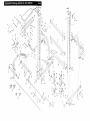
Note:A PartList/Exploded
Drawingis attachedin thecenterof thismanual.Removethe PartList/Exploded
Drawingbeforebeginning
assembly.
4...
v
•
beginning this or any exercise program, consult your physician. This iS especially
e of 35or persons with pre-existing health problems. Read all
• SEARS assumes no responsibility for personal injury or property damage
lined by or through the use of this product,
3
man .EQr set
,ecmg
mevercame
IMAGE"
e..e.
at 1-800-736-6879,
MOnday through Saturday, 7 a.m.
welgl_tb_nch. The IMAGE" 3.8 is aemgned to help you
develop every major muscle group of the body.
Whether your goal is a shapely figure, dramatic muscle size and strength, or a healthier cardiovascular
system, the'IMAGE" 3.8 will herp you achieve the specific results you want.
until 7 p.m. Central Time (excluding holidays). To help
us assist you, please note the product model number
and serial number before calling. The model number is
831.159700. The serial number can be found on a
decal attached to the IMAGE" 3.8, see the front cover
of this manual).
For your benefit, read this manual carefully before
using the IMAGE" 3.8 weight bench. If you have
additional questions, please call our toll-free HELPLINE
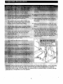
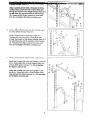
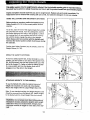
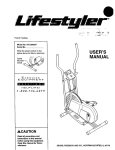
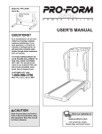
Before reading further, please review the drawing
below and familiarize yourself with the parts that are
labeled.
Note: The terms "right side" and "left side"
are determined relative to a person sitting
on the bench. They do not refer to right
and left on the drawings in this manual,
Right Side
Weight Guide
Left Side
Upright
BarbellWeight Glider
Storage
Tube
Safety
Backrest
Seat
Bracket
4
•
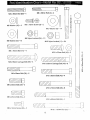
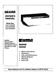
M6 x 38mm Bolt (60)--1
M6 Washer
(30)--5
F_
t_\\\\\\\\\
t_\\\\\\\\\\\\\\\\_
T
M6 x 55mm Bolt (4)--4
M6 x 16mm Screw (3)--2
MIO Washer
(6)--14
J
J
J
J
J
J
J
J
J
M8 Nylon Locknut
M8 Washer
(52)--10
(54)--13
MIO Nylon Locknut
(11)--24
_\\\\\\\\\
M8 x 70mm Bolt (41)_
M8 x 65mm Carriage
Bolt (59)--4
MIO x 25mm Bolt (43)--2
oJ
0,\\\\\\\\\\\\\\\\
•
t'n
MIO x 65ram Carriage
Bolt (40)
I
o
E
E
8
o
oO
_\\\\\\\\\1
X
0
M8 x 60mm Bolt (39)--2
MIO x 65mm Bolt (42)4
_\\\\\\\!
M8 x 30mm Bolt (38)--2
MIO x 70mm Bolt (46)--8
M8 x 25ram Bolt (53)--2
MIO x 80mm
Bolt (56)--1
M8 x 16mm Screw (50)--2
MIO x 115mm Bolt (55)-. °
5
1
• r
_"
u
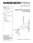
Before beginning assembly, carefully read the
following Information and Instructions:
IDENTIFICATION
CHART on page 5.
• As you assemble the weight bench, make sure all
parts are oriented as shown in the drawings.
In addition to the included allen wren_ch
,
assembly requires the following tools (not
included):
• Two (2) adjustable
wrenches
• One (1) rubber mallet
• Assembly requires two people.
• One (1) standard screwdriver
• Place all parts in a cleared area and remove the
packing materials. Do not dispose of the packing
matedals until assembly is completed.
• One (1) phillips screwdriver
• Lubricant, such as grease or petroleum jelly,
and soapy water.
• Tighten all parts as you assemble them, unless
instructed to do otherwise.
Assembly will be more convenient if you have the
following tools: A socket set, a set of open-end or
closed-end wrenches or a set of ratchet wrenches.
• For help identifying small parts, use the PART
1.
Before beginning, make sure that you understand
the information in the box above. Note: Some
parts described in the assembly steps may be
pre-assembled.
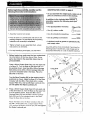
Press a 50mm Square Outer Cap (17) onto each end
of a Base (7). Turn the Base so the large hole is in
the.position shown. Insert two M8 x 65mm Carriage
Bolts (59) and two M10 x 65mm Carriage Bolts (40)
up into the indicated holes in the Base. Place the
Base flat on the floor,
Turn the Base Crossbar (20) so the waming decal is
positioned as shown. Attach the Base (7) to the Base
Crossbar with two M8 x 70mm Bolts (41); a Large
Support Plate (12), and two M8 Nylon Locknuts (54).
Do not tighten the Nylon Locknuts yet.
Decal
/
Press a 50mm Square Outer Cap (17) onto each end
of the other Base (7). Turn the Base so the large hole
is in the position shown. Insert two M8 x 65mm
Carriage Bolts (59) and two MIO x 65mm Carriage
Bolts (40) up into the indicated holes in the Base.
Place the Base flat on the floor.
Attach the Base (7) to the Base Crossbar (20) with
two M8 x 70mm Bolts (41), a Large Support Plate
(12), and two M8 Nylon Locknuts (54). Do not tighten
the Nylon Locknuts yet.
6
17
12
Large Hole
7
17
41
59
4O
2
41
2.
54
17
12
54
Large Hole
17
59
54
2O
4O
":
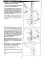
M10 x 65mm Bolts (42), four M10 Washers (6), and
two M10 Nylon Locknuts (11). Do not tighten the
Nylon Locknuts yet.
Slide the Upright (1) and the Brace (2) onto the M10
x 65mm Carriage Bolts (40) and the M8 x 65mm
Carriage Bolts (59) in the left Base (7). Attach the
Upright with two M10 Nylon Locknuts (11). Attach the
Brace with two M8 Washers (52) and two M8 Nylon
Locknuts (54). Do not tighten the Nylon Locknuts
yet.
59
4O
4,
Slide the remaining Brace (2) onto the bracket on the
other Upright (1). Attach the Brace to the Upright with
two M10 x 65mm Bolts (42), four MIO Washers {6),
and two MIO Nylon Locknuts (11). Do not tighten
the Nylon Loeknuts yet.
Slide the Upright (1) and the Brace (2) onto the M10
x 65mm Carriage Bolts (40) and the M8 x 65mm
Carriage Bolts (59) in the right Base (7). Attach the
Upright with two M10 Nylon Locknuts (11)o Attach the
Brace with two M8 Washers (52) and two M8 Nylon
Locknuts (54). Do not tighten the Nylon Locknuts
yet.
4
-all
42
Bracket
54
J
;40
7
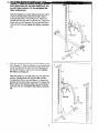
While a second person holds a Crossbar (8)in Me
position shown, Insert two M10 x 70mm Bolts (46)
through the bracket on the Weight Storage Tube (21),
the left Brace (2), and the bracket on the Crossbar
(8). Thread an M 10 Nylon Locknut (11 ) onto each
Bolt. Do not tighten the Nylon Locknuts yet.
46
6,
Press a 25mm Round Inner Cap (51) into the end of
the other Weight Storage Tube (21).
51
51
46
While a second person continues to hold the
Crossbar (8), insert two MIO x 70ram Bolts (46)
through the bracket on the Weight Storage Tube (21),
the right Brace (2), and the bracket on the Crossbar
(8). Thread an M10 Nylon Locknut (11) onto each
Bolt. Do not tighten the Nylon Locknuts yet.
8
7.
Have a second person hold the other Crossbar (8).
Attach the Crossbar (8) to the left Upright (1) with two
M10 x 70mm Bolts (46), a Small Support Plate (16),
and two M10 Nylon Lecknuts (11). Do not tighten
the Nylon Locknuts yet.
7
46
16
8
Attach the Crossbar (8) to the right Upright (1) with
two M1O x 7Omm Bolts (46), a Small Support Plate
(.16), and two M10 Nylon Locknuts (11). Do not tighten the Nylon Locknuts yet.
11
\
16
1
-.a ,1,8
46
_
.
.
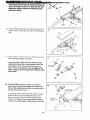
Insert the Barbell (35) through the locking Bar (34)
until the Barbell Is centered in the Locking Bar.
9.
Identify the Left Weight Glider (32) by looking at the
position of the round tube.
9
Press a 38ram Bushing (29) into each end of the
round tube on the Left Weight Glider (32).
32
29
Slide the Left Weight Glider (32) onto the left end of
the Barbell (35). Secure the Weight Glider to the
Barbell with a hand-tightened M8 x 16mm Screw (50).
Look at the drawing on page 4 to make sure that
you have correctly identified the left end. The Left
Weight Glider must be turned as shown in the
drawing.
10. Identify the Right Weight Glider (31) by looking at the
position of the round tube.
35
5O
29
Round tube
10
o
Press a 38mm Bushing (29) into each end of the
welded tube on the Right Weight Glider (31).
Slide the Right Weight Glider (31) onto the right end
of the Barbell (35). Secure the Weight Glider to the
Barbell with a hand-tightened M8 x 16mm Screw (50).
Make sure that the Weight Glider is turned as
shown in the drawing.
11. Note: If you are not planning to use Olympic weights
with the weight bench, you do not need to perform
this step. Keep the two Weight Adapters (33) in a
safe place in case you need them in the future.
Slide a Weight Adapter (33) onto one end of the
Barbell (35). Using the allen wrench, secure the
Weight Adapter with an MIO x 25mm Bolt (43) and a
Large Washer (44). Note: The Large Washer must
fit into the indentation
in the 50ram Bushing (47)
in the Weight Adapter.
Attach the other Weight Adapter (33) to the other end
of the Barbell (35) in the same manner•
9
11
35
33
47
44 /
/"
43
Left Safety Spotteris positioned as shown,thehandle.
willpoint toward the center of the bench.
Place the Left Safety Spotter (24) on the left Base (7)
so it is centered over the indicated hole.
Have a second person hold the Locking Bar (34) so
that the Left Weight Glider (32) rests on top of the
Left Safety Spotter (24)..Insert a Weight Guide (18)
into the Left Weight Glider, the Left Safety Spotter,
and the hole in the Base (7). Note: It may be necessery to tilt the Weight Guide away from the
Upright
(1) as you insert it.
Attach the Weight Guide (18) to the Base (7) with an
M8 x 60ram Bolt (39), two M8 Washers (52), and an
M8 Nylon Locknut (54). Do not tighten the Nylon
Locknut yet.
34
Hole
52
13. Place the Right Safety Spotter (23) on the right Base
(7) and center it over the indicated hole. Note: The
handle must point toward the center of the bench.
39
13
Have a second person hold the Locking Ba_ (34) so
that the Right Weight Glider (31) rests on top of the
Right Safety Spotter (23). Insert a Weight Guide (18)
into the Right WeightGlider, the Right Safety Spotter,
and the hole in the Base (7). Note: It may be necessary to tilt the Weight Guide away from the
Upright (1) as you insert it.
39
23\
Attach the Weight Guide (18) to the Base (7) with an
M8 x 60mm Bolt (39), two M8 Washers (52), and an
M8 Nylon Locknut (54). Do not t!ghten the Nylon
Locknut yet.
14. Attach the upper end of one of the Weight Guides
(18) to the bracket on the Upright (1) with an M8 x
30mrfi Belt (38) and an MB Washer (52).
Attach the other Weight Guide (18) to the other
Upright (1) in the same manner.
Tighten the M8 x 16ram Screws (50) used in steps
9to 10.
Tighten all of the Nylon Locknuts used in steps 1
to 14.
10
18---
1
_"
A11
Attach the Small Stabilizer (25) to the Bench Frame
•..
(5) with two M10 x 65mm Cardage Bolts (40) and two
M10 Nylon Locknuts (11). Note: There is an indentation around the holes on one side of the Small
"_A
_
i//_r
I 11- -
5
"
"
#'-"_.']'!I
_'1 iI
'4f "--_F_._,<4_>
Stabilizer. This side must be facing the floor.
_._'_'_"_
25
40J_J
16. Press a 50mm x 70mm Outer Cap (10) onto each
end of the Large Stabilizer (26).
16
Turn the Large Stabilizer (26) so the warning decal is
in the position shown. Attach the Large Stabilizer to
the Bench Frame (5) with two M10 x 65ram Carriage
Bolts (40) and two M10 Nylon Locknuts (11). Note:
There is an indentation around the holes on one
side of the Large Stabilizer. This side must be facing the floor.
Decal
10
40
17. Press two 20mm x 40ram Inner Caps (28) into each
Backrest Tube (27). Press four 20mm x 40ram Inner
Caps into the Backrest Adjustment Bracket (36).
Lubricate an MIO x 180mm Bolt (22). Attach the
Backrest Tubes (27) to the welded tube on the
Backrest Adjustment Bracket (36) with the Bolt, two
M10 Washers (6), and an M10 Nylon Locknut (11).
Make sure that the Backrest Tubes are turned as
shown. The indicated holes are not centered in
the Backrest Tubes but are closer to one side.
Turn the Backrest Tubes so the holes are closer
to the floor. Do not overtighten the Nylon Locknut;
the Backrest Tubes must pivot easily.
17
Lubricate
22_
\
27
28
6
28
Wel
Tube
18. Attach the Backrest Adjustment Bracket (36) to the
bracket on the Bench Frame (5) in the following way:
Lubricate an M10 x 115mm Bolt (55). Slide an M10
Washer (6) onto the Bolt and insert the Bolt through
the indicated tube of the Backrest Adjustment Bracket
(36).
18
55
36
27
Lubricate
36
Hold the Backrest Adjustment Bracket (36) over the
bracket on the Bench Frame (5). Insert the Bolt
through one side o1 the bracket. Slide the 15mm x
10.2mm x 60mm Spacer (57) onto the Bolt. Next,
insert the Bolt through the other side of the bracket
and the other tube of the Backrest Adjustment
Bracket. Secure the Bolt with an M10 Washer (6) and
an M10 Nylon Locknut (11). Do not overtighten the
Nylon Locknut.
11
27
and an M10 Nylon Locknut (11). Note: Do not overtighten the Nylon Locknut; the Backrest Tubes
must pivot easily.
Tube
20. Attach theBackrest (15) to the Backrest Tubes (27)
with tour M6 x 55ram Bolts (4) and four M8 Washers
(3O).
6
2O
15
:
21. Press a 25ram x 5Ornm inner Cap (58) into the open
end of the Seat Support Tube (37).
21
27
9
45
Lubricate an M8 x 80mm Bolt (9). Attach the Seat
Adjustment Bracket (45) to the indicated side of the
Seat Support Tube (37) with the Bolt and an M8
Nylon Locknut (54). Note: Do not overtighten the
Nylon Leeknut; the Seat Adjustment Bracket must
pivot easily.
37
Lubricate
54
58
22. Place the S_a_tSupport Tube (37) on the Bench
Frame (5) so that the Seat Adjustrrfent Bracket (45)
fits over the welded pin (not visible in tbe drawing) on
the side of the Bench Frame.
Lubricate an M10 x 80mm Bolt (56). Attach the Seat
Support Tube (37) to the indicated bracket on the
Bench Frame (5) with the Belt and an M10 Nylon
Locknut (11)+ Note: Do not overtighten the Nylon
Locknut; the Seat Support Tube must pivot easily•
22
37_
45
Lubricate
56
Welded
Pin
-@
\
11
12
": • -
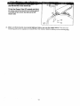
(37) with two M6 x 16mm Screws (3).
Tilt the Seat Support Tube (37) upwards and attach
the narrow end of the Seat (14) to the Seat Support
Tube with an M6 x 38ram Bolt (60) and an M6
Washer (30).
37
24. Make sure that all parts are properly tightened before you use the weight bench. The use of all
remaining parts will be explained in ADJUSTING THE WEIGHT BENCH starting on the following page.
. °
13
Th_ _lori
explains how the weight bench Is adjusted. See the Included exercise guide for important Information abo_ how to perform a variety of exemlses and how to get the greatest benefit from your exercise program.
Inspect and tighten all parts each time you use the weight bench. Replace any wom parts immediately. The
weight bench can be cleaned with a damp cloth and a mild, non-abrasive detergent. Do not use solvents.
USING THE LOCKING BAR AND SAFETY SPOTTERS
Before starting an exercise, position the barbell and the
Safety Spotters (23, 24) in the correct position for that
exercise.
To do this, stand in front of the cage and grip the Locking
Bar (34) with both hands. Turn the Locking Bar until the
two hooks disengage the slots in the Uprights (1). Move
the Locking Bar to a new position and turn the Locking
Bar until the hooks engage the slots in the Uprights.
Note: Always start an exercise with the barbell positioned at the lowest point to which it will move during
the exercise,
Position both Safety Spotters (23, 24) directly under the
Weight Gliders (31, 32).
USING THE SAFETY SPOTTERS
To move a Safety Spotter (23, 24 [not shown]) to a new
position, grip the handle on one side of the Spotter Hook
(61, 62 [not shown]) and pull the Spotter Hook out of the
slot in the Upright (1). Raise or lower the Safety Spotter
to a new position and turn the Spotter Hook until it
engages one of the slots in the Upright.
A'n'ACHING WEIGHTS TO THE BARBELL
To use the Barbell (35), slide the desired amount of
weight (not inoluded) onto each end of the Barbell.
Secure the weights with the Large Weight Clips (13).
Note: To use standard weights, the Weight Adapters (33)
should be removed from the Barbell (35). Attach weights
to the Barbell with the Small Weight Clips (not shown).
35
13
WARNING; Do not place m_re than 260 pounds on
the:barbelL Always secure the weights with weight
clips when they are on the barbell. Always place
the same amount of weight on each side of the barbell.
14
./
Toraise
the Backrest (15), grip the end of the Backrest
with one hand and pull it upwanJ. The Backrest
Adjustment Frame (36) will automatically lock into one of
the tabs on the bracket on the Bench Frame (5).
To lower the Backrest (15), grip the end of the Backrest
with one hand and pull it slightly upwards. Grip the handle
(not shown) on the right side of the Backrest Adjustment
Frame (36) with your other hand and pull the Backrest
Adjustment Frame free of the tabs on the bracket on the
Bench Frame (5). Lower the Backrest to the desired position and lock the Backrest Adjustment Frame into the
desired tab on the bracket on the Bench Frame.
ADJUSTING
THE
Handle
½
Adjustment
Bracket
SEAT
To raise the Seat (14), litt the narrow end of the Seat until
the appropriate tab on the Seat Adjustment Bracket (45)
engages the welded pin (not shown) on the right side of
the Bench Frame (5).
To lower the Seat (14), use the handle on the Seat
Adjustment Bracket (45) to disengage the Seat
Adjustment Bracket from the pin. Lower the Seat to the
desired position and engage the appropriate tab on the
Seat Adjustment Bracket to the pin.
Handle
Pin_
l / /"
I .
15
45
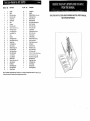
KeyNo.
Qty.
Description
1
2
3
4
5
6
7
8
9
10
11
• 12
13
14
15
16
17
18
19
20
21
22
23
24
25
26
27
28
29
30
2
2
2
4
1
14
2
2
1
2"
24
2
2
1
1
2
6
2
2
1
2
2
1
1
1
1
2
8
4
5
Upright
Brace
M6 x 16mm Screw
M6 x 55mm Bolt
Bench Frame
M10 Washer
Base
Crossbar
M8 x 80mm Bolt
50mm x 70mm Oute_ Cap
M10 Nylon Locknut
Large Support Plate
Large Weight Clip
Seat
Backrest
Small Support Plate
50ram Square Outer Cap
Weight Guide
Small Weight Clip
Base Crossbar
Weight Storage Tube
M10 x 180ram Bolt
Right Safety Spotter
Left Safety Spotter
Small Stabilizer
Large Stabilizer
Backrest Tube
20mm x40mm Inner Cap
38mm Bushing
M6 Washer
31
32
33
1
1
2
Right Weight Glider
Left Weight Glider
Weight Adapter
Key No.
Qty.
34
35
36
37
38
39
40
41
42
43
44
45
46
47
48
49
50
51
52
53
54
55
56
57
58
59
60
61
62
#
1
1
1
1
2
2
8
4
4
2
2
1
8
2
2
8
2
2
10
2
13
1
1
1
1
4
1
1
1
1
#
#
1
1
Description
Locking Bar
Barbell
Backrest Adjustment Bracket
Seat Support Tube
M8 x 30mm Bolt
M8 x 60ram Bolt
M10 x 65mm Carriage Bolt
M8 x 70mm Bolt
M10 x 65ram Bolt
M10 x 25mm Bolt
Large Washer
Seat Adjustment Bracket
M10 x 70mm Bolt
50mm Bushing
25ram Bushing
45mm x 45ram Bushing
M8 x 16ram Screw
25mm Round Inner Cap
M8 Washer
M8 x 25ram Bolt
M8 Nylon Locknut
MIO x 115mm Bolt
M10 x 80ram Bolt
15mm x 10.2 mm x 60mm Spacer
25mm x 50mm Inner Cap
M8 x 65ram Carriage Bolt
M6 x 38ram Bolt
Right Spotter Hook
Left Spotter Hook
User's Manual
Exercise Guide
6mm AllenWrench
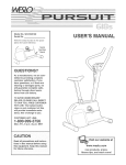
Note: =#" indicates a non-illustrated part. Specifications are subject to change without notice. See the back cover
of the user's manual for information about ordering replacement parts.
SAVE
THIS
PART
LIST/EXPLODED DRAWING AND THE USER'S MANUAL
FOR FUTURE REFERENCE
16
28
8
11
11
2
30
/
21
6
11
42
46
28
57
/
12
11
52
54
11
1(3
20
11
18
17
o
o
i
11
49
17
:
4o'
7
17
o
49
50
32
10
o
o
\
17
48
50
52
40
17
• 29
54
31.,_
29
"49
49
a
;
I
34
29
35
13
49
2
""
49 _62
47
33
49
53
I
49
53
54
52
41
19
59
33
44
48
47
J
43
17
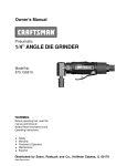
51
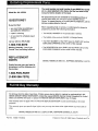
The model number and serial number of your IMAGE 3.8 are listed on a decal attached to the frame. See the front cover of this
manual to find the location of the decal.
Model No. 831.159700
All replacement parts are available for immediate purchase or
special order when you visit your nearest SEARS Service
Center. To request service or to order pads by telephone, call the
toll-free numbers listed at the left.
QUESTIONS?
If you find that:
• you need help assembling
operating the IMAGE 3.8
When requesting help or service, or ordering pads, please be
prepared to provide the following information:
or
• a part is missing
• The MODEL NUMBER
• or you need to schedule repair
service
• The NAME of the product (IMAGE 3.8 Weight Bench)
call our toll-free HELPLINE
of the product (831.159700)
• The PART NUMBER of the PART (see the PART LIST and the
EXPLODED DRAWING at the center of this manual)
1-800-736-6879
Monday-Saturday, 7 am-7 pm
Central Time (excluding holidays)
• The DESCRIPTION of the PART (see the PART LIST and the
EXPLODED DRAWING at the center of this manual).
REPLACEMENT
PARTS
SEARS, ROEBUCK
AND CO., HOFFMAN
ESTATES, IL 60179
If parts become worn and need to
be replaced, call the following tollfree number
1-800-FON-PART
(1-800-366-7278)
For 90 days from the date of purchase, if failure occurs due to defect in material or workmanship in this
SEARS WEIGHT BENCH EXERCISER, contact the nearest SEARS Service Center throughout the United
States and SEARS will repair or replace the WEIGHT BENCH EXERCISER, free of charge.
This warranty does not apply when the WEIGHT BENCH EXERCISER is used commercially or for rental
purposes.
This warranty gives you specific legal rights, and you may also have other rights which vary from state to
state.
SEARS,
Part No. 160861 R1099A
ROEBUCK
AND CO., DEPT.
8t7WA,
HOFFMAN
ESTATES,
IL 60179
Printed in China © 1999 Sears, Roebuck and Co.