1
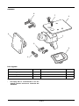
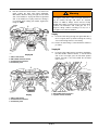
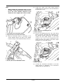
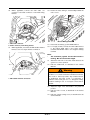
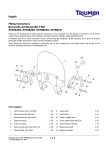
English
Fitting Instructions:
Trophy and Trophy SE
A9828009 and A9828011
Thank you for choosing this Triumph genuine accessory kit. This accessory kit is the product of Triumph's use of proven
engineering, exhaustive testing, and continuous striving for superior reliability, safety and performance.
Completely read all of these instructions before commencing the installation of the accessory kit in order to become
thoroughly familiar with the kit’s features and the installation process.
These instructions should be considered a permanent part of your accessory kit, and should remain with it even if your
accessory-equipped motorcycle is subsequently sold.
A9828009
Parts Supplied:
1.
Mounting arm
1 off
4.
Screw, M5 x 12 mm
2 off
2.
Mounting plate, GPS cradle
1 off
5.
Screw, M5 x 14 mm
2 off
3.
Screw, M5 x 20 mm
1 off
6.
Finisher
1 off
Publication part number A9900624 issue 3, DC 67960
© Triumph Designs Ltd. 2014
1 of 9
A9828011
Parts Supplied:
1.
Mounting arm
1 off
5.
Screw, M5 x 12 mm
2 off
2.
Mounting plate, GPS cradle
1 off
6.
Screw, M5 x 14 mm
2 off
3.
Mounting plate, XM antenna
1 off
7.
Screw, M4 x 12 mm
2 off
4.
Screw, M5 x 20 mm
1 off
8.
Finisher
1 off
Note:
•
For Trophy SE it is recommended to use the
Triumph Genuine Accessories Connector Kit
A9938122.
2 of 9
1.
Disconnect the battery, as described in the Service
Manual.
2.
Remove the windscreen, as described in the Service
Manual.
3.
Remove the mirror covers, as described in the
Service Manual.
4.
Remove the cockpit stowage cover, as described in
the Service Manual.
Warning
This accessory kit is designed for use on Triumph Trophy
and Trophy SE motorcycles only and should not be
fitted to any other Triumph model or to any other
manufacturer’s motorcycle. Fitting this accessory kit to
any other Triumph model or to any other
manufacturer’s motorcycle will affect the performance,
stability and handling of the motorcycle. This may affect
the rider’s ability to control the motorcycle and could
cause an accident.
Note:
•
Warning
Always have Triumph approved parts, accessories and
conversions fitted by a trained technician of an
authorised Triumph dealer. The fitment of parts,
accessories and conversions by a technician who is not
of an authorised Triumph dealer may affect the
handling, stability or other aspects of the motorcycle’s
operation which may result in loss of motorcycle control
and an accident.
When removing the instrument fascia, the two
inner screws adjacent to the upper windscreen
arms, which retain the instrument fascia to the
cockpit front panel, are patch-locked. These
screws must be discarded.
Warning
Always ensure that the newly installed wiring does not
chafe against other parts of the motorcycle such that it
may be rubbed through and cause an electrical
problem. In addition, always ensure that the newly
installed wiring will not restrict steering movement. Both
conditions are hazardous and could give rise to a
dangerous riding condition resulting in a fire, loss of
motorcycle control and an accident.
Warning
4
1. Screw, patch-locked (left hand shown)
2. Upper windscreen arm (left hand shown)
5.
Remove the instrument fascia, as described in the
Service Manual.
6.
Collect the GPS mount components from the kit.
Throughout this operation, ensure that the motorcycle is
stabilised and adequately supported to prevent risk of
injury from the motorcycle falling.
Warning
A torque wrench of known accurate calibration must be
used when fitting this accessory kit. Failure to tighten
any of the fasteners to the correct torque specification
may affect motorcycle performance, handling and
stability. This may result in loss of motorcycle control and
an accident.
3 of 9
7.
Assemble the components as shown below. Tighten
the M5 x 20 mm screw to 4 Nm. For A9828011
only, tighten the M4 x 12 mm screws to 3 Nm.
Trophy SE A9828011 only
8.
Disconnect the XM satellite antenna connection,
located in the area behind the left hand mirror cover.
A9828009
1. XM satellite antenna connector
1. Mounting arm
2. Mounting plate, GPS cradle
3. Screw M5 x 20 mm
9.
Remove the XM satellite antenna assembly from the
motorcycle. Retain the antenna assembly and fixings
for use if the motorcycle is returned to original
condition.
10. Remove the four M3 screws from the XM satellite
antenna assembly. Retain the screws for re-use.
11.
Fit the XM satellite antenna to the new GPS mount
assembly and secure with the original fixings.
Tighten the fixings to 0.5 Nm.
A9828011
1.
2.
3.
4.
5.
Mounting arm
Mounting plate, GPS cradle
Mounting plate, XM
Screw M5 x 20 mm
Screw M4 x 12 mm
1. Mounting plate, XM
2. XM satellite antenna
3. Fixings
12. Attach the GPS cradle, supplied with the GPS unit, to
the GPS mount. Secure with the fixings provided
with the GPS cradle and tighten the fixings to the
torque recommended by the GPS cradle
manufacturer.
4 of 9
13. Fit the finisher provided onto the GPS mount,
routing the GPS cradle harness and XM satellite
antenna harness through the finisher.
All Kits
Note:
•
Before removing the instrument fascia bracket
from the instrument panel, note its orientation
and position to ensure correct reassembly.
16. Remove the instrument fascia bracket from the
instrument panel. Retain the fixings for re-use.
4
1.
2.
3.
4.
Finisher
GPS mount
GPS cradle harness
XM satellite antenna harness
4
Trophy and Trophy SE A9828009
14. Attach the GPS cradle to the GPS mount. Secure
with the fixings provided with the GPS cradle and
tighten the fixings to the torque recommended by
the GPS cradle manufacturer.
1. Instrument panel
2. Instrument fascia bracket
3. Fixings
17.
15. Fit the finisher provided onto the GPS mount,
routing the GPS cradle harness through the finisher.
Fit the GPS mount to the instrument fascia bracket in
the orientation shown. Secure with the two
M5 x 12 mm screws provided. Tighten the screws to
3 Nm.
4
1. Finisher
2. GPS mount
3. GPS cradle harness
4
1. GPS mount
2. Instrument fascia bracket
3. Screw, M5 x 12 mm
5 of 9
18. Refit the instrument fascia bracket to the instrument
panel routing the GPS, and where applicable,
XM satellite antenna wiring through the left hand
side of the bracket for Trophy SE and the right hand
side of the bracket for Trophy. Ensure the wiring is
not trapped when refitting the bracket. Tighten the
fixings to 3 Nm.
Warning
Always ensure that the newly installed wiring does not
chafe against other parts of the motorcycle such that it
may be rubbed through and cause an electrical
problem. In addition, always ensure that the newly
installed wiring will not restrict steering movement. Both
conditions are hazardous and could give rise to a
dangerous riding condition resulting in a fire, loss of
motorcycle control and an accident.
Trophy
19. Route the GPS wiring through the right hand side of
the motorcycle, where possible following the routing
of the main wiring harness to the battery.
20. Ensure the GPS wiring is secured with the cable ties
provided.
Trophy SE
21.
4
1.
2.
3.
4.
Trophy SE
GPS cradle harness
XM satellite antenna harness
Instrument fascia bracket
Instrument panel
Route the GPS cradle harness and where applicable,
the XM satellite antenna harness, to the left hand
side of the motorcycle, past the left hand speaker
bracket through to the area behind the left hand
mirror cover.
Trophy
1. GPS cradle harness
2. XM satellite antenna harness
3. Speaker mount, left hand
1. GPS cradle harness
2. Instrument fascia bracket
3. Instrument panel
6 of 9
Note:
•
When refitting the instrument fascia, use the
two M5 x 14 mm patch-locked screws from the
kit at the inner locations adjacent to the
windscreen arms. Tighten the screws to 3 Nm.
23. Locate the audio and main wiring harness
conditioned power connector in the area behind the
left hand mirror cover.
4
1. Power connector, main wiring harness
2. Audio connector
4
1. Screw, M5 x 14 mm (left hand shown)
2. Upper windscreen arm (left hand shown)
22. Refit the instrument fascia, as described in the
Service Manual. Ensure the GPS mount finisher
locates correctly on the instrument fascia, as shown.
24. Remove the blanking plug from the main wiring
harness connector and using the sub-harness from
the Triumph Genuine Accessories Kit A9938122,
connect the GPS cradle harness to the power
connector. Use of the 12 volt conditioned power
supply will ensure the quality of the audio output
through the on board audio system.
1. Instrument fascia
2. Finisher, GPS mount (A9828009 shown)
4
1. Sub-harness
2. Power connector
25. Connect the sub-harness A9938122 to the GPS
cradle harness as described in the instructions
supplied with the sub-harness kit.
7 of 9
26. Where applicable, connect the GPS audio out
connector to the audio connector on the main wiring
harness.
28. Ensure all excess wiring is secured tidily behind the
mirror cover.
Excess Wiring Position
4
1. GPS audio connector
2. Audio connector, main wiring harness
29. Reconnect the battery, positive RED lead first.
27. Where applicable, reconnect the XM satellite antenna
harness to the motorcycle harness connection.
30. For Trophy models, connect the GPS cradle harness
to the battery, RED lead to the positive battery
terminal and BLACK lead to the negative battery
terminal.
Note:
•
The maximum payload for the GPS mount is
0.39 kg. Do not exceed this weight.
31.
Attach the GPS unit to the GPS cradle and test the
system for correct operation.
32. Refit the windscreen, as described in the Service
Manual.
4
1. XM satellite antenna connection
Warning
Adjust the windscreen to its lowest position and check
that there is no contact between the windscreen and the
GPS mount or GPS components. Any contact between
the windscreen and GPS mount or components is
hazardous and could give rise to a dangerous riding
condition resulting in loss of motorcycle control and an
accident.
33. Adjust the angle of the GPS cradle to the preferred
position.
34. Refit the mirror covers, as described in the Service
Manual.
35. Refit the cockpit stowage cover, as described in the
Service Manual.
8 of 9
Warning
If, after fitting this accessory kit, you have any doubt
about the performance of any aspect of the motorcycle,
contact an authorised Triumph dealer and do not ride
the motorcycle until the authorised dealer has declared
it fit for use. Riding a motorcycle when there is any
doubt as to any aspect of the performance of the
motorcycle may result in loss of control of the
motorcycle leading to an accident.
Warning
Never ride an accessory-equipped motorcycle at speeds
above 80 mph (130 km/h).
The presence of accessories will cause changes in the
stability and handling of the motorcycle. Failure to allow
for changes in motorcycle stability may lead to loss of
control or an accident.
Warning
The motorcycle must not be operated above the legal
road speed limit except in closed course conditions.
Warning
Only operate this Triumph motorcycle at high speed in
closed course, on road competitions or on closed course
racetracks. High speed operation should only be
attempted by riders who have been instructed in the
techniques necessary for high speed riding and are
familiar with the motorcycle’s characteristics in all
conditions.
High speed operation in any other circumstances is
dangerous and will lead to loss of motorcycle control
and an accident.
Remember that the 80 mph (130 km/h) limit will be
reduced by the fitting of non-approved accessories,
incorrect loading, worn tyres, overall motorcycle
condition and poor road or weather conditions.
9 of 9