1
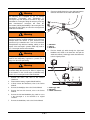
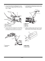
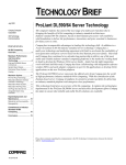
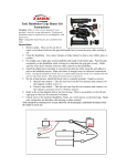
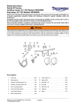
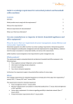
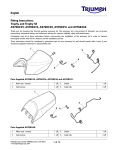
English
Fitting Instructions:
Thunderbird Commander and Thunderbird LT
A9638089
Thank you for choosing this Triumph genuine accessory kit. This accessory kit is the product of Triumph's use of proven
engineering, exhaustive testing, and continuous striving for superior reliability, safety and performance.
Completely read all of these instructions before commencing the installation of the accessory kit in order to become
thoroughly familiar with the kit’s features and the installation process.
These instructions should be considered a permanent part of your accessory kit, and should remain with it even if your
accessory-equipped motorcycle is subsequently sold.
1
4
3
5
6
11
2
10
9
8
7
Parts Supplied:
1.
Heated grip, left hand
1 off
7.
Connector block
2 off
2.
Heated grip, right hand
1 off
8.
Screw, butt head, M4 x 5 mm
2 off
3.
Switch
1 off
9.
Bolt, M6 x 35 mm
2 off
4.
Bracket, switch
1 off
10. Screw, self tapping, M4 x 13 mm
2 off
5.
Spacer
2 off
11.
3 off
6.
Wiring sub-harness
1 off
Publication part number A9900687 issue 1, ADC 12497
© Triumph Designs Ltd. 2013
1 of 7
Cable tie
8.
Warning
Connect a suitable draw wire to the right hand harness
connector and draw out the switch cube harness.
This accessory kit is designed for use on Triumph
Thunderbird Commander and Thunderbird LT
motorcycles only and should not be fitted to any other
manufacturer’s motorcycle. Fitting this accessory kit to any
other manufacturer’s motorcycle will affect the
performance, stability and handling of the motorcycle. This
may affect the rider’s ability to control the motorcycle and
could cause an accident.
1
2
Warning
Always have Triumph approved parts, accessories and
conversions fitted by a trained technician of an authorised
Triumph dealer. The fitment of parts, accessories and
conversions by a technician who is not of an authorised
Triumph dealer may affect the handling, stability or other
aspects of the motorcycle’s operation which may result in
loss of motorcycle control and an accident.
3
1. Handlebar
2. Harness
3. Draw wire
9.
Warning
Throughout this operation, ensure that the motorcycle is
stabilised and adequately supported to prevent risk of
injury from the motorcycle falling.
Feed the heated grip cable through the right hand
handlebar end, fasten to the draw wire and pull the
switch cube harness, heated grip cables and draw wire
to their original position.
1
Warning
A torque wrench of known accurate calibration must be
used when fitting this accessory kit. Failure to tighten any
of the fasteners to the correct torque specification may
result in loss of motorcycle control and an accident.
1.
3
1
Remove the rider’s seat; refer to the Owner’s
Handbook.
2.
Disconnect the battery, negative (black) lead first.
3.
If fitted, remove the windscreen; refer to the Service
Manual.
4.
Remove the headlight; refer to the Service Manual.
5.
Remove the front fork shrouds; refer to the Service
Manual.
6.
Remove the left hand handlebar grip, retain for re-use
if the motorcycle is to be returned to its original
condition.
7.
Remove the handlebars; refer to the Service Manual.
2 of 7
1. Heated grip cable
2. Handlebar
3. Switch cube harness
2
10. Connect a suitable draw wire to the left hand harness
connector and draw out the switch cube harness.
13. Align the switch to the bracket and secure with the two
M4 x 5 mm screws as shown below. Tighten the
screws to 3 Nm.
1
3
2
2
3
1
1. Handlebar
2. Harness
3. Draw wire
11.
Feed the heated grip cable through the left hand
handlebar end, fasten to the draw wire and pull the
switch cube harness, heated grip cables and draw wire
to their original position.
1. Switch
2. Bracket
3. Screws, M4 x 5 mm
14. Refit the handlebars; refer to the Service Manual.
15. Collect the two spacers and two M6 x 35 mm bolts
from the kit.
16. Fit the clamp, spacers, switch bracket and bolts to the
clutch lever assembly as shown below. Do not fully
tighten the bolts at this stage.
1
4
2
5
4
3
3
1
1
4
1.
2.
3.
4.
Handlebar
Harness
Draw wire
Heated grip cable
12. Collect the heated grip switch,
M4 x 5 mm screws from the parts kit.
bracket,
and
3 of 7
1.
2.
3.
4.
5.
Clutch lever assembly
Clamp
Spacer (1 of 2 shown)
Switch bracket
Bolt (1 of 2 shown)
2
17.
Engage the nipples of the throttle cables to the twist
grip. Engage the closing cable first then the opening
cable.
Warning
Move the handlebars to the left and right full lock while
checking that cables and harness do not bind. A cable or
harness that binds will restrict the steering and may cause
loss of control and an accident.
Warning
1
Ensure that the adjuster lock nuts of both cables are
tightened, as a loose lock nut could result in a sticking
throttle.
3
An incorrectly adjusted, sticking or stuck throttle can lead
to loss of motorcycle control and an accident.
19. Rotate both cable adjusters such that there is an equal
amount of adjustment in each direction.
2
cfde_3
1. Opening cable
2. Closing cable
3. Twist grip
1
2
18. Adjust the throttle cable as follows:
1
2
3
4
1
5
2
cfde_1
1. Adjusters
2. Lock nuts
20. Rotate the in-line adjuster on the opening cable to give
2 - 3 mm of play at the twist grip. Tighten the lock nut.
cfhu_1
1.
2.
3.
4.
5.
21.
Opening cable
Closing cable
Closing cable - free play measurement point
Opening cable - free play measurement point
Opening cable in-line adjuster
Warning
Operation of the motorcycle with incorrectly adjusted,
incorrectly routed or damaged throttle cables could
interfere with the operation of the brakes, clutch or the
throttle itself. Any of these conditions could result in loss of
motorcycle control and an accident.
4 of 7
Slide the left hand heated grip fully onto the handlebar.
Ensure that the wiring is located in the cut out in the
handlebar and cannot be trapped.
22. Secure the left hand grip by aligning the two holes in
the grip to the two holes in the handlebar, fit the two
M4 x 13 mm self tapping screws from the kit and
tighten to 4 Nm.
1
24. Feed the heated grip switch harness through the upper
shroud adjacent to the clutch cable and into the area
behind the headlight.
2
3
1
2
1
3
4
1. Heated grip
2. Lower screw location
3. Upper screw location
1.
2.
3.
4.
Switch harness
Cable ties
Upper yoke
Clutch cable
23. Route the switch harness along the line of the left hand
handlebar and into the headstock area, securing it to
the handlebars with two cable ties from the parts kit.
25. Attach the connector blocks from the kit to the left
hand and right hand heated grip wiring as shown
below. Ensure the correct orientation of the terminals.
3
2
2
1
1
4
1. Black terminal
2. Brown terminal
3. Connector block
1. Switch harness
2. Cable ties
5 of 7
26. Connect the heated grip switch connector and both
heated grip connectors to the sub-harness.
28. Remove the blanking plug from the main harness
connector and connect the sub-harness from the kit.
1
2
1. Sub-harness
2. Switch connector
3. Grip connectors
1. Heated grip connector, sub harness
2. Heated grip connector, main harness
Warning
27. The main harness 3-pin connector for the heated grips
is attached to a bracket adjacent to the left hand fork.
When securing electrical cables with cable ties ensure the
cable ties are fully tight. Ensure there is slack in the cables.
Failure to follow this warning may result in damage to the
electrical cables which may lead to loss of motorcycle
control and an accident.
29. Route the heated grip, switch and sub-harness
alongside the existing wiring harness and secure with
the remaining cable tie from the parts kit.
30. Refit the fork shrouds; refer to the Service Manual.
1
31.
Refit the headlight; refer to the Service Manual.
32. If fitted, fit the windscreen; refer to the Service Manual.
2
33. Reconnect the battery, positive (identified with red
tape) lead first.
34. Refit the rider’s seat; refer to the Owner’s Handbook.
ciku
1. Heated grip connector, blanking plug
2. Heated grip connector, main harness
35. Check the operation and beam setting of the front
headlight, adjust if necessary.
6 of 7
Heated Grip Operation
The heated grip switch has three operating modes and will
change colour as described below:
•
OFF - white
•
HOT - red
•
WARM - green or amber.
Warning
After fitting the accessory kit the motorcycle will exhibit
new handling characteristics. Operate the motorcycle in a
safe area free from traffic to gain familiarity with the new
characteristics. Operation of the motorcycle when not
familiar with any new handling characteristics may result in
loss of motorcycle control and an accident.
The system is designed to offer a variable level of heat at the
grips from warm to hot.
For maximum benefit in cold conditions, from the off
position press the switch once for hot (red) initially and then
reduce the heat level by pressing the switch again for warm
(green or amber) when the grips have warmed up.
To turn off the heated grips, press and release the switch
until the colour of the switch is white.
Automatic Shutdown
If the heated grips are switched on and a low battery voltage
situation is detected continuously for five minutes, the
illuminated switch will flash five times. When the illuminated
switch stops flashing the power to the heated grips and LED
warning light will be switched off.
To switch the heated grips on again, press the switch until
the desired heat level is reached, however if the low voltage
condition is still apparent the heated grips will operate for a
further five minutes and then turn off.
Fuses
Thunderbird Commander: Fuse number 2 protects the
heated grips circuit, refer to the label in the fuse box lid for
fuse amperage.
Thunderbird LT: Fuse number 9 protects the heated grips
circuit, refer to the label in the fuse box lid for fuse
amperage.
7 of 7
Warning
If, after fitment of this accessory kit, you have any doubt
about the performance of any aspect of the motorcycle,
contact an authorised Triumph dealer and do not ride the
motorcycle until the authorised dealer has declared it fit
for use. Riding a motorcycle when there is any doubt as to
any aspect of the performance of the motorcycle may
result in loss of control of the motorcycle leading to an
accident.
Warning
The motorcycle must not be operated above the legal
road speed limit except in closed course conditions.
Warning
Only operate this Triumph motorcycle at high speed in
closed course, on-road competition or on closed course
racetracks. High speed operation should only be
attempted by riders who have been instructed in the
techniques necessary for high speed riding and are
familiar with the motorcycle's characteristics in all
conditions.
High speed operation in any other circumstances is
dangerous and will lead to loss of motorcycle control and
an accident.