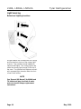
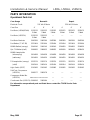
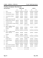
1
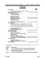
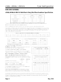
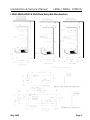
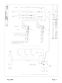
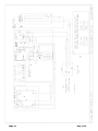
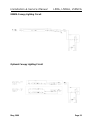
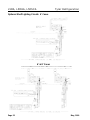
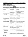
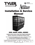
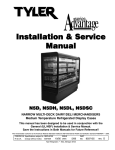
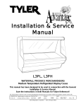
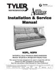
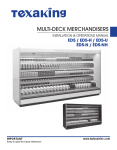
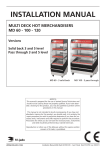
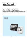
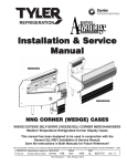
Installation & Service
Manual
L5DA, L5DHA, L5DSCA
NARROW MULTI-DECK DAIRY/DELI MERCHANDISERS
Medium Temperature Refrigerated Display Cases
This manual has been designed to be used in conjunction with the General
Installation & Service Manual.
Save the Instructions in Both Manuals for Future Reference!!
This merchandiser conforms to the Commercial Refrigeration Manufacturers Association Health and Sanitation standard CRS-S1-96.
PRINTED IN Specifications subject to REPLACES
IN U.S.A.
change without notice. EDITION
1/97
ISSUE
DATE
5/99
Tyler Refrigeration Corporation * Niles, Michigan 49120
PART
NO.
9027542
REV.
B
Installation & Service Manual
L5DA, L5DHA, L5DSCA
CONTENTS
Page
Specifications
L5DA/L5DHA/L5DSCA Specification Sheets . . . . . . . . . . . . . . . . . . 4
Pre-Installation Responsibilities . . . . . . . . . . . (See General I&S Manual)
Installation Procedures
Carpentry Procedures . . . . . . . . . . . . . . . . . . . . . . . . . . . . . . . . . 6
Case Pull-Up Locations . . . . . . . . . . . . . . . . . . . . . . . . . . . . . . . . . 6
Electrical Procedures . . . . . . . . . . . . . . . . . . . . . . . . . . . . . . . . . . 6
Plumbing Procedures . . . . . . . . . . . . . . (See General I&S Manual)
Refrigeration Procedures . . . . . . . . . . . (See General I&S Manual)
Defrost Information . . . . . . . . . . . . . . . . . . . . . . . . . . . . . . . . . . . . 6
Defrost Control Chart . . . . . . . . . . . . . . . . . . . . . . . . . . . . . . . . . . . 6
Installation Procedure Check Lists . . . . (See General I&S Manual)
Wiring Diagrams . . . . . . . . . . . . . . . . . . . . . . . . . . . . . . . . . . . . . . . . . . . 6
L5DA/L5DHA Domestic & Export (50Hz) 4’ Case Circuits . . . . . . . . 7
L5DA/L5DHA Domestic & Export (50Hz) 6’ Case Circuits . . . . . . . . 8
L5DA/L5DHA Domestic & Export (50Hz) 8’ Case Circuits . . . . . . . . 9
L5DSCA Domestic & Export (50Hz) 4’ and 6’ Case Circuits . . . . . 10
Canopy Lighting Circuits . . . . . . . . . . . . . . . . . . . . . . . . . . . . . . 11
Optional Shelf Light Circuits . . . . . . . . . . . . . . . . . . . . . . . . . . . 12
Cleaning and Sanitation . . . . . . . . . . . . . . . . . . (See General I&S Manual)
Service Instructions
Preventive Maintenance . . . . . . . . . . . . (See General I&S Manual)
Troubleshooting Self-Contained Units . . . . . . . . . . . . . . . . . . . . 13
Light Servicing
Ballast and Lighting Locations . . . . . . . . . . . . . . . . . . . . . . . . . . . 14
Fan Blade and Motor Replacement . . . . (See General I&S Manual)
Color Band and Bumper Replacement . (See General I&S Manual)
Parts Information
Operational Parts List . . . . . . . . . . . . . . . . . . . . . . . . . . . . . . . . . 15
Cladding and Optional Trim Parts List . . . . . . . . . . . . . . . . . . . . 16
TYLER Warranty . . . . . . . . . . . . . . . . . . . . . . . (See General I&S Manual)
The following Narrow Medium Temperature Dairy and Deli Merchandiser models are covered
in this manual:
MODELS
DESCRIPTION
L5DA
4’, 6’ & 8’ REMOTE MULTI-DECK DAIRY/DELI MERCHANDISER
L5DHA
4’, 6’ & 8’ REMOTE DEEP WELL OR LOW FRONT MULTI-DECK
DAIRY/DELI MERCHANDISER
L5DSCA
4’ & 6’ SELF-CONTAINED MULTI-DECK DAIRY/DELI MERCHANDISER
May, 1999
Page 3
L5DA, L5DHA, L5DSCA
Tyler Refrigeration
SPECIFICATIONS
L5DA/L5DHA/L5DSCA Multi-Deck Dairy/Deli Merchandiser Specification
Page 4
May, 1999
Installation & Service Manual
L5DA, L5DHA, L5DSCA
L5DA/L5DHA/L5DSCA Multi-Deck Dairy/Deli Merchandiser
May, 1999
Page 5
L5DA, L5DHA, L5DSCA
INSTALLATION PROCEDURES
Carpentry Procedures
Case Pull-Up Locations
Tyler Refrigeration
Case Fan Circuit
This circuit is to be supplied by an uninterrupted, protected 120V circuit. The case fan
circuit is not cycled during defrost on any of
these models.
Fluorescent Lamp Circuit
L5DA/L5DHA/L5DSCA case lighting is supplied by 800MA HO horizontal lights. It is
controlled by a light switch in each case. The
standard lighting is 1-row of high output
800MA canopy lights. L5DA/L5DHA/L5DSCA
also offers up to 4 rows of T-8 shelf lights with
remote electronic ballasts.
Self-Contained Circuit
L5DSCA cases are self-contained units.
Information pertaining to self-contained units
should be obtained directly from TYLER
Refrigeration.
Defrost Information
See “General I&S Manual” for operational
descriptions for Off Time defrost control.
Defrost Control Chart
The L5DA, L5DHA and L5DSCA models have
four pull-ups at each end of the case. Pull-ups
A, B, C and D are located as shown and
should be install-ed and tightened starting with
A and finishing with D.
See “General I&S Manual” for line-up
assembly instructions.
Electrical Procedures
Electrical Considerations
CAUTION
Make sure all electrical connections at components and terminal blocks are tight.
NOTE
Since the lower front cladding is shipped
loose, the wiring has immediate access.
Page 6
Defrost
Type
Off Time
Defrost
Defrosts Duration
Per Day
(Min)
4
36
Term.
Temp.
-----
WIRING DIAGRAMS
ELECTRICIAN NOTE - OVERCURRENT
PROTECTION
120V circuits should be protected by 15 or 20 Amp
devices per the requirements noted on the cabinet
nameplate or the National Electrical Code, Canadian
Electrical Code - Part 1, Section 28. 208V defrost
circuits employ No. 12 AWG field wire leads for field
connections. On remote cases intended for end to
end line-ups, bonding for ground may rely upon the
pull-up bolts.
The following wiring diagrams on pages 7
thru 12 will cover the L5DA, L5DHA and
L5DSCA case circuits and the lighting
circuits.
May, 1999
May, 1999
Page 7
Page 8
May, 1999
May, 1999
Page 9
Page 10
May, 1999
Installation & Service Manual
L5DA, L5DHA, L5DSCA
800MA Canopy Lighting Circuit
Optional Canopy Lighting Circuit
May, 1999
Page 11
L5DA, L5DHA, L5DSCA
Tyler Refrigeration
Optional Shelf Lighting Circuits 4’ Cases
6’ & 8’ Cases
Page 12
May, 1999
Installation & Service Manual
L5DA, L5DHA, L5DSCA
SERVICE INSTRUCTIONS
Troubleshooting Self-Contained Units
WARNING
Never work on electrically powered equipment while it is energized! Electrical shock could
cause personal injury and/or death.
TROUBLE
COMMON CAUSE
REMEDY
1. Unit will not run
Blown fuse
Replace fuse.
Low voltage
Check outlet with voltmeter. Voltage
should be 115V or 220V (±10%).
Inoperative motor or
temperature control
Check connections.
Shelves overloaded;
blocked air flow
Make sure items do not block the
air flow.
Thermostat set incorrectly
Check setting.
Pressure control set
incorrectly
Check setting.
Case fans not operating
Check terminal block connections.
Thermostat set incorrectly
Check setting.
Pressure control set
incorrectly
Check setting.
Inadequate air circulation
Relocate cabinet or remove obstruction. Check installation requirements.
Room temperature
too warm
Ventilate room appropriately.
Thermostat set incorrectly
Reset thermostat.
Refrigerant charge low
Have unit serviced by a qualified
service technician.
Loose baffles
Tighten or brace baffles.
Tubing contacting cabinet
or other tubing
Move tubing.
Cabinet not level
Level cabinet.
6. Frost or ice on
evaporator coil
Defrost clock doesn’t work
Check electrical conections. Have
unit serviced by a qualified service
technician.
7. Water dripping from
case drain
Condensate drain clogged
Clear drain.
Dissipator not functioning
Check electrical supply. Check
float assembly.
2. Refrigerated section
is too warm
3. Refrigerated section
too cold
4. Unit runs all the time
5. Noisy operation
May, 1999
Page 13
L5DA, L5DHA, L5DSCA
Tyler Refrigeration
Light Servicing
Ballast and Lighting Locations
All light ballasts are located under the canopy
and mounted on the top of the canopy light
channel. This includes remote ballasts for
optional shelf lights. The canopy light(s) are
under the canopy light channel in the top of
the case. The optional shelf lights are mounted in separate light channels under the front
of each shelf section.
NOTE
See “General I&S Manual” for 800MA and
T-8 ballast and lamp, fan blade & motor
and color band & bumper replacement
instructions.
Page 14
May, 1999
Installation & Service Manual
L5DA, L5DHA, L5DSCA
PARTS INFORMATION
Operational Parts List
Case Usage
Electrical Circuit
Case Size
Domestic
Export
115 Volt 60 Hertz
220 Volt 50 Hertz
4’
6’
8’
4’
6’
8’
Fan Motor (L5DA/L5DHA)
5125532
5 Watt
5125532
5 Watt
5125532
5 Watt
5222975
5 Watt
5222975
5 Watt
5222975
5 Watt
Fan Motor (L5DSCA)
5125532
5 Watt
5125532
5 Watt
----
----
----
----
Fan Motor Brackets
5962269
5962269
5962269
5962269
5962269
5962269
Fan Blades (7” 40° 5B)
5221604
5221604
5221604
5221604
5221604
5221604
800MA Ballast (canopy)
5049140
5049140
5049140
5204859
5204859
5204859
Opt. T-8 Ballast (shelf)
5966635
5966635
5966635
9028439
9028439
9028439
800MA Lampholder
(telescoping)
5614628
5614628
5614628
5614628
5614628
5614628
5614629
5614629
5614629
5614629
5614629
5614629
5232279
5232279
5232279
5232279
5232279
5232279
5092414
5092414
5092414
5092414
5092414
5092414
Light Switch (SPST)
5193982
5193982
5193982
5193982
5193982
5193982
Self-Cont. Compressor
(L5DSCA)
5965977
5965978
----
----
----
----
----
----
----
----
----
----
----
----
(stationary)
T-8 Lampholder (canopy)
(shelf)
Compressor Model No.
(L5DSCA)
REK3-0125-PFV REY3-0175-PFV
Condensate Pan (L5DSCA) 5966016
5965984
For information on operational parts not listed above contact the TYLER Service Parts
Department.
May, 1999
Page 15
L5DA, L5DHA, L5DSCA
Tyler Refrigeration
Cladding and Optional Trim Parts List
Item Description
L5DA/L5DHA
4’
6’
L5DSCA
8’
5183536(3) 5183536(4) 5183536(6)
4’
6’
1
Screw
2
Close-off, Hood
9026366
9026367
9026368
9026366
9026367
3
Canopy Backer, Painted
9026364
9026364
9026364
9026364
9026364
4
Canopy Hood, Painted
9025968
9025969
9025970
9025968
9025969
5
Screw
9025833
9025833
9025833
9025833
9025833
6
Bumper Retainer/Hand Rail
7
Hand Rail Backer, Painted
9025316
9025316
9025316
9025316
9025316
8
Top Band, Painted
9023791
9023796
9023799
9023791
9023796
9
Color Band Backer, Painted 9040223
9040223
9040223
9040223
9040223
10
Bumper
11
Upr. Frt. Cladding, Painted
(L5DA / L5DSCA)
9025462
9025463
9025464
9025462
9025463
(L5DHA)
9026309
9026310
-----
-----
-------------------------
-------------------------
9026308
color by order
color by order
-------------------------
-------------------------
12
Rivet
13
Lwr. Frt. Cladding, Painted
(L5DA / L5DSCA)
9025459
9025460
9025461
9026303
9026304
(L5DHA)
9026306
9026307
-----
-----
14
Screw
15
Kickplate
Kickplate Backer
5104702(4) 5104702(4) 5104702(5)
5183536(3) 5183536(4)
9026305
5183536(6) 5183536(8) 5183536(10)
------------------------9023569
9023569
color by order
9023569
5104702(4) 5104702(4)
5183536(6) 5183536(8)
------------------------9023569
9023569
16
Kickplate Support
9023565(3) 9023565(3) 9023565(4)
9023565(3) 9023565(3)
17
Screw
9029131(6) 9029131(6) 9029131(8)
9029131(6) 9029131(6)
18
Screw
5048626(2) 5048626(2) 5048626(2)
5048626(2) 5048626(2)
19
LH End Close-off, Painted
9022469
9022469
9022469
9022469
9022469
RH End Close-off, Painted
9022471
9022471
9022471
9022471
9022471
20
Bumper Backer
-------------------------
color by order
-------------------------
21
Bumper End Trim
-------------------------
color by order
-------------------------
Page 16
May, 1999
Installation & Service Manual
May, 1999
L5DA, L5DHA, L5DSCA
Page 17