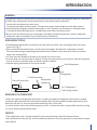
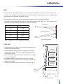
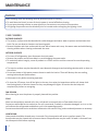
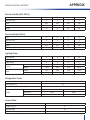
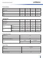
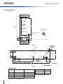
1
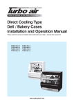
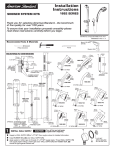
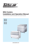
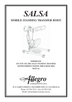
MULTI-DECK MERCHANDISERS
INSTALLATION & OPERATIONS MANUAL
ED5 / ED5-H / ED5-U
ED5-N / ED5-NH
IMPORTANT
Keep in store for future reference!
www.turboairinc.com
REVISION HISTORY
VERSION 1.0
• New manual
2
TABLE OF CONTENTS
GENERAL INFORMATION
Safety Notice
General Information
4
INSTALLATION
Remove Casters
Leveling
Remove Parts
Apply Gasket
Align End Frames
Fasten End Frames
Install Kickplate
5
REFRIGERATION
Refrigerant Piping
Refrigeration Thermostat
Defrost
Plumbing
7
ELECTRICAL
Field Wiring
8
OPERATION
Shelf
Load Limit
9
MAINTENANCE
Case Cleaning
10
APPENDIX
ED5/ED5-H/ED5-U Electrical Data & Case Dimensions
ED5-N/ED5-NH
Electrical Data & Case Dimensions
11
3
GENERAL INFORMATION
SAFETY NOTICE
All warning messages will inform you of the potential hazard; how to reduce the risk of case damage, personal
injury or death; and what may happen if the instructions are not properly followed.
• DANGER – Indicate[s] a hazardous situation which, if not avoided, will result in death or serious injury.
• WARNING – Indicate[s] a hazardous situation which, if not avoided, could result in death or serious injury.
• CAUTION – Indicate[s] a hazardous situation which, if not avoided, could result in minor or moderate injury.
GENERAL INFORMATION
• STORE CONDITIONS
Cases are designed to operate in an air-conditioned store that maintains a 75°F (24°C) store temperature and
55% (max) relative humidity. Case operation will be adversely affected by exposure to excessively high ambient
temperatures and/or humidity.
ANSI/NSF-7 Type I – Display Refrigerator / Freezer Intended for 75°F / 55%RH Ambient Application
• REFRIGERATION SYSTEM OPERATION
Air-cooled condensing units require adequate ventilation for efficient performance. Machine-room temperatures
must be maintained at a minimum of 65°F in winter and a maximum of 95°F in summer. Minimum condensing
temperatures should be no less than 70°F.
• EXTERIOR LOADING
Do not walk on top of merchandisers. It could damage the cases and serious personal injury could occur.
They are not structurally designed to support excessive external loading such as the weight of a person.
Do not place heavy objects on the merchandiser.
• SERIAL NUMBER LOCATION
The serial number is located in left top inside of cabinets.
• SHIPPING DAMAGE
All equipment should be thoroughly examined for shipping damage before and during unloading.
Any claim for loss or damage must be made to the carrier. The carrier will provide any necessary inspection
reports and/or claim forms.
Claims for obvious damage must be noted on either the freight bill or the express receipt and
signed by the carrier’s agent; otherwise, the carrier may refuse the claim. If damage becomes apparent after
the equipment is unpacked, retain all packing materials and submit a written request to the carrier for
inspection within 14 days of receipt of the equipment.
• LOST/MISSING ITEMS
Any claim for missing items must be made to Texaking within 48 hours of receipt of the equipment.
4
INSTALLATION
1) REMOVE CASTERS
• Leave a minimum of 3” between the wall and back of
case. Using a J bar, raise the end of the case , remove
the caster assembly (Fig. 1) and lower the base on to
the shims. Repeat on the other end of the case.
Cotter Pin
Caster
Fig 1. Removing Casters
2) LEVELING
• Once the base is properly placed on the shims, check
the vertical plumb of the case by placing a bubble level
on the rear wall. Add/remove shims as needed. For
the horizontal level, repeat this process after placing the
bubble level on the front. (Fig. 2)
Base
Shims
Fig 2. Leveling
1” End Form Gasket
3) REMOVE PARTS
• Remove shelves, kickplate, pans, wire screens and
return air grilles from the right end.
4) APPLY GASKETS
• Apply the 1 inch gasket around the perimeter of the
case as shown Fig. 3. It must be at the edge. Check to be
sure that there are no gaps between gasket and case.
• A continuous bead of silicone sealant/caulk may be
used in addition to gaskets on mating surfaces but must
not be used in lieu of gaskets.
Fig 3. Gaskets Location
5
INSTALLATION
5) ALIGN END FRAMES
• Move the second case as close to the first as possible by pushing or using lever bar.
• Insert the alignment rod (1/8in diameter) through holes in handrail, thermal barrier and the alignment rod
(15/64 in diameter) through holes in canopy as shown Fig. 4
Insert Alignment Rod
(1/8” diameter)
Canopy
Thermal
Barrier
Hand rail
Insert Alignment Rod
(15/64” diameter)
Insert Alignment Rod
(1/8” diameter)
Fig 4. Alignment Rod Location
6) FASTEN END FRAMES
• Push the cases tightly together, then lightly bolt them
together through the holes that are provided. (Fig. 5)
Tighten all the joining bolts until all margins are equal.
7
1
7) INSTALL KICKPLATE
• The kickplate is shipped inside each case.
• After cases have been leveled and joined,
and all drain piping, electrical and
refrigeration work has been completed
then install the kickplate as shown Fig. 6
3
#1~#6 Bolts Specification
5/16” diameter x 3in bolts
5/16” lock washers
5/16” nuts
4
#7~#8 Bolts Specification
5/16” diameter x 8in bolts
5/16” lock washers
5/16” nuts
Kick plate
Kick plate
Bracket
5
2
6
8
6
Fig 5. Bolting Location
Fig 6. Kickplate Installation
REFRIGERATION
WARNING
• Refrigeration lines are under pressure and should be depressurized before attempting to make any connections.
• Always wear safety glasses and protective gloves when working with refrigerants.
Contact with refrigerant may cause injury.
Disconnect pipes with extreme caution. All pipes may contain liquid refrigerant under high pressure.
• Avoid breathing refrigerant and lubrication vapor or mist. Exposure may irritate eyes, nose and throat.
If accidental system discharge occurs, ventilate work area before resuming service.
• Be sure that any room where you are working is thoroughly ventilated, especially if a leak is suspected.
Refrigerant vapor is hazardous to your health and can cause death.
REFRIGERANT PIPING
• Standard piping penetration is located at the front-right area of the case, consisting of a pre-cut access
punch-out. (Fig. 7)
• After connections have been made, seal this outlet thoroughly. Seal both the inside and the outside.
We recommend using an expanding polyurethane foam insulation. Cover foam with silicone to prevent
water from entering foam.
• Oil Traps must be installed at the base of all suction line vertical risers.
• Pressure drop can rob the system of capacity. To keep the pressure drop to a minimum, keep the refrigerant
line run as short as possible using a minimum number of elbows.
• Optional piping penetrations are rear and top side.
Rear Refrigeration
Top
Refrigeration
1” Drain Connection
Refrigeration
Electrical Juction Box
Standard
Fig 7. Refrigerant /
Drain Piping Location
REFRIGERATION THERMOSTAT
• When the optional refrigeration thermostat is installed, the optional refrigeration thermostat is located
toward the right end of the case in the electrical junction box. The sensing bulb is located approximately 20 in.
above the coil and 2 ft from the right-hand end (facing front) of the case.
• It can be wired in series with the low-pressure control. It can also be used in a pump down system by wiring
it in series with the liquid solenoid valve.
DEFROST
• The refrigeration cycle is simply turned off by the case controls for a specified amount of time.
• We recommend 4 times per day and 35 minutes fail safe time. There are generally no active defrost components utilized.
7
ELECTRICAL
PLUMBING
• The drain outlet is located in the front-center of the case. (Fig. 7)
• The U trap, furnished with the case, is constructed of schedule 40 PVC pipe. Please ensure that all
connections are water-tight and sealed with the appropriate PVC or ABS cement. Never use drain piping
smaller than the nominal diameter of the pipe.
• The drain lines can be run left or right of the tee with the proper pitch to satisfy local drainage requirements.
• To prevent drain pipes from freezing, do not install drain pipes in contact with uninsulated suction lines.
FIELD WIRING
• Field wiring must be sized for component amperes stamped on the data label in left top inside of case.
• Electrical hookups are made to a junction box located at the bottom-front-right of the case. (Fig. 7)
• All wiring must be in compliance with NEC and local codes.
Use Only Copper Conductors
Fig 8. Wiring Diagram
8
OPERATION
SHELF
• The shelves are individually mounted in 1 in. increments on upright and tabs must be seated firmly into
position in the uprights before loading shelves. The shelves have two position brackets permitting shelves
to be placed in a flat or down-tilt position. (Fig. 9)
• The shelves are designed to support the maximum weight load limits as indicated Table 1.
Exceeding these maximum weight load limits may cause damage to the shelf , case, store products, and
potentially create a hazardous condition for customers and staff.
Flat position
Nominal Shelf Depth
Maximum Load Limit
16 in.
200 lb
18 in.
200 lb
20 in.
250 lb
22 in.
250 lb
24 in.
250 lb
Down tilt position
Fig. 9 Shelf position
Table 1. Weight Limits for Shelving (Flat position)
LOAD LIMIT
Load
Limit
PRODUCT
PRODUCT
LOAD LIMIT
AIR FLOW
• Product should not be placed in cases until merchandiser is at
proper operating temperature.
• Air discharge and return grille must remain open and free of
obstruction at all time to provide proper refrigeration and air
curtain performance.
• Do not stock shelves above load limit decals so that it impinges
on the air flow pattern.
• Overloading will cause malfunction and the loss of proper
temperature levels, particularly when discharge and return air
sections are covered.
• Please keep products within the load limit line shown Fig. 10
PRODUCT
PRODUCT
PRODUCT
Fig. 10 Load Limit
9
MAINTENANCE
WARNING
When cleaning cases the following must be performed prior to cleaning
• To avoid electrical shock, be sure all electric power is turned off before cleaning.
• Do not spray cleaning solution or water directly on fan motors or any electrical connections.
• All lighting components must be dried off prior to insertion and re-energizing the lighting circuit.
CASE CLEANING
EXTERIOR SURFACES
• The exterior surfaces must be cleaned with a mild detergent and warm water to protect and maintain their
finish. Do not use abrasive cleansers and scouring pads.
• Remove kickplate and clean underneath the case with a broom and a mop. Use warm water and a disinfecting
cleaning solution when cleaning underneath the cases.
INTERIOR SURFACES
• First turn off refrigeration, then disconnect electrical power
• Remove the product and all loose debris to avoid clogging the waste outlet.
• To maintain product integrity, move all product to a cooler until the unit has returned to normal operating
temperatures.
• The interior surfaces may be cleaned with most domestic detergents and sanitizing solutions with no harm to
the surface.
• Do not use steam or high water pressure hoses to wash the interior. These will destroy the case sealing,
causing leaks and poor performance.
• Allow cases to dry before resuming operation
• To clean the LED lamps, shut off the lights in the case, then wipe the lamps down with a soft, damp cloth.
Avoid using harsh or abrasive cleaners as they may damage the lights. Be certain that the lamps are
completely dry before re-energizing.
FAN PLENUM
After cleaning be sure the plenum is properly lowered into position.
COILS
Never use sharp objects around coils. Use a soft brush or vacuum brush to Clean debris from coils.
Contact an authorized Service technician if a coil is punctured, Cracked, or otherwise damaged. Ice in or on the
coil indicates the refrigeration and defrost cycle is not operating properly.
Contact an authorized service technician to determine the cause of icing, and to make adjustments as necessary.
HONEYCOMB
Honeycombs should be cleaned every six months. Dirty honeycombs will cases to perform poorly. The
honeycombs may be cleaned with a vacuum cleaner. Soap and water may be used if all water is removed from
the honeycomb cells before replacing.
10
APPENDIX
ED5/ED5-H/DE5-U MODELS
Electrical Data (ED5, ED5-H)
Fans
4’
6’
8’
12’
Fans Per Case
2
2
3
4
Volts
120
120
120
120
Amps
0.6
0.6
0.9
1.2
Watts
40
40
60
80
Fans
4’
6’
8’
12’
Fans Per Case
2
2
4
6
Volts
120
120
120
120
Amps
0.6
0.6
1.2
1.8
Watts
40
40
80
120
LED Lighting
4’
6’
8’
12’
Lights per Row
1
2
2
3
Light Length
4’
3’
4’
4’
Amps
0.24
0.36
0.48
0.72
Watts
28.8
43.2
57.6
86.4
Amps
0.12
0.18
0.24
0.36
Watts
14.4
21.6
28.8
43.2
Electrical Data (ED5-U)
Lighting Data
Canopy
Shelf
Refrigeration Data
Evaporator (°F)
26
Discharge Air (°F)
32
Superheat Set point at Bulb (°F)
6~8
BTU/ft
Parallel
Conventional
ED5, ED5-H
1375
1450
ED5-U
1700
1800
Defrost Data
Type
Timed-Off
Frequency (Hr)
6
Fail Safe (Min)
35
Termination Temp. (°F)
47
11
APPENDIX
ED5/ED5-H/DE5-U MODELS
CASE DIMENSIONS
(unit : inch)
401/8 (1020mm)
22 (559mm)
22 (559mm)
22 (559mm)
811/8
(2060mm)
551/2
(1409mm)
High Front Height
ED5-H : 235/8 inch
22 (559mm)
Coil
Plenum
235/8
(600mm)
195/8
(500mm)
151/8
(383mm)
Ultra Low Front Height
ED5-U : 151/8 inch
H
H
ED5, ED5-H 5 -3/8 (135)
ED5-U 3
-3/8 (85)
321/8 (816mm)
381/8 (970mm)
Standard Front Height
ED5 : 195/8 inch
411/8 (1044mm)
SIDE VIEW
Base
41/8
(105mm)
21/4
(57mm)
67/8
(174mm)
321/8
(816mm)
217/8
(557mm)
Pipe Out Top
(Optional)
381/8
(970mm)
7
57/8
(150mm)
(176mm)
77/8
(200mm)
A
15
(382mm)
L
TOP VIEW
PHYSICAL DATA
12
Case
L
A
4' case
48-1/2" (1221)
24-1/16" (610)
6' case
72-3/16" (1831)
43-15/16" (1157)
8' case
96-3/16" (2442)
56" (1421)
12' case
144-5/16" (3663)
80-1/16" (2031.5)
Drain Pipe (in)
1
Liquid Line (in)
3/8
Suction Line (in)
7/8
411/8
(1044mm)
APPENDIX
ED5-N/ED5-NH MODELS
Electrical Data
Fans
4’
6’
8’
12’
Fans Per Case
2
2
3
4
Volts
120
120
120
120
Amps
0.6
0.6
0.9
1.2
Watts
40
40
60
80
LED Lighting
4’
6’
8’
12’
Lights per Row
1
2
2
3
Light Length
4’
3’
4’
4’
Amps
0.24
0.36
0.48
0.72
Watts
28.8
43.2
57.6
86.4
Amps
0.12
0.18
0.24
0.36
Watts
14.4
21.6
28.8
43.2
Lighting Data
Canopy
Shelf
Refrigeration Data
Evaporator (°F)
26
Discharge Air (°F)
32
Superheat Set point at Bulb (°F)
6~8
BTU/ft
Parallel
Conventional
1460
1560
Defrost Data
Type
Timed-Off
Frequency (Hr)
6
Fail Safe (Min)
35
Termination Temp. (°F)
47
13
APPENDIX
ED5-N/ED5-NH MODELS
CASE DIMENSIONS
(unit : inch)
321/2 (825mm)
16 (406mm)
16 (406mm)
551/2
(1409mm)
18 (457mm)
811/8
(2060mm)
High Front Height
ED5-H : 600mm
18 (457mm)
Standard Front Height
ED5-N : 500mm
53/8
(135mm)
Coil
235/8
(600mm)
195/8
(500mm)
Plenum
241/2 (621mm)
301/2 (775mm)
333/8 (849mm)
SIDE VIEW
Base
41/8
(105mm)
21/4
(57mm)
67/8
(174mm)
141/4
(362mm)
241/2 (621mm)
Pipe Out Top
301/2
(775mm)
7
57/8
(176mm)
(150mm)
77/8
(200mm)
15
A
(382mm)
L
TOP VIEW
PHYSICAL DATA
14
Case
L
A
4' case
48-1/2" (1221)
24-1/16" (610)
6' case
72-3/16" (1831)
43-15/16" (1157)
8' case
96-3/16" (2442)
56" (1421)
12' case
144-5/16" (3663)
80-1/16" (2031.5)
Drain Pipe (in)
1
Liquid Line (in)
3/8
Suction Line (in)
7/8
333/8
(849mm)
WARRANTY
LIMITED WARRANTY
Texaking warrants to the original purchaser of every new cases to be free from defects in material and workmanship under normal use and maintenance for a period of fourteen months from the date of original installation or seventeen months after shipment date from Texaking, whichever occurs first.
Any parts covered by this warrant that are examined and determined by Texaking to have been defective
within fourteen months from the date of original installation or seventeen months after shipment date from
Texaking, whichever occurs first, shall be repaired or replaced as stated below.
Texaking shall be deemed to have fully complied with its obligation under the foregoing warranties by electing
either one of the following procedures, at the sole discretion of Texaking.
1. Furnishing a replacement part, freight collect, in even exchange for the returned part, freight collect.
2. Receiving the defective part, freight collect; repairing it: and returning it, freight collect
WHAT IS NOT COVERED BY THIS WARRANTY
1. To any unit or any part thereof which has been subject to accident, alteration, negligence, misuse or abuse,
operation on improper voltage, or which has not been operated in accordance with the Manufacturer’s recommendation, or if the serial number of the unit has been altered, defaced, or removed.
2. When the unit, or any part thereof, is damaged by fire, flood, or other act of god.
3. To labor cost for replacement of parts, or for freight, shipping expenses, sales tax or upgrading.
4. When the operation is impaired due to improper installation.
5. When installation and startup forms are not properly complete or returned within two weeks after startup.
6. Outside the continental united states.
This plan does not cover consequential damages. Manufacturer shall not be liable under any circumstances for
any consequential damages, including loss of profit, additional labor cost, loss of refrigerant or food products,
or injury to personnel or property caused by defective material or parts or for any delay in its performance
hereunder due to causes beyond its control. The foregoing shall constitute the sole and exclusive remedy of
any purchases and the sole and exclusive liability of manufacturer in connection with this product.
All claims should include: Model number, the serial number of case, proof of purchase, date of installation and
all pertinent information supporting the existence of the alleged defect. Any action or breach of these warranty provisions must be commenced within one year after the cause of action has accused.
MAIL CLAIM TO:
Texaking
1800 s. Great SW Pkwy.,
Grand Prairie, TX 75051
Tel: 214-723-7200 / Fax : 214-723-7215
www.turboairinc.com
15
1800 S. Great SW Pkwy, Grand Prairie, TX 75051
Tel : 214-723-7200 / Fax : 214-723-7215
www.turboairinc.com