1
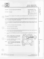
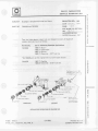
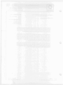
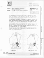
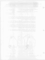
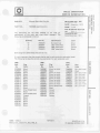
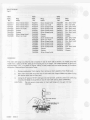
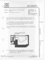
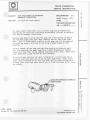
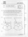
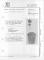
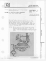
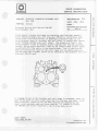
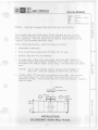
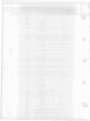
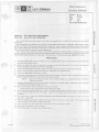
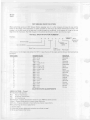
Delco Carburetor
BULLETIN 9D-201
DATE: NOVEMBER, 1971
PAGE 1
FILE I N SERVICE "FIX" SECTION
SERVICE INFORMATION
SUBJECT:
New Screw Kit Released for Monojet Carburetors
PART NUMBER:
7041830 - Screw Kit
/--
A new k i t is released which contains self-locking type screws for use on Monojet carburetors.
The following screws are contained in the kit:
1 - Fast idle cam screw
-
3 - Long air horn screws
3 - Short air horn screws
2 - Throttle body to bowl attaching screws
2 - Air cleaner bracket screws
The special screws in the k i t have self-locking threads and are extremely useful on applications where excessive
engine vibration or rough road operation can cause loose carburetor screws.
CO. WD. 131,132:16,9X.9FR.9FD,9LA
PRINTED I N USA.
@ 1971. GENERAL MOTORS CORP.
DELCO CARBURETOR
SERVICE INFORMATION
D
1
SUBJECT:
P A R T NO.
Quadrajet Secondary Main Well Seal
7041342
0
s?
9
<
-I D
BULLETIN 9D- 202
DATE
November. 1971
PAQE
1
ED
0 =
z0
" 4a
FILE IN 90-200 SECTION
C
0
x
NO.
,
Some cases of fuel leakage at the secondary main well plugs have been reported o n early model
quadra~ets.
I f teakage occurs past the t w o plugs, it will fill the secondary well cavity i n the throttle body with
fuel. The fuel then seeps through the throttle body-to-bowl gasket, and into the carburetor bores
which could result i n rough idle or hard starting.
T o stop this seepage o f fuel, a special Viton* seal i s available for service use only. Use of this seal
avoids the possibility of cracking the bowl when installing some types of plugs available o n the
market.
I
The procedure for installing this seal i s as follows:
-
1.
Remove carburetor from engine.
2.
Disconnect accelerator pump rod.
C
rn
r-
3.
Remove float bowl-to-throttle body attaching screws and t w o long air horn attaching screws
at rear of carburetor and remove throttle body.
V)
n
<
V)
-4
4.
Insert seal. part #7041342, into bottom of secondary well cavity i n throttle body. see figurc
below.
5.
Replace throttle b o d y t o float bowl,
tightening attaching screws and t w o air
horn screws evenly and securely.
6.
Reconnect accelerator pump rod and
install carburetor o n engine.
NOTE: The t w o secondary well plugs should
not be removed when performing
this operation.
'Registered trade-mark E.I. duPont deNemours
PRINTED I N U S A.
8
GENERAL MOTORS CORP.
12
DELCO CARBURETOR
SERVICE I N F O R M A T I O N
SUBJECT:
BULLETIN 9D- 203
Quadrajet - Stripped Fuel Inlet Nut Repair
DATE January,
P A R T NO
7041634 and 7041635
PAGE
1974
1 of 2
FILE I N 9 D - 2 0 0 SECTION
NO,
74-T-1
REPLACES 9D.203
DATED November. 197
Two fuel inlet adapter repair kits are released t o cover all Quadralet
models. Applicat~onsare as follows:
K i t Part No.
Use on Following Ouadrajet Applications
7041634
1966-71 Buick'
1966-71 Oldsmobile
1967-71 Pontiac
1965-71 Chevroiet - 318" fuel line
I
'On 1966 Buick use the original inlet nut with nipple adapter
7041635
1967-71 Cadillac
1966-67 Chevrolet
- 5/16"
fuel line
F U E L I N L E T GASKET
E N D &"EL PI.IIG
FUEL ! N L E T G A S K E T
F U E L l N L E T ADAPTER
F U E L I N L E T ADAPTER
BLOW O F F SPRlNG
NOTE
I N L E T N U T GASKET
ro oullldr dlsmeler
L INLET N U T
0, f u l l , " , e l atlBO1I:
SIDE I N L E T
,-
Enlacqe i n i p l nut
hole ,n "lug r e l a l n r .
,*LET N U T GASKET
INSTALLATION INSTRUCTIONSOJ
(OSS - 0051)
CO:S, 131, 1 3 2 : G - K , FD, WD, X
REVERSE S
(OVER)
s .
PRINTED IN U S A
GENERALMOTORSCORP
INSTALLATION OF FUEL INLET ADAPTER
1.
Remove fuel inlet nut, filter and spring and discard all pans.
2.
Blow out fuel inlet cavity in float bowl making sure it is free of chips and
foreign material..
3.
Apply Loctite Primer "T" to threaded area of bowl and on inlet nut adapter.
Allow Primer "T" to dry on threads.
Note: The use of Loctite adhesive #75 and "T" Primer is t o assure a perma.
nently sealed fitting in the carburetor bowl and no attempt should be made to
remove adapter.
IMPORTANT
Loctite Primer "T" and #75 adhesive sealant is available through pans jobbers
and dealers.
4.
Install one inlet nut gasket on adapter. Coat the threads of adapter which fit into float bowl with Loctite #75. Use extreme caution so Loctite is only on
adapter threads.
Note: On 1966 Model 4MV carburetors the fuel passage end plug retainer
should be used i f needle and seat Modification Kit #7036775 has been installed.
5.
lnstall adapter i n bowl and torque t o 50 ft. Ibs.
6.
Blow out bowl cavity b y blowing air through adapter.
7.
Install new filter spring, filter and inlet nut with gasket.
Note: Care should be taken when installing inlet nut, filter and gasket not t o
move adapter as it takes 5 t o 10 minutes for Loctite t o set up.
8.
Connect fuel line.
9.
Adjust engine t o specified R.P.M.
DELCO CARBURETOR
SERVICE INFORMATION
SUBJECT: SERVICE REPLACEMENT IDLE
LIMITER CAPS
PART NO. All Carburetors
BULLETIN 9D- 204
DATE
November, 1973
PAGE
1
FILE I N 9 D - 2 0 0 SECTION
NO. -
74-1-2
-
- - ..
Replaces 9D-204
dated April, 1972
Special attention is directed t o vehicle manufacturer's recommendations
for idle speed and idle mixture adjunmenrs. Complete effect~venessof the
Exhaust Emission Control system, on vehicles so equipped, depends upon
idle speed and idle mixtures being set t o factory specifications.
The idle mixture is preset ana sealed at the factory with black plastic
limiter caps. The idle mixture caps should not be removed in the field
unless idle mixture adjustment is required after cleaning or major
carburetor repair. I f the idle needle caps are removed the idle mixture
should be reset according t o instructions on the decal in the engine
compartment or as outlined in the service manual.
Red plastic limiter caps were originally used for replacemenr after field
adjustment and were supplied separately and in the repair k i t s . x r % d
limiter *replacement
is no longer required afrer field adjustment, so
they have been discontinued as a replacement part.
(OSS - 0 0 8 5 )
CO:9, 131, 132:G-K, WD, F D , X
PRINTED IN U S A
O GENERAL MOTORS CORP.
DELCO CARBURETOR
SERVICE INFORMATION
SUBJECT:
PART NO.
MONOJET CARBURETOR CHOKE SHAFT
AND LEVER REPLACEMENT
A l l 1968 and l a t e r E b n o j e t c a r b u r e t o r s
"
BuLLlEflN 9D- 205
DATE August,
I
rn
:
<
w
1972
0
r
m
+
PAGE I
FILE I N 9D-200 SECTION
NO,
72-T-1
A l l 1968 Monojet c a r b u r e t o r s have a s l o t i n the f a s t i d l e cam t o
a l l o w f r e e movement of t h e choke rod i n t h e cam. The upper choke
rod l e v e r has a standard h o l e f o r attachment of t h e upper end of
the choke rod t o t h e choke shaft.
I f choke s h a f t replacement i s necessary, i t should be s e r v i c e d w i t h
choke s h a f t and l e v e r assembly, P a r t No. 7034009. The upper choke
rod l e v e r i s s t i l l s e r v i c e d s e p a r a t e l y under P a r t Number 7034056.
-
'I
On 1969 and l a t e r models t h e upper choke l e v e r i s s l o t t e d f o r f r e e
movement of t h e choke rod and t h e f a s t i d l e cam has a standard h o l e .
On these models a choke s h a f t and l e v e r k i t . P a r t No. 7036973, must
be used i f necessary t o r e p l a c e t h e upper choke rod s l o t t e d l e v e r o r
t h e choke s h a f t and c o i l l e v e r assembly.
The new k i t , P a r t Number 7036973, c o n t a i n s a choke s h a f t w i t h t h e
s l o t t e d choke l e v e r spun on one end and a separate choke c o i l rod
l e v e r w i t h an a t t a c h i n g screw.
1968 Models
1969 and l a t e r models
-
(OSS 0519)
CO. WD. 131.132: lO.WX.9FR.9FD.9LA
PRINTED I N U S A .
8
OENERAL MOTORS CORP.
i
,DELCO CARBURETOR
SERVICE I N F O R M A T I O N
,
-
SUBJECT:
Monojet Main Well Plug K i t
PART NO.
7041848 Assortment K i t
B U L L E T I N 9 D - 200
The assortment kit has been released t o the field for
replacement of the main well plug where necessary. The
following are contained in the kit:
DATE January, 1974
PAGE 1 of 2
FILE I N 99-200 SECTION
NO.
74-1-1
Replaces9D~200
Dated November, 1971
Quantity
Part No.
Identification
Color
10
5
5
10
7030470
703047 1
7030472
7030473
No bleed hole
,023" bleed hole
,030" bleed hole
,036" bleed hole
Silver
Silver
Copper
Black
Some plugs have bleed holes and some do nor.
-
--
I t IS very important that the correct plug be used in each particular carburetor model
The follow~nglist gives the correct plug application for each carburetor unlt:
1968
Carb.
No.
7028006
7028007
7028008
7028009
7028010
702801 1
7028012
7028013
7028014
7028015
7028017
7028047
7028057
7028065
7028067
7028082
7028083
7028180
7028181
7028182
Plug
Color
Black
Black
Black
Black
Black
Black
Black
Black
Black
Black
Black
Silver (bleed hole)
Black
Silver (bleed hole)
Copper
Black
Black
Black
Black
Black
(ass - 0051)
CO:9, 131, 132:G-K, FD, WD,
1969
Carb.
No.
7029007
7029008
702901 1
7029012
7029014
Plug
Color
Silver (no hole)
Black
Silver (no hole)
Silver (no hole)
Silver (no hole)
Silver (no hole)
Silver (no hole)
Silver (no hole)
Silver (no hole)
Silver (bleed hole)
Black
Copper
Copper
Copoer
Copper
1970
Carb.
No.
7040007
7040008
704001 1
7040012
7040014
7040017
7040021
7040022
7040025
7040026
(OVER)
X
1
Plug
Color
Silv. (bld. hole)
Black
Silv. (bld. hole)
Silv. (no hole)
Silv. (no hole)
Silv. (no hole)
Silv. (bld. hole)
Silv. (no hole)
Silv. (bld. hole)
Silv. (no hole)
PRINTED IN U S A
@
GENERAL MOTORS COUP.
1
I
BULLETIN 8D-200
Pap2
1971
Carb.
No.
Plug
Color
Silver (bleed hole)
Silver (bleed hole)
Silver (bleed hole)
Silver (no hole)
Copper
Copper
Silver (bleed hole)
Silver (no hole)
1972
Carb.
No.
7042011
7042012
7042014
7042017
7042021
7042022
7042023
7042024
7042025
7042026
7042984
7042987
7042991
7042992
7042993
7042994
7042995
Plug
Color
Silver (bleed hole)
Silver (no hole)
Silver (bleed hole)
Silver (bleed hole)
Silber (bleed hole)
Silver (bleed hole)
Copper
Copper
Silver (bleed hole)
Silver (no hole)
Silver (bleed hole)
Silver (bleed hole)
Silver (bleed hole)
Silver (bleed hole)
Copper
Copper
Silver (bleed hole)
1973
Carb.
No.
7043009
7043012
7043014
7043017
7043021
7043022
7043023
7043024
7043025
7043026
7043312
7043323
7043324
7043326
7043333
7043334
Plug
Color
Silv. (bld. hole)
Silv. (no hole) ,
Silv. (bld. hole)
Silv. (bld. hole)
Silv. (bld. hole)
Silv. (bid. hole)
Copper
Copper
Silv. (bld. hole)
Silv. (no hole)
Silv. (bld. hole)
Copper
Copper
Silv. (bld. hole)
Copper
Copper
Installation:
The main well plug is a press f i t and is located in top of main well as shown. To install usea tool
made from a piece of 5/16" steel gas line tubing cut t o 3" length. The inside diameter of gas line is
approximately 114". I f a piece of regular tubing is used, make sure the inside diameter is the above
dimension. Remove burrs from end of tube.
1.
2.
Removecarburetor from engine; then remove air horn assembly from float bowl.
Start new main well plug into top of main well with fingers. Make sure sides of plug
are vertical with hole in main well.
Using the 3" piece of 5/16" steel gas line and hammer, carefully drive main well plug
inward until bead on plug rests on top of main well casting. SEE DRAWING.
Do not use any type sealer on main well plug as it may get into fuel
CAUTION:
channels.
3.
DELCO CARBURETOR
SERVICE INFORMATION
SUBJECT:
PART NO.
1D
CORRECT l NSTALLATI ON OF FLOAT NEEDLE
PULL CLl P
A l l Quadrajet Carburetors
BULLETIN 9D- 206
DATE
PAGE
August , 1972
1
FILE I N 90-200 SECTION
NO.
72-T-2
r
r
n
P
D
-0
u
<
v,
Z
V)
,
R e p o r t s have been r e c e i v e d o f i n c o r r e c t i n s t a l l a t i o n o f t h e f l o a t
If
n e e d l e p u l l c l i p o n t h e f l o a t arm d u r i n g f i e l d replacement.
t h e c l i p i s n o t i n s t a l l e d as recommended, c a r b u r e t o r f l o o d i n g can
result.
I t i s r e p o r t e d t h a t t h e end o f t h e p u l l c l i p i s b e i n g i n s t a l l e d
t h r o u g h t h e h o l e s i n t h e t o p o f t h e f l o a t arm above t h e n e e d l e .
These a r e l o c a t i n g h o l e s used f o r m a n u f a c t u r e o f t h e f l o a t arm
and a r e & t o b e used f o r t h e p u l l c l i p .
,---
C o r r e c t i n s t a l l a t i o n o f t h e f l o a t n e e d l e p u l l c l i p , i s t o hook t h e
c l i p o v e r t h e edge of t h e f l a t on f l o a t arm f a c i n g t h e f l o a t pontoon,
as shown.
HOOK CLIP OVER EDGE O F
/. F L O A T A R M
,
-
(OSS
Note: The o n l y e x c e p t i o n t o t h i s i s when u s i n g t h e f l o a t n e e d l e
m o d i f i c a t i o n k i t - P a r t Number 7036775. T h i s n e e d l e p u l l
c l i p hooks o v e r t h e o p p o s i t e edge o f f l o a t arm as shown o n
i n s t r u c t i o n sheet i n t h e k i t .
- 0519)
CO. WO. 1 3 1 . 1 3 2 : 1 6 . 9 X . 9 F R . 9 F D . 9 L A
PRINTED I N U S A.
0
GENERAL MOTORS CORP.
DELCO CARBURETOR
SERVICE INFORMATION
SUBJECT:
PART NO.
1
BULLETIN 9D-
PUMP ROD REMOVAL ON ROCHESTER
QUADRAJET CARBURETORS
207
DATE August. 1972
PAGE
1
FILE IN 9D-200 SECTION
~ 1 1970
1
and l a t e r models
NO.
72-T-3
I-
n
%
0
C
It
0
Z
m
The above model c a r b u r e t o r s use a c l i p l e s s pump r o d t o prevent the
p o s s i b i l i t y o f r e t a i n i n g c l i p s belng a c c i d e n t a l l y l e f t o f f o r becoming
l o s t due to improper i n s t a l l a t i o n .
Reports have been received t h a t t h e pump rod i s b e l n g b e n t t o remove
the r o d from upper pump l e v e r when removing t h e a i r horn fran f l o a t
bowl. T h i s i s a bad s a f e t y p r a c t i c e as t h e pump rod w l l l be weakened
and a l s o may cause a b i n d due t o n o t b e i n g a l i g n e d p r o p e r l y a f t e r
bending.
C o r r e c t removal o f t h e pump rod shouid be aone by d r i v i n g the small
r o l l p i n r e t a i n i n g t h e upper pump l e v e r inward (towards a i r cleaner
boss) u n t i l t h e l e v e r can be removed fran boss on a1 r horn. Then remove
upper pump l e v e r , pump rod and a i r horn assenbly.
To i n s t a l l pump rod a f t e r a i r horn i n s t a l l a t i o n , i n s t a l l pump rod t o
t h r o t t l e l e v e r and upper end o f rod t o upper pump l e v e r . Then i n s e r t
upper l e v e r I n t o boss on a i r horn and push r o l l p i n back through h o l e
i n pump l e v e r u n t i l t h e o u t e r end o f p i n I s f l u s h w i t h boss on a i r horn.
See sketch.
I
(OSS
DRIVE PIN INWARD TO REMOVE
PUMP LEVER
- 0519)
PRINTED I N U S A.
CO. W D . 131. 132: 1 6 . 9 X . 9 F R . S F D . 9 L A
0
GENERAL MOTORS CORP.
DELCO CARBURETOR
SERVICE INFORMATION
,-..
SUBJECT:
QUADRAJET A I R VALVE CAM REPLACEMENT
BULLETIN 9D- 209
PART NO.
7035344 A i r V a l v e and S p r i n g K i t
DATE
PAGE
August,
1972
I
FILE I N 9D-200 SECTION
NO.
72-1-2
A cam and s p r i n g k i t i s a v a i l a b l e f o r Q u a d r a j e t a i r v a l v e cam
repair.
The k i t i n c l u d e s t h e cam, s p r i n g , s e t screw, p i n , and
the a i r v a l v e s h a f t seal plug.
T o r e p l a c e cam:
I . Remove a i r v a l v e screws
2. Remove a i r v a l v e s
3. Remcve s e t screw f o r a d j u s t m e n t p i n
4. Remove a d j u s t m e n t p i n
5. Remove wind-up s p r i n g
6. D r i v e o u t a i r v a l v e s h a f t
7. I n s t a l l new cam
8. Reverse above p r o c e d u r e f o r re-assembly
9. I n s t a l l new s h a f t s e a l
10. R e f e r t o s p e c i f i c a t i o n f o r s e t t i n g a i r v a l v e
wind-up.
( ~ u l l e t i n9 ~ - 2 1 0 )
P R I N T E D IN U S A
@
GENEAALMOTORSCORP
DELCO CARBURETOR
SERVICE I N F O R M A T I O N
SUBJECT:
QUADRAJET A t R VALVE CAM RE PLACEMENT
BULLETIN 9DDATE
PART N O .
7035344 A i r V a l v e and S p r i n g K i t
PAGE
209
August,
1972
1
FILE IN 9D-200 SECTION
NO.
72-1-2
A cam and s p r i n g k i t i s a v a i l a b l e f o r Q u a d r a j e t a i r v a l v e cam
r e p a i r . The k i t i n c l u d e s t h e cam, s p r i n g , s e t screw, p i n , and
the a i r v a l v e s h a f t seal plug.
To r e p l a c e cam:
1 . Remove a i r v a l v e screws
2. Remove a i r v a l v e s
3. Remove s e t screw f o r a d j u s t m e n t p i n
4. Remove a d j u s t m e n t p i n
5. Remove wind-up s p r i n g
6. D r i v e o u t a i r v a l v e s h a f t
7. I n s t a l l new cam
8. Reverse above p r o c e d u r e f o r re-assembly
9. I n s t a l l new s h a f t s e a l
10. R e f e r t o s p e c i f i c a t i o n f o r s e t t i n g a i r v a l v e
wind-up.
( B u l l e t i n 9D-210)
(OSS - 0588)
CO:9,131,132:G-K,WD,FD,X
- --
-
~
O
-~
PRINTED IN u s A
GENERAL MOTORS COUP.
- -~
~
~
I
DELCO CARBURETOR
SERVICE INFORMATION
1
D ~ C O
SUBJECT:
PART NO.
A i r Valve Windup Setting Procedure and
Specifications.
BULLETIN 9D- 210
DATE
November, 1 9 7 3
All Quadrajets
PAGE
1 of 2
FILE IN 90-200 SECTION
NO.
72-1-3
Replaces 9 D - 2 1 0
Dated August, 1972
ADJUSTING
. .- .- SCREW
--+
AIR VALVE SPRING ADJUSTMENT
MODEL
YEAR
CARBURETOR NO.
Buick
'66
'67-'69
'70-'72
'73
ALL
A
A
AIR VALVE
WINDUP
(TURNS)
518
112
711 6
711 6
-704x241)-242-243
ll/lfi
7,
""
-,,
'69
'70
'71-'72
'73
ALL
ALL
ALL
71
'74
Ct.:vrolet
'655'66
'67
'68
'69
(0% - 005 1)
C 0 : 9 , 131, 132:G-K, FD, WD,X
7/16
112
5/16
318
318
1 12
5/16
1
718
318
718
13/16
7/16
7043230-231-233
7043232
7044230-233-235-530
7044232-532
7044234
ALL
ALL
7028207-208-21 2-21 9-229
128209-210-211-21:
7029200-21
7029201-2(
(OVER)
- -
-
'-218
PRINTED IN U S A
GENERAL MOTORS CORP.
--
- -
BULLETIN 9D-21
Page 2
MODEL
Chevrolet
Cont'd.
YEAR
'70
'7 1
'72
'73
'74
Oldsrnobile
'6 6
'6 7
'68
'69
'70
'71
'72
'73-'74
Pontiac
'74
'66-'69
'70
'7 1
'72
'73
'7 4
CARBURETOR NO.
7040200-202-203-208-21
3-500-502-503-'508
704051 1-512-513
7040201-204-205-206-207-221-501-504-505
7040506-507-508-521
7041200201 -202-203-204-205-208-209-21
1
7041212-213
7041206
7042200-201 -204-205-209-21
2-21 5-216-21 7
704221 8-219-220
7042202-203-208-210-21
1-902-903;910-911
7042206-207
7043200-201-207
7043215-502-503-508-510-51
1-515
7043212-213-217-224-512-513
7043202-203-21 0-21 1-21 9
7044202-203-206-207-21
3-214-215-216-218-219
7044224-502-503-506-507-51
3-514-51 5-516
7044518-519
7044201-212-217-221-223-225-227-505-512
7044517-520-550
7044208-209-210-21 1
704226-526-527
7026250-256-7036250
7026254-7036254
7026255
70271 56-157
7027036-135-153
7028250
7028251-252-255
7029250
7029251-252-253-254-255
7040251-252-253-255-256-257-258-551-552
7040554-555
7040250-550
7041-252-253-;
7041 250
7042251-252-9
53
7042250-950
7043250-255-256-257
7043251 -252-253-254-2!
7044557-558-559
ALL
7040577
7040262-263-264-267-268-271
-274272;
7040277-562-563-564-567-568-572-575-5;
7040265-266-270-273-565-566-570-573
7041 267-268-270
7041 262-263-264-271
7042262-270-273
7042264
7042267
7042263
7043263
7043265-274
7043262-272
7043264
7044262-267-272-560
7044266-268-21
7044270-273
7044274
-
AIR VALVE
WINDUP
(TURNS1
7116
13116
7116
13116
7116
112
11/16
11116
112
1
314
,
718
7/16
1
314
314
112
518
314
112
112
314
112
314
314
112
314
i 12
314
112
112
314
314
112
318
.
-
7/16
314
1I 2
7116
7116
518
9116
11116
518
9116
318
1
318
112
314
9116
/
2
-
PI
~
'
c
DELCO CARBURETOR
O
SERVICE INFORMATION
I
SUBJECT:
PART NO.
USE OF INCORRECT THROTTLE BODY TO
FLOAT BOWL GASKET
QUADRAJET
-
1970 and L a t e r Q u a d r a j e t C a r b u r e t o r s
BULLETIN 90- 21 1
r
DATE November, 1972
PAGE
1
0
9
FILE IN 90-200 SECTION
NO, 72-1-4
c
r
m
0
-
'A
0
Z
U1
-
F i e l d r e p o r t s , a l o n g w i t h r e t u r n e d samples, i n d i c a t e servicemen somet i m e s a r e s u b s t i t u t i n g t h e wrong t h r o t t l e body t o f l o a t bowl g a s k e t
o n 1970 and l a t e r model Q u a d r a j e t c a r b u r e t o r s . When t h i s s u b s t i t u t i o n
i s made, vacuum l e a k s o c c u r c a u s i n g rough i d l e due t o a i r b y - p a s s i n g
t h e p r i m a r y t h r o t t l e v a l v e s t h r o u g h t h e c a n i s t e r purge passage i n t h e
t h r o t t l e body because t h e gasket w i l l n o t s e a l t h i s passage.
T h e r e f o r e , i n no case should t h e wrong t h r o t t l e body t o f l o a t bowl gasket
be used on 1970 and l a t e r model Q u a d r a j e t c a r b u r e t o r s .
The d i f f e r e n c e between t h e t h r o t t l e body t o bowl g a s k e t s i s shown below:
UNSEALED CANISTER PURGE PASSAGE
SEALED CANISTER PURGE PASSAGE
L
I
I
F?l
~
3
9
4
~
DELCO CARBURETOR
~
0
SUBJECT: "LOADED"
PART NO
SERVICE INFORMATION
BULLETIN 90-
QUADRAJET FLOATS
DATE
PAGE
1967-70 BUI CK, CHEVROLET AND
PONT l AC QUADRAJET
March,
21 2
1973
I
FILE I N 9D-200 SECTION
Some cases of loaded f l o a t a s s e m b l i e s have been encountered
i n t h e above Q u a d r a j e t c a r b u r e t o r s .
I f a f t e r s e t t i n g t h e i d l e speed t o s p e c i f i e d R.P.M.,
main
d i s c h a r g e n o z z l e d r i p o r e x c e s s i v e s t a l l i n g i s encountered,
If float
e s p e c i a l l y on s t o p s , check t h e f l o a t l e v e l s e t t i n g .
s e t t i n g i s O.K.,
check f o r a f l o a t "loaded" w i t h f u e l .
I f t h e f l o a t pontoon has absorbed f u e l i t w i l l f e e l h e a v i e r
t h a n a new f l o a t o f t h e same p a r t number o r w i l l sometimes
show wetness when squeezed between t h e thumb and f i n g e r .
I f these c o n d i t i o n s a r e found, r e p l a c e t h e f l o a t assembly.
PRINTED I N U S A
CO, WD 1 3 1 1 3 2 1 6 . 9 X 9FR 9FD.9LA
0 QENERALMOTORSCDRP
~
.
.
~
-
-~
DELCO CARBURETOR
SERVICE INFORMATION
-
SUBJECT:
VAPOR CANISTER
PART NO.
7041344 PURGE VALVE REPAIR K I T
BULLETIN 9D- 213
PURGE VALVE REPAIR
DATE
March I973
PAGE
1
FILE I N 9D-200 SECTION
,/~
-
The p u r g e v a l v e l o c a t e d on t h e t o p o f
t h e f u e l v a p o r c o l l e c t i o n c a n i s t e r , used
on some a p p l i c a t i o n s , can be r e p a i r e d
w i t h o u t r e p l a c i n g the complete vapor
c a n i s t e r . (See p h o t o )
The r e p a i r k i t , P a r t No. 7041344, c o n s i s t s
'
of t h e f o l l o w i n g :
1
1
1
1
-
Diaphragm c o v e r
Diaphragm
S p r i n g R e t a i n e r Washer
Diaphragm S p r i n g
Service o f t h e purge valve i s n o t a r o u t i n e
m a i n t e n a n c e i t e m and s h o u l d b e p e r f o r m e d i f
damaged o r p a r t s a r e m i s s i n g .
I n s t a l l p a r t s i n o r d e r shown i n p h o t o .
Make s u r e s p r i n g i s s e a t e d i n m e t a l
r e t a i n e r and d i a p h r a g m l a y s f l a t between
p u r g e v a l v e f l a n g e on c a n i s t e r and
diaphragm cover.
Snap d i a p h r a g m c o v e r i n
p l a c e a l i g n i n g vacuum p i c k - u p t u b e w i t h
vacuum hose.
P R I N T E D I N U.S.A.
CO. WD. 131. 132: 1 6 . 9 X . 9 F R . 9 F D . 9 L -
-- -
-
---
W G E N E H A L MOTORS CORP.
---
~
~
-
p~
--
,,-.
DELCO CARBURETOR
SERVICE INFORMATION
SUBJECT:
REMOVAL OF CLl PLESS PUMP PLUNGER ASSEMBLY
FROM INSIDE PUMP LEVER
BULLETIN 9 ~ -214
PART NO. ALL MODEL 2GV ( 2 BARREL) CARBURETORS
USING INSIDE RETAINING LEVER
DATE
APRl L 1973
PAGE
1
NO.
73-1-2
,-~
When removing t h e pump p l u n g e r assembly f r o m t h e i n n e r
pump l e v e r on t h o s e models n o t u s i n g a r e t a i n i n g c l i p ,
i t i s n e c e s s a r y t o f i r s t remove t h e i n n e r pump l e v e r f r o m
t h e pump s h a f t b y l o o s e n i n g s e t screw on i n n e r l e v e r .
Then remove i n n e r pump l e v e r from pump s h a f t .
R o t a t e pump
p l u n g e r assembly u n t i l upper end o f p l u n g e r r o d s l i p s o u t
of h o l e i n i n n e r pump l e v e r .
CAUTION:
Do n o t remove
the r e t a i n i n g
r e t a i n i n g arm
cases,
allow
lever.
pump p l u n g e r assembly b y b e n d i n g
arm on i n n e r l e v e r .
I f bent, the
can cause b i n d i n g , jamming and i n some
t h e pump assembly t o f a l l o u t o f t h e
,~
-~
/-
PRINTED I N U.S.A.
@ G E N E R A L MOTORS CORP.
CO. W D . 1 3 1 . 1 3 2 : 1 8 . 9 X . 9 F R . 9 F D . 9 L A
-
-
- -
-
~
-
D E L C O CARBURETOR
Delco
SERVICE INFOR M A T I O N
SUBJECT:
QUAORAJET CARBURETOR SECONDARY W I N
WELL SEAL
PART NO.
7041342
Reference S e r v i c e " F i x "
d a l e d November 1971.
BULLETIN 90- 215
DATE
July. 1973
PAoE 1
B u l l e t i n 90-202
FILE IN 9D-200 SECTION
NO.
73-1-3
F i e l d r e p o r t s i n d i c a t e servicemen a r e replacing t h e f l o a t bowl assembly
a n d / o r a d d i n g secondary main w e l l p l u g s e a l 7041342 i n t h e t h r o t t l e body
c a v i t y (see i l l u s t r a ~ i o nbelow), on Q u a d r a j e t c a r b u r e t o r s t h a t use t h e
s o l i d aluminum "spun-in" secondary main w e l l p l u g s , t o c b r r e c t what appears
The presence of f u e l i n t h e
t o be " l e a k i n g secondary main we1 l plugs".
c a v i t y a c t u a l l y i s due t o "weeping a c t i o n " whereby f u e l f r o m t h e secondary
n o z z l e s , d u r i n g engine o p e r a t i o n , seeps b y t h e t h r o t t l e body t o bowl gasket
t o p a r t i a l l y f i l l t h e c a v i t y i n t h e t h r o t t l e body.
Fuel I n the t h r o t t l e
body c a v i t y below t h e "spun-in" main w e l l p l u g s w i l l n o t a f f e c t o p e r a t i o n
and t h e f l o a t bowl assembly s h w l d n o t be r e p l a c e d o r t h e secondary main ell
p l u g s e a l 7041342 used.
I f leakage o f f u e l a t t h e secondary main w e l l p l d g s i s suspected, p l a c e t h e
bowl on t h e bench on a d r y , c l e a n towel and f i l l t h e bowl w i t h f u e l .
After
about 5 m i n u t e s . c a r e f u l l y l i f t t h e bowl c h e c k i n g f o r dampness on t h e
t o w e l i n t h e secondary maih w e l l p l u g l o c a t i o n .
I f 1 e a k a g e . i ~e v i d e n t ,
t h e 7041342 seal may be i n l t a l l e d i n t h e t h r o t t l e body c a v i t y .
P R I N T E D IN U S A
0
GENERALMOTORSCORP
I,
r 2
AC-DelCO
Divls~onot General
C~lWral!oo
Service Bulletin
MDtOiS
n
Bulletin 9D-216
~~t~
November, 1974
one
74-T-1
F i l e i n 9D-200 S e c t i o n
Page
No.
SUBJECT:
,-.
Q u a d r a j e t Secondary Main Well P l u g S e a l K i t 17052246
The s e c o n d a r y main w e l l p l u g r e p a i r k i t i s r e l e a s e d f o r u s e on e a r l y
model c a r b u r e t o r s which u s e t h e b r a s s cup p l u g o r s o l i d aluminum p l u g
w i t h o u t s p i n n i n g . T h i s k i t s h o u l d n o t b e used on l a t e r models w i t h t h e
7,
spun-in" t y p e s e c o n d a r y main w e l l p l u g .
B e f o r e i n s t a l l i n g p l u g k i t , check f o r l e a k s a s f o l l o w s :
.-
1.
Disassemble c a r b u r e t o r .
2.
P l a c e f l o a t bowl on s t a n d and f i l l h a l f f u l l o f f u e l .
3.
Observe p l u g a r e a f o r f u e l s e e p a g e .
4.
I n p l u g s l e a k , remove e a r l y t y p e b r a s s cup p l u g s w i t h "Easy-out".
I f p l u g i s s o l i d t y p e ( w i t h o u t s p i n n i n g ) , u s e a 3/16" s t o p d r i l l and
d r i l l h o l e 114'' deep i n c e n t e r o f o l d p l u g . Use "Easy-out" and remove
Plug.
CAUTION:
I-
II
2r-
Do n o t d r i l l t h r o u g h p l u g a s c a s t i n g may b e damaged i n
w e l l a r e a . Blow o u t c a s t i n g t o remove d i r t and c h i p s .
7
5.
I n s t a l l r u b b e r "0" r i n g s e a l i n t o groove i n new p l u g . Lube assembly
w i t h l i g h t e n g i n e o i l , t h e n c a r e f u l l y d r i v e p l u g i n t o main w e l l ,
chamfered end down. Top of p l u g s h o u l d b e f l u s h w i t h c a s t i n g . L i g h t l y
stake i n place.
NEW PLUG
c RUBBER SEAL
FLUSH
LIGHTLY
-STAKE
AS Z H O W N
II I
FLOAT BOWL
I)
INSTALLATION
SECONDARY MAIN WELL PLUGS
AC-Delco
Dlvlslonof General Motors Corpomtlon
Delco Carburetor
Service Bulktin
Bulletin
90.277
Date
Page
12/1/76
10f5
76-1-1
NO.
FILE I N 90-200SECTlON
SUBJECT: IDLE MIXTURE ADJUSTMENT
PART NO. ALL 1977 G.M. VEHICLES
Idle mixture screws have been preset at the factory and capped. Do not remove the caps during normal engine
maintenance.
Before suspecting the carburetor as the cause of poor engine performance or rough idle, check ignition system
including distributor, timing. spark plugs and wires. Inspect air cleaner, evaporative emission system, EFE system,
PCV system, EGR system, and engine compression. Also inspect intake manifold, vacuum hoses and connectionsfor
leaks and check torque of carburetor mounting boltslnuts.
In the case of major carburetor overhaul, throttle body replacement or high idle CO as indicated by state or local
emission inspection, then idle mixture may be adjusted. Adjusting mixture by other than the following method may
violate Federal and/or California or other state or Provincial laws. The following procedure MUST be followed.
PROCEDURE
1.
Set parking brake and block drive wheels. On cars equipped with a vacuum parking brake release, disconnect
and plug vacuum hose at brake.
2.
Remove air cleaner for access to carburetor, but keep vacuum hoses connected. On cars with automatic level
control, disconnect and plug vacuum hose to compressor.
..A
3.
Disconnect and plug other hoses as directed on Emission Control lnformation Label under the hood.
4.
Engine must be at normal operating temperature, choke open, air conditioning off.
5.
Connect an ACCURATE tachometer to engine.
6.
Disconnect vacuum advance and plug hose, check ignition timing. I f necessary, adjust to specification shown on
Emission Control lnformation Label. Reconnect vacuum advance.
NOTE:
On cars with electronic spark timing, follow instructions on Emission Control lnformation
Label very carefully.
7.
Carefully remove caps from idle mixture screws. Be careful not to bend screws. Lightly seat screws, then back
out EQUALLY just enough so engine will run.
8.
Place transmission in 'Drive (automatics1 or Neutral (manuals).
9.
Except certain trucks. See Emission Control lnformation Label.
Back each screw out (richen) 118 turn at a time until maximum idle speed is obtained. Then set idle speed screw
to value shown in Chart Column A. See specs -page 3 thru 5. Repeat Step 9 to be certain you have maximum
idle speed.
10. Turn each screw in (lean) with 118 turn increments until idle speed reaches value shown in Chart Column B.
(See specs. -pages 3 ~ 5 )
11. Reset idle speed to specification shown on Emission Control lnformation Label. (Note: Thls number may be
different than the value shown on Chart Column 13).
12. Check and adjust fast idle as described on the Emission Control lnformation Label.
13. Reconnect vacuum hoses, Install air cleaner.
14. Recheck idle speed, If necessary reset to specification.
PRINTED U S . A .
q 9 7 7 G E N E R A L MOTORS CORP.
1977 ENGINE IDENTIFICATION
When performing service on 1977 General Motors passenger cars, it i s often necessary to know the size and the
source of the engine. This information is readily available by referring to the vehicle identification number. This
number i s in the left corner o f the dash and is visible through the windshield. It also appears on a tag on the rear
edge of the left front door. The f i f t h character in the vehicle identification number identifies the engine.
VEHICLE IDENTIFICATION NUMBERS
Example:
2
Division Code
D
7
100000 - Plant
3
A
Car Line Series
Body Type
I
Engine
Code Letter
I
Plant Code
Following i s a list of engine code letters for 1977. It gives the size of the engine and the division that manufactures
the engine.
V I N CODE
B
C
D
E
F
H
I
J
-
K
L
P
R
S
T
U
V
X
Y
Z
ENGINE SIZE
SOURCE
140 in. 4 cyl.
231 in. V-6
250 in. L-6
98 in. (1.6L) 4 cyl.
260 in. V-8
350 in. (2 bbl.) V-8
85 in. (1.4L) 4 cyl.
350 in. (4 bbl.) V-8
403 in. V-8
350 in. V-8
350 in. V-8
350 in. V-8
425 in. V-8
425 in. V-8 EFI
305 in. V-8
151 in. 4 cyl.
350 in. V-8
301 in. V-8
400 in. V-8
Chevrolet
Buick
Chevrolet
Chevrolet
Oldsmobile
Buick
Chevrolet
Buick
Oldsmobile
Chevrolet
Pontiac
Oldsmobile
Cadillac
Cadillac
Chevrolet
Pontiac
Chevrolet
Pontiac
Pontiac
IDLE MIXTURE ADJUSTMENTS
ABBREVIATIONS - (Terms):
EFI Electronic Fuel Injection
MIT
Manual Transmission
AIT
Automatic Transmission
AIC
Air Conditioning
High Altitude - Engines calibrated for elevations over 4000 feet above sea level.
Federal - Engines calibrated for all states except California.
California - Engines calibrated to meet California emission requirements.
When performing idle mixture adjustments 1. Identify engine
2. Follow idle mixture adjustment procedure as outlined on page 1.
3. Set t o specifications that follow.