1
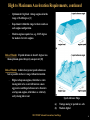
Tuning Vintage Corvette Engines for Maximum
Performance and Fuel Economy
Duke Williams
Southern California Chapter
NCRS San Diego National Convention
July 1, 2012
2012 NCRS National Convention, San Diego
1
Who is this guy?
•
BSME, Univ. of Washington
•
MSME Univ. of Wisconsin
Engine Research Center
•
Cars/bike
Career
Education
•
•
MBA, UCLA
•
Automotive and
aerospace
engineering
•
CAE systems sales
and marketing
•
’76 Cosworth Vega
•
’88 M-B 190E 2.6,
(special order 5- sp.)
•
’91 Toyota MR2
•
’83 Honda CB1100F
Private investor /
philanthropist
’63 Corvette SWC,
L76, M20, G81
(3.08:1)
2012 NCRS National Convention, San Diego
Gone but not forgotten
•
’72 Vega GT
•
’58 TR3 (SCCA E-production)
•
’80 Diesel Rabbit (DEC co. car)
•
’81 Diesel Rabbit (energy crisis
car)
•
’84 M-B 190E 2.3
•
’65 Honda CB160
•
’73 Honda SL350
2
References
noted by [ ] in the slides
1.
Chevrolet Power Manuals, second to fifth editions
10.
Obert, Edward F. Concepts of Thermodynamics
2.
Chevron, Motor Gasolines Technical Review
11.
3.
Dolza, John , The General Motors Fuel Injection
System , SAE paper 570059
Taylor, Charles Fayette, The Internal Combustion Engine
in Theory and Practice, Vols. 1 and 2
12.
Holt, Daniel J., The Chevrolet Corvette New Vehicle
Engineering and Technical History, SAE PT-118
Richardo, Harry, The High Speed Internal Combustion
Engine
13.
Heywood, John B., Internal Combustion Engine
Fundamentals
Richardo, Harry, Memories and Machines: The Pattern of
My Life
14.
Shapiro, Ascher H. The Dynamics and Thermodynamics of
Compressible Fluid Flow
15.
White, Graham, Allied Aircraft Engines of World War II
16.
Williams, Duke, Compression Ratio Explained, The
Corvette Restorer, Vol. 36 No. 2, Summer 2009
17.
Williams, Duke, A Tale of Two Camshafts, The Corvette
Restorer Vol. 37 No.2, Fall 2010
4.
5.
6.
McClellan, Dave, Corvette From the Inside
7.
Schefter, James, All Corvettes Are Red
8.
Strehlow, Roger A. Fundamentals of Combustion
9.
Obert, Edward F. Internal Combustion Engines –
Analysis and Practice
2012 NCRS National Convention, San Diego
3
History of the Spark Ignition Internal IC Engine
•
Not much has changed internally in the last 100 years!
•
The first DOHC 16V engine - a 2-liter inline four - was designed by a Swiss engineer for Peugeot in the
year 1905
•
Twin counter-rotating balance shafts to quell the second order unbalanced vertical shaking force of
inline fours were invented and patented by an Englishman named Lanchester in 1904
•
Technologies like sleeve valves have come and gone
•
The rotary (Wankel) engine made a cameo appearance, but its future is bleak due to emissions and fuel
economy issues
•
Higher octane fuels allow higher compression ratios for greater torque/power and fuel efficiency
•
Better design and analysis tools, better materials, and more precise manufacturing technologies have
allowed a considerable increase in revs for more power
•
Torque bandwidth has been expanded with variable induction system geometry, variable cam phasing,
and even multiple cam lobes for low and high speed (like Honda VTEC)
•
But there has been a big revolution in…
2012 NCRS National Convention, San Diego
4
Engine Management
•
Until the late 1970s
–
Relatively crude mechanical analog controls
• Carburetors with idle, off-idle, cruise, and power fuel metering; cold start enrichment
systems (mechanical chokes)
• Mechanical spark advance controls based on engine revs and load (manifold vacuum)
• Numerous add-on mechanical devices to achieve exhaust emissions standards
beginning in the sixties, which caused many engineers to go prematurely gray
•
Beginning in the late 1970s
–
Development of the oxygen sensor and three-way catalyst opened the door to better
performance and fuel economy while meeting more stringent emissions standards
–
Faster transducers and digital microprocessors allowed increasing engine control
granularity and integration with other power train and vehicle control functions
–
Modern engines continuously adjust and optimize for any fuel octane, air density (due to
temperature and altitude changes), and engine state (cold or fully warmed up)
2012 NCRS National Convention, San Diego
5
Modern Engine Management
Typical Input data
Accelerator position (driver)
Engine speed
Typical output commands
Microprocessor
with
Microprocessor
with
static
static
and
dynamic
and dynamic memory,
memory,
software
software
Spark advance
Manifold pressure
Coolant temperature
Spark
Advance
Maps
Spark
advance
maps
Inlet air temperature
Ambient air pressure
Throttle servo (including idle
speed control)
Injector dwell time
Transmission shift
Fuel
Flow
Maps
Fuel
flow
maps
Vapor canister purge
Mass air flow
Oxygen sensors voltage
Diagnositics
Control
algorithms
Check engine light/fault codes
Crankshaft position
Transmission gear
Diagnostics
Detonation sensor
Note: Modern systems also integrate ABS and vehicle stability control with additional input sensors
such as accelerometers, wheel speed and yaw rate sensors, and add additional output commands for
throttle modulation and selective brake application
2012 NCRS National Convention, San Diego
6
A Little Thermodynamics
• Idealized heat engine models – adiabatic (no heat transfer)/reversible (an “isentropic” process)
–
Spark ignition engines are usually represented by the Otto cycle
• Heat addition at constant volume
• After some algebraic manipulation of the basic thermodynamic equations we find that
thermal efficiency is a monotonic function of the expansion ratio
• Thermal efficiency = 1 – 1/r k-1
–
r is the expansion ratio, which is theoretically the same as the compression ratio
–
k is the ratio of specific heats (1.4 for air)
–
Thermal efficiency for r = 8:1 is 56.5%; r = 10:1 is 60.2 percent
–
10:1 is 6.5% (60.2/56.5) more efficient than 8:1
across the rev range while consuming
• Bottom line: High compression yields higher torque/power
k −1
1
1
−
r
Thermal= 1 − 1 r k −1
less fuel
Isentropic Otto air cycle, heat addition at constant volume [8]
Corresponding thermal efficiency vs. CR [8]
2012 NCRS National Convention, San Diego
7
Thermodynamics Realities and Conclusions for the Real World
•
•
•
In a typical vintage automotive engine at its most efficient operating point (high load, low revs)
about:
–
1/3 of the fuel’s energy is converted to useful work at the crankshaft
–
1/3 is dissipated by the cooling system
–
1/3 is thrown out the exhaust
Increasing the CR from 8 to 10:1 will increase brake thermal efficiency by 6-10 percent
–
Say 8:1 is 0.30
–
10:1 will be about 0.32-0.33
–
Real world fuel consumption is reduced about 6-10 percent at the same output
–
Real world torque/power increases about 6-10 percent across the range for the same fuel
flow
The bottom line
–
Run as high a compression ratio as your available commercial premium fuel will tolerate
–
As built by Flint, actual CR is typically 0.5 less than advertised
–
Most OE engines do not detonate on available unleaded premium
–
If you let some “engine builder” install flattop pistons and a thick head gasket, your “11:1
engine” will end up at about 9:1, and you will leave a lot of torque/power and fuel economy
on the table, but it will probably run detonation-free on unleaded regular for what that’s
worth, which is less than nothing – because the engine will consume more fuel
2012 NCRS National Convention, San Diego
8
The Business Case
•
•
•
Remember the “Asian financial crisis”, circa 1998/1999?
–
Benchmark West Texas intermediate crude dropped to about $12/barrel
–
Regular unleaded sold for at little as $0.75/gallon in some parts of the country
–
Say regular unleaded cost $1.00/gallon
• Premium unleaded was $1.20/gallon – 20 percent more than regular unleaded
– High compression engines “didn’t pay”
The present day
– Regular unleaded is $4.00 per gallon
– Premium is $4.20 – still an additional $0.20 more, but only 5 percent more than premium
– If you get 6-10 percent better fuel economy for only five percent greater cost, what should
you do?
– Plus you get 6-10 percent better torque/power across the range
– Milton Friedman was wrong – at least in this case – there is a free lunch
Bottom line
– Don’t substantially lower OE compression ratio (L88 and ZL1 excluded)
– If it’s on the high side, a little chamber grinding or a slightly thicker head gasket will do the
job
– .010” thicker head gasket drops CR ~ 0.3; 1 cc more chamber volume 0.2 point (327s)
– Recommendations – maximum, properly measured, and computed [15]
> 10:1 – all base cam small blocks, all hydraulic lifter big blocks
> 10.3 – L-79, Duntov, and McCagh Special camshafts, SHP big blocks
> 10.5:1 – LT-1 camshaft
• See the Fall 2009 Corvette Restorer for how to “manage” your compression ratio [16]
2012 NCRS National Convention, San Diego
9
Fuels
•
Two important characterizations are octane rating and the 10/90 percent distillation points
•
Gasoline is a blend of hundreds of different hydrocarbon species
•
The octane rating of a fuel is its detonation resistance compared to a reference fuel, which is the
percent isooctane in a blend of isooctane and normal heptane (i. e. 100 octane is 100 percent
isooctane; 90 octane is 90 percent isooctane, 10 percent normal heptane)
–
Values above 100 add 1 cc TEL per gallon to 100 percent isooctane (i.e. 101 octane equals 100
percent isooctane plus 1 cc per gallon TEL, 102 octane, 2 cc per gallon TEL, etc.)
•
There are at least four different ways to measure octane, which yield different values
•
Unless you know which one is being discussed, the numbers are meaningless!
•
Research Octane Number (RON) – CFR engine, 212F jacket temp, 125F inlet air temperature
•
Motor Octane Number (MON) CFR engine 212 jacket temp, 300F inlet air temp, greater spark
advance
•
Aviation Method – yields values very close to MON
•
Pump (or Posted) Octane Number (PON), also known AKI (anti-knock index) = (RON + MON)/2
•
The difference between RON and MON is called sensitivity and is typically in the range of 8 - 10
–
RON ~ PON plus 4 to 5
> 87 PON ~ 91 to 92 RON
> 93 PON ~ 97-98 RON
•
Typical 10 and 90 percent distillation points
–
10 percent ~ 100-120F, lower for winter blends than summer blends; 90 percent ~ 300-350F
–
Ethanol boils at 170F
2012 NCRS National Convention, San Diego
10
Combustion
•
•
•
•
•
Gasoline does not normally “explode” in the cylinder
Regular does not “burn faster” than premium in normal combustion
Normal combustion propagation
– Turbulent combustion reaction propagates in a predictable manner across the combustion
chamber at less than sonic velocity
Abnormal combustion (Theory of detonation first developed by Ricardo in the early 1900s)
– Some portion of the unburned mixture does “explode” prior to being consumed by normal
combustion propagation
– The explosion shock wave “rattles’ the engine structure which is the “knock” or “ping” we
hear
– The shock greatly increases heat transfer to the combustion chamber boundaries, which can
rapidly overheat combustion chamber boundaries like pistons and valves
Detonation and preignition are not the same thing
– Preignition can lead to detonation
– Detonation can cause preignition, which tends to intensify detonation
– A positive feedback loop, that, if sustained can lead to failed pistons and valves due to local
overheating
Detonation (a) prior to the unburned mixture being consumed by normal combustion propagation [8]
2012 NCRS National Convention, San Diego
11
Combustion, continued
Pressure-time and pressure change rate,
normal combustion [8]
Pressure-time and pressure rate change,
abnormal combustion (detonation) [8]
Consequences of heavy, sustained detonation
2012 NCRS National Convention, San Diego
12
Combustion, continued
• “Flame speed”
–
Usually measured with quiescent gaseous mixture of a fuel and air in a “bomb” of spherical or
tubular geometry
–
Flame is mostly laminar with a velocity of about 30 ft/sec depending on fuel type and test vessel
geometry
–
“Flame speed” does not adequately describe what’s going on in the cylinder
• Cylinder turbulence increases combustion propagation by up to an order of magnitude
–
Combustion propagation increases exponentially with time
–
Detonation is more likely at lower engine speed since since combustion takes more clock time –
twice as much at 2000 versus 4000 RPM
• For a four-inch bore cylinder requiring 38 degrees spark advance for best power
–
Combustion is complete approximately the same number of degrees ATC as the spark advance
(BTC) required to achieve peak output [10]
–
Average combustion propagation rate is 83 ft/sec at 3000, 166 ft/sec at 6000, 250 ft/sec at 9000
–
Combustion propagation rate begins slow, but increases exponentially with time
–
The less spark advance required to achieve peak output, the more efficient the combustion
chamber [10]
• Conclusions
–
The ragged edge of detonation is often the most efficient operating point under load
–
Light, transient detonation is okay
2012 NCRS National Convention, San Diego
13
Combustion, continued
•
All fuels have an “autoignition” temperature, which is detonation, but also a lag time
•
Quench areas at the far reaches of the chamber cool the end gas, which, in combination with lag
time allows normal flame propagation to complete before detonation occurs
•
A compact, high turbulence combustion chamber is best
•
High turbulence in a compact chamber with quench areas and a centrally mounted spark plug
reduces total combustion propagation time, which approaches more closely to the idealized Otto
cycle
–
Less spark advance is required for peak output and efficiency
–
End gas exposure time to high temperature and pressure is lower, which reduces the
propensity to detonate
[left click on right side image to play movie]
2012 NCRS National Convention, San Diego
14
Combustion, continued
Factors that affect the rate of combustion propagation
Slower
Faster
Low cylinder turbulence
High cylinder turbulence
Lean A/F ratio
Rich A/F ratio
Low mixture density
High mixture density
High exhaust gas dilution
Low exhaust gas dilution
• Factors that contribute to detonation
–
Insufficient fuel octane for the as-built compression ratio
–
Excess spark advance for the operating condition
–
High coolant temperature
–
High inlet air temperature
[break for questions]
• For every engine operating condition there is an optimum spark advance for peak torque/power
and fuel efficiency
• How many operating conditions are there?
• Hint: The throttle is an analog device
2012 NCRS National Convention, San Diego
15
Combustion, continued
• Answer: Infinite
• However from a practical standpoint we can distill it down to three cases
– Idle
– Cruise and light acceleration
– High to maximum acceleration (less than 4-6” manifold vacuum)
Idle Issues
• Low mixture density
• High exhaust gas dilution due to high manifold vacuum and valve overlap
• SHP cams, in particular, generate very high exhaust gas dilution at idle
Idle Requirements
• A rich mixture is required due to high exhaust gas dilution
• Extra spark advance is required beyond initial timing to achieve minimum throttle opening and fuel flow
– If this amount of advance was in the form of only initial timing, the engine would be hard to start
2012 NCRS National Convention, San Diego
16
Idle Requirements, continued
–
High overlap cams require more total idle timing than low overlap cams
–
The range is low 20s to low 30s achieved via the sum of initial and full vacuum advance
• Low overlap cams in the low to mid range
• High overlap cams in the mid to high range
• The vacuum advance control (VAC) should be “locked” at full advance at idle speed/vacuum
–
To ensure the above, the VAC should provide full advance at no less than 2” less than typical
idle vacuum
–
This is the Two-Inch Rule
• Not all OE (non-emission controlled) engines comply with this rule e.g. 1963 L-76, 1965 L-78
–
Result: idle instability and stalling
• Emission controlled engines do not meet The Rule because they need high EGT to promote emission
reactions in the exhaust, but this increases idle fuel consumption
Cruise and Light Acceleration/Hill Climbing Issues
• Low to moderate mixture density
• Moderate to high exhaust gas dilution
• Possible detonation
2012 NCRS National Convention, San Diego
17
Cruise and Light Acceleration/Hill Climbing Requirements
• Lean mixture to minimize fuel consumption
• Extra spark advance below the detonation threshold
• 30 to 56 degree range to cover the full cruise range from about 20 MPH to freeway cruise speed (1000
to 4000 revs depending on engine and gearing)
High to Maximum Acceleration Issues
• High mixture density
• Low exhaust gas dilution
• Maximum power across the rev range
• Possible detonation
High to Maximum Acceleration Requirements
• Spark advance within three degrees of optimum to achieve 99 percent of potential output at all engine
speeds from off-idle to redline
• Detonation may limit the amount of advance, particularly at low revs
• Maximum power advance varies with engine design
– Optimum for vintage small blocks is 36-40 degrees [1]
2012 NCRS National Convention, San Diego
18
High to Maximum Acceleration Requirements, continued
–
Optimum for big block vintage engines is in the
range of 36-40 degrees [1]
–
Experiment within this range for best results on
each engine configuration
–
Modern engines require less, e.g. 22-25 degrees
for modern Corvette engines
Rule of Thumb: If spark advance is about 3 degrees less
than optimum, power drops by one percent [10]
Rule of Thumb: Achieve best power spark advance as
low as possible in the rev range without detonation
–
High overlap cam engines, which have a late
closing inlet valve event will tolerate a more
aggressive centrifugal advance curve than low
overlap cam engines, which have a relatively
early closing inlet event
Spark Advance Maps
(a)
(b)
Vintage analog w/ ported vac. adv.
Modern digital
2012 NCRS National Convention, San Diego
19
Tools of the Trade
2012 NCRS National Convention, San Diego
20
Spark and Fuel Maps for Vintage Corvette Engines
• Data is in service manuals and “Vehicle Information Kits” you can download from
www.gmheritiage.com
• OE engine spark and fuel maps had to meet a wide variety of operating conditions
– Minneapolis in January
– Phoenix in July
– High altitude areas like Denver and Albuquerque
• As a result, the OE setups are conservative!
– Fuel maps are usually richer than necessary to ensure good driveability in high air density
conditions
– Centrifugal spark advance curves are typically “lazy” (slow to advance with revs) to avoid
detonation in hot, high density air
– Most OE VACs are properly speced on non-emission controlled engines with some exceptions
– If emission controlled engines are converted from ported to full time vacuum advance the VAC
will usually need to be changed
– B22 (15”), B20 or B26 (12”), B28 (8”); all provide 16 advance at the crankshaft
• Today, most owners drive their vintage Corvettes in much narrower range of ambient conditions
– So, there is usually considerable opportunity to optimize the spark and fuel maps for better
torque, power, and fuel economy
2012 NCRS National Convention, San Diego
21
283 Era
• 283/220,230,245,250,270 HP engines, the advertised CR is only 9.5:1
– 1957 AMA Specifications state the octane requirement is 87-92 RON (82-88 PON)
• These engines might operate satisfactorily on 87 PON unleaded gasoline with the OE spark
advance map
– The centrifugal spark advance map in the 1957 AMA specs, stated in distributor degrees and RPM,
is suspect.
• Reliable sources say it is the same as 1958
• Only the 250 HP Fuel Injection system had vacuum advance in 1957
– All would benefit from vacuum advance, which will require replacing the dual point
distributor with a single point configured with a proper VAC for the camshaft
– The 1958 AMA Specifications state the octane requirement is 94-97 RON despite the same CR
• Why?… possible detonation complaints from customers?
• 1957 283/283 HP and 1958 to 1960 283/290 HP engines advertised CR is 10.5:1
– 1957 AMA Specifications state the octane requirement is 96-99 RON
– 1958 AMA Specifications state the octane requirement is 96-100 RON
– 1958 and 1960 AMA Specifications do not specify RON, only “premium”
– The above “high compression” engines should operate satisfactorily with the OE spark advance
map on 91 PON unleaded gasoline
2012 NCRS National Convention, San Diego
22
283 Era, continued
• Most 1957 to 1961 engines, except FI with the Duntov cam have the following spark advance map
– Centrifugal; (crankshaft degrees and RPM): Start (0) @ 600, 14 @ 1500, 28 @ 3700
• Total centrifugal is okay, but it’s lazy
– Vacuum (230 HP): 0 @ 8”, 15.5 @ 15”
• Meets the Two-Inch Rule with manual transmission
• Does it meet the Two-Inch Rule with Powerglide?
– Vacuum (250 HP) 0@ 8”, 24 @ 13.5”
• FI engines can cruise leaner due to more even fuel distribution, so they can tolerate more
cruise advance
• Meets the Two-Inch Rule for manual transmission
• Does it meet the Two-Inch Rule for Powerglide?
– Specified initial timing varies from 4 to 8 degrees depending on engine, but is this enough?
• With 28 degrees centrifugal, 10 initial is required to achieve 38 total WOT spark advance
• 283, 290, 315 HP
– Centrifugal (engine degrees and RPM): Start (0) @ 1000, 5 @ 1500, 22 @ 6000
– No vacuum advance
– Specified initial timing varies from 12 to 18 degrees, which yields 34-40 total WOT spark adv.
• Verify your OE spark advance map, and test to see what it really is
2012 NCRS National Convention, San Diego
23
327 Era
• 1962 SHP/FI advertised CR increased to 11.25:1
– 1962 Owner’s Manual specifies 99-101 RON for SHP/FI engines
• Customer detonation complaints led to “double gasketing” (two .018” shim gaskets) on
SHP/FI engines from mid-1962 through the end of 1963 production (a TSB was published on
the subject)
– This reduced the as-built CR by ~ 0.6 point
– 1963 Owner’s Manual specified RON remained the same as 1962
• 1962 and 1963 centrifugal advance the same for all engines: 0 @ 700, 11 @ 1600, 24 @ 4600
– Lazy and too short for 250/300 HP engines
• 1962 vacuum advance on 250/300 HP, all 1963 engines, 0 @8” 15 @ 15.5”
– Does not meet Two-Inch Rule for 1963 340 HP engine
– 1963 FI engine had ported vacuum advance
• 1964 SHP/FI engines with the “30-30” cam, which has a very late closing inlet valve got a new map
– Centrifugal: 0 @ 700, 15 @ 1500, 24 @ 2350; Vacuum; 0 @4”, 16 @ 8”
– It doesn’t get any better than this
– Good starting point for all mechanical lifter engines
– Recommend the same centrifugal for L-79, but use a 12” VAC
2012 NCRS National Convention, San Diego
24
327 Era, continued
• 327/300 HP engine
– 1962 – 1963 spark advance map changed in ’64, again in ’65 and again in ’66, which carried
over to ’68
• After four tries they finally got it right, albeit lazy
– Centrifugal: 0 @ 700, 15 @ 1500, 30 @ 5100
• Curve is non-linear; most is in by 3500, but it could still be more aggressive
– Vacuum: 0 @ 6”, 16 @ 12”
• Okay for Powerglide/TH400, but manuals can get away with a 15” VAC
Big Blocks
• Typically 28-30 degrees total centrifugal for all, but lazy
• L78 VAC (15”) does not meet Two-Inch Rule
• All L72/71 have ported vacuum advance – convert to full time with 12” VAC
2012 NCRS National Convention, San Diego
25
Exhaust Emission Controlled Engines
• Spark advance and fuel flow maps were set up to meet emission standards, not performance and fuel
economy
• Centrifugal advance is typically short and lazy with insufficient initial timing to achieve best
torque/power spark advance
• Vacuum advance is typically long, but lazy, which can cause detonation climbing grades
• The entire spark advance map was severely retarded to increase EGT in order to achieve oxidation
reactions in the exhaust system and catalyst
• The single catalyst system, beginning in 1975, increased exhaust backpressure by “half and
atmosphere” (~7.5 psi) [5]
– This severely reduces top end power potential due to excess exhaust pumping power
– Modern monolithic catalysts offer a reduction in flow restriction compared to OE bead bed type
• Recommendations – assuming field emission testing is not required
– Convert spark advance to optimized antecedent non-emission controlled engine
• Base engines – 1966-1967 327/300 HP
• SHP small blocks – 1964-1965 SHP/FI
• Hydraulic lifter big blocks – 1966 L36
• SHP big blocks – 1967 L71
– Raise CR to antecedent high compression engine if/when the engine needs a rebuild
2012 NCRS National Convention, San Diego
26
General Approach to the Project
• Verify that distributor is in optimal working order
– No detectible side play in shaft, .002-.007” shaft end play
– Wobble free breaker plate
– Suitable point set for the application (see the Fall 2012 Corvette Restorer magazine)
– The distributor is the most overlooked engine component and may need a “blueprint” overhaul
• Determine OE spark advance map from service manual and AMA specs
• Measure what it actually is on your car – someone may have changed it in the last 50 years!
• Document everything!
• Run a fuel octane test on 9.5:1 CR 283s
• Convert any ported vacuum advance applications to full time and select a VAC that meets the TwoInch Rule
– Idling in neutral for manual transmissions
– Idling in Drive for automatic transmissions (may require a more aggressive VAC than manuals)
– One of the following three will be best for all single point/TI applications
• B22 (15”), B20 /B26(12”), or B28 (8”) ; all provide 16 degrees maximum advance
2012 NCRS National Convention, San Diego
27
General Approach to the Project, continued
• Set initial timing to achieve 38 degrees from the sum of initial and full centrifugal [16]
– Road test for detonation
• If detonation occurs, reduce initial by 2 degrees or increase total centrifugal by 2-4 degrees and reduce
initial the same
• If no detonation, install lightest centrifugal springs
– Road test for detonation
• If detonation is evident, install progressively heavier springs until the detonation is quelled
– Light transient detonation – such as a about one second duration on upshifts is okay
• Estimated optimum and achievable spark advance maps for various engine families
– Base cam small blocks: 28-30 centrifugal all in by 3000-3500,
• 15” VAC for manuals, 12” PG/TH
• Set initial to achieve 36-38 total WOT advance
• 9.5:1 CR 283s may need premium fuel with a more aggressive than OE centrifugal curve
– SHP/FI small blocks: 24-26 centrifugal all in by 2500-3000
• 8” VAC (all mechanical lifter, L82 automatic) 12” (L79/46, L82 manual)
• Set initial to achieve 36-38 total WOT advance
2012 NCRS National Convention, San Diego
28
General Approach to the Project, continued
• Big block (hydraulic lifter): 30-32 all in by 3000-3500
– 12” VAC (okay for PG/TH400?)
– Set initial timing to achieve 36-38 degrees total WOT spark advance
• Big block (SHP) 28-30 all in by 2500-3000
– 12” VAC
– Set initial timing to achieve 36-38 degrees
• All applications
– If the most aggressive map will tolerate 39-40 degrees total WOT via an increase in initial advance –
go for it!
– For any given engine configuration, what you can achieve may vary according to
• Actual CR, which most owners don’t really know
• Typical ambient conditions - altitude, temperature
• Driving conditions – heavy or light traffic, which affects underhood and coolant temperature
• Driver style/habits
– Spring kit – Mr. Gasket 928G; Goggle search for others
– Single point limit bushing – BWD DG3; HEI weight pivot bushing BWD DG13
• Once you have optimized the spark advance map you are ready for…
2012 NCRS National Convention, San Diego
Mr. Gasket 928G
29
Graduate School – The Fuel Flow Map
• General considerations
– Most OE carburetors (non-emission controlled engines) are set up rich at cruise
– Typical WOT metering is excessively rich at low revs, but leans out as revs increase
• Can result in overly lean mixture at the top end of the rev range with massaged heads
• A/F ratio should not be greater than about 13.5:1 at peak revs
– Fuel flow changes approximately with the area change of the fuel flow path
• For metering jets only (Hollys) a two percent increase/decrease in jet diameter yields
about a four percent increase/decrease in flow area
• For metering rod in the jet main carburetors (Carters and Quadrajets) the fuel flow
area is the area of the jet minus the area of the rod
• If the engine shows no lean issues in road testing, the cruise mixture can probably be
leaned out for better fuel economy
• Approach to the project
– Reduce fuel flow area the smallest amount possible per change
• Preferably 2-3 percent, no more than five percent
– With each fuel flow area change, try stiffer metering rod piston springs (which would be a
higher rated power valve on Hollys) to delay enrichment
• Typical OE enrichment begins at 8-6 “ Hg.
2012 NCRS National Convention, San Diego
30
The Fuel Flow Map, continued
– Fuel Injection engines
• Back off the lean stop in 1/8 turn increments until lean surge is detected, then richen back
1/8 turn
• Keep track of where you’re at – write detailed notes on each change
• Test after each change
– Driveway test
• With your foot on the throttle or your hand on the throttle linkage
> Bring revs up from idle to 1500-2000 and back down in 100 RPM increments
> There should be no hesitation or stumbling
> Slight misbehavior can be improved with a richer idle mixture
• Road test
> No cruise hesitation
> Response to small throttle increases should be crisp and clean
• Issues
– This project takes time and patience
– Limited availability of parts for some carburetor families
– www.carburetion.com www.allcarbs.com www.quadrajet.com www.carburetor-parts.com
– Driveline vendors and Goggle search
2012 NCRS National Convention, San Diego
31
Driving Style and Habits
• If you drive around town in second gear all the time, little in this presentation will make much
difference
• An engine operates most efficiency at low revs regardless of load
• Get it into top gear ASAP
– Short shift – 2000 revs
– Keep it in high gear as long as possible
• Even 30-30 cam engines should pull smoothly from 1000 revs in top gear with enough
torque to keep up with normal traffic if they are set up right
• The most aggressive spark advance map that the engine will tolerate will offer new found low end
torque
• With the fuel you save when the road opens up or you come upon a good freeway onramp you can
afford to rev it to the redline
• If detonation occurs in worst case conditions such as heavy traffic in high temperature conditions
– Drive around it
> Shift at higher revs, ease into the throttle
> Run a gear higher than normal
– A little transient detonation in worst case conditions means you have a near optimum spark
advance map
2012 NCRS National Convention, San Diego
32
Graduation – Dyno Testing
• Once you believe you have optimized your “tune” a chassis dynamometer test with a wideband oxygen
sensor to record A/F ratio is an excellent way to verify and, perhaps, further optimize the setup and
document your engine’s performance over the full rev range from off idle to the redline
• Dynojet chassis dynos are best because they are the most common, which allow you to compare your
engine to others that have been tested at different locations and times
• Typically available for $100-150 per hour, and you can get a lot done if:
– You have a well thought out test plan [17]!
• Opportunity to try different initial timing and/or centrifugal springs – and even jets/rods
• Cruise A/F ratio can be measured by holding manifold vacuum constant in the range of 1216” from 1500 up to 3000 to 3500 depending on highway cruise revs
• They aren’t that hard on an engine in good operating condition
– Top gear pulls from 1000 revs to the redline take about 10-15 seconds
• Start with two or, if necessary three initial runs within one to two percent to establish a baseline before
any changes are made
2012 NCRS National Convention, San Diego
33
Dyno Testing, continued
• Important considerations
– Co-ordinate your written test plan with the operator and have him sign off before you commit
– Start the pulls at 1000 revs or less!
– Use your direct drive gear, but be aware of tire speed ratings
• Pulls in gears through the countershaft reduce output about 3 percent
• Automatics require pulls locked in first gear to get the low end performance data
– Keep the fan clutch from engaging
• Can cost 15 lb-ft torque and 10 HP
• Make sure the shop has good external fans
• Keep the engine at 1500 between shortly spaced pulls
• Use a garden sprayer to spritz down the radiator between pulls
– Keep accurate notes on each test (which should mostly conform to your test plan)
– Obtain the test files via email or disk for analysis on your PC with the Dynojet Winprep 7
software that is a free download from the Dynojet web site
2012 NCRS National Convention, San Diego
34