1
Keysight Technologies
U3020AD01
User’s and Service Guide
Notice: This document contains references to Agilent.
Please note that Agilent’s Test and Measurement business
has become Keysight Technologies. For more information,
go to www.keysight.com.
Notices
© Keysight Technologies, Inc.
2011-2014
No part of this manual may be
reproduced in any form or by any
means (including electronic storage
and retrieval or translation into a
foreign language) without prior
agreement and written consent from
Keysight Technologies, Inc. as
governed by United States and
international copyright laws.
Manual Part Number
U3020-90004
Print Date
October 2014
Supersede August 2012
Published in USA
Keysight Technologies Inc.
1400 Fountaingrove Parkway
Santa Rosa, CA 95403
Where to Find the Latest
Information
Documentation is updated
periodically. For the latest information
about these products, including
instrument software upgrades,
application information, and product
information, browse to the following
URL, search for the name of your
product:
http://www.keysight.com/find
Technology Licenses
Warranty
The hard ware and/or software
described in this document are
furnished under a license and may be
used or copied only in accordance
with the terms of such license.
THE MATERIAL CONTAINED IN THIS
DOCUMENT IS PROVIDED “AS IS,” AND IS
SUBJECT TO BEING CHANGED, WITHOUT
NOTICE, IN FUTURE EDITIONS. FURTHER,
TO THE MAXIMUM EXTENT PERMITTED
BY APPLICABLE LAW, KEYSIGHT
DISCLAIMS ALL WARRANTIES, EITHER
EXPRESS OR IMPLIED WITH REGARD TO
THIS MANUAL AND ANY INFORMATION
CONTAINED HEREIN, INCLUDING BUT
NOT LIMITED TO THE IMPLIED
WARRANTIES OF MERCHANTABILITY AND
FITNESS FOR A PARTICULAR PURPOSE.
KEYSIGHT SHALL NOT BE LIABLE FOR
ERRORS OR FOR INCIDENTAL OR
CONSEQUENTIAL DAMAGES IN
CONNECTION WITH THE FURNISHING,
USE, OR PERFORMANCE OF THIS
DOCUMENT OR ANY INFORMATION
CONTAINED HEREIN. SHOULD KEYSIGHT
AND THE USER HAVE A SEPARATE
WRITTEN AGREEMENT WITH WARRANTY
TERMS COVERING THE MATERIAL IN THIS
DOCUMENT THAT CONFLICT WITH THESE
TERMS, THE WARRANTY TERMS IN THE
SEPARATE AGREEMENT WILL CONTROL.
Restricted Rights Legend
If software is for use in the
performance of a U.S. Government
prime contract or subcontract,
Software is delivered and licensed as
“Commercial computer software” as
defined in DFAR 252.227-7014 (June
1995), or as a “commercial item” as
defined in FAR 2.101(a) or as
“Restricted computer software” as
defined in FAR 52.227-19 (June 1987)
or any equivalent agency regulation or
contract clause. Use, duplication or
disclosure of Software is subject to
Keysight Technologies’ standard
commercial license terms, and
non-DOD Departments and Agencies
of the U.S. Government will receive no
greater than Restricted Rights as
defined in FAR 52.227-19(c)(1-2)
(June 1987). U.S. Government users
will receive no greater than Limited
Rights as defined in FAR 52.227-14
(June 1987) or DFAR 252.227-7015
(b)(2) (November 1995), as applicable
in any technical data.
Safety Notices
CAUTION
A CAUTION notice denotes a hazard. It
calls attention to an operating
procedure, practice, or the like that, if
not correctly performed or adhered to,
could result in damage to the product
or loss of important data. Do not
proceed beyond a CAUTION notice
until the indicated conditions are fully
understood and met.
WARNING
A WARNING notice denotes a hazard.
It calls attention to an operating
procedure, practice, or the like that, if
not correctly performed or adhered to,
could result in personal injury or
death. Do not proceed beyond a
WARNING notice until the indicated
conditions are fully understood and
met.
Table of Contents
U3020AD01
Introduction . . . . . . . . . . . . . . . . . . . . . . . . . . . . . . . . . . . . . . . . . . . . . . . . . . . . . . . . . . . . . . . . . . . . 2
Description . . . . . . . . . . . . . . . . . . . . . . . . . . . . . . . . . . . . . . . . . . . . . . . . . . . . . . . . . . . . . . . . . . . . . 3
Verifying the Shipment . . . . . . . . . . . . . . . . . . . . . . . . . . . . . . . . . . . . . . . . . . . . . . . . . . . . . . . . . . . . 3
Network Analyzer Requirements . . . . . . . . . . . . . . . . . . . . . . . . . . . . . . . . . . . . . . . . . . . . . . . . . . . . 3
General Performance. . . . . . . . . . . . . . . . . . . . . . . . . . . . . . . . . . . . . . . . . . . . . . . . . . . . . . . . . . . . . . 4
Power Requirements . . . . . . . . . . . . . . . . . . . . . . . . . . . . . . . . . . . . . . . . . . . . . . . . . . . . . . . . . . . . 4
Environmental Requirements . . . . . . . . . . . . . . . . . . . . . . . . . . . . . . . . . . . . . . . . . . . . . . . . . . . . . 5
Environmental Tests . . . . . . . . . . . . . . . . . . . . . . . . . . . . . . . . . . . . . . . . . . . . . . . . . . . . . . . . . . . 5
Equipment Heating and Cooling . . . . . . . . . . . . . . . . . . . . . . . . . . . . . . . . . . . . . . . . . . . . . . . . . 5
Required Conditions for Accuracy Enhanced Measurement . . . . . . . . . . . . . . . . . . . . . . . . . . . 5
Dimensions and Space Requirements . . . . . . . . . . . . . . . . . . . . . . . . . . . . . . . . . . . . . . . . . . . . 5
Maximum Power Levels and Performance Characteristics. . . . . . . . . . . . . . . . . . . . . . . . . . . . . . . 6
Front and Rear Panel Features . . . . . . . . . . . . . . . . . . . . . . . . . . . . . . . . . . . . . . . . . . . . . . . . . . . . . . 7
System Setup . . . . . . . . . . . . . . . . . . . . . . . . . . . . . . . . . . . . . . . . . . . . . . . . . . . . . . . . . . . . . . . . . . 10
Adding Instruments to the Interface . . . . . . . . . . . . . . . . . . . . . . . . . . . . . . . . . . . . . . . . . . . . . . . 10
Configuring the LAN Interface . . . . . . . . . . . . . . . . . . . . . . . . . . . . . . . . . . . . . . . . . . . . . . . . . . 10
Locating the Instrument. . . . . . . . . . . . . . . . . . . . . . . . . . . . . . . . . . . . . . . . . . . . . . . . . . . . . . . . . 11
Configuring the GPIB Interface . . . . . . . . . . . . . . . . . . . . . . . . . . . . . . . . . . . . . . . . . . . . . . . . . 12
Adding Instruments to the GPIB Configuration. . . . . . . . . . . . . . . . . . . . . . . . . . . . . . . . . . . . . 12
Changing the GPIB Address. . . . . . . . . . . . . . . . . . . . . . . . . . . . . . . . . . . . . . . . . . . . . . . . . . . . 12
Controlling the Test Set and Making Measurements . . . . . . . . . . . . . . . . . . . . . . . . . . . . . . . . 13
Making Measurements and Functional Tests . . . . . . . . . . . . . . . . . . . . . . . . . . . . . . . . . . . . . . . . . 21
Functional Tests . . . . . . . . . . . . . . . . . . . . . . . . . . . . . . . . . . . . . . . . . . . . . . . . . . . . . . . . . . . . . . . 21
Equipment Required. . . . . . . . . . . . . . . . . . . . . . . . . . . . . . . . . . . . . . . . . . . . . . . . . . . . . . . . . . 21
Transmission . . . . . . . . . . . . . . . . . . . . . . . . . . . . . . . . . . . . . . . . . . . . . . . . . . . . . . . . . . . . . . . 23
Service Information . . . . . . . . . . . . . . . . . . . . . . . . . . . . . . . . . . . . . . . . . . . . . . . . . . . . . . . . . . . . . . 25
Troubleshooting . . . . . . . . . . . . . . . . . . . . . . . . . . . . . . . . . . . . . . . . . . . . . . . . . . . . . . . . . . . . . . 25
Troubleshooting the Power Supply . . . . . . . . . . . . . . . . . . . . . . . . . . . . . . . . . . . . . . . . . . . . . . 25
Troubleshooting the Controller Board . . . . . . . . . . . . . . . . . . . . . . . . . . . . . . . . . . . . . . . . . . . . 25
Replaceable Parts . . . . . . . . . . . . . . . . . . . . . . . . . . . . . . . . . . . . . . . . . . . . . . . . . . . . . . . . . . . . . 27
Electrostatic Discharge Protection . . . . . . . . . . . . . . . . . . . . . . . . . . . . . . . . . . . . . . . . . . . . . . . . . . 28
Safety and Information . . . . . . . . . . . . . . . . . . . . . . . . . . . . . . . . . . . . . . . . . . . . . . . . . . . . . . . . . . . 29
Introduction . . . . . . . . . . . . . . . . . . . . . . . . . . . . . . . . . . . . . . . . . . . . . . . . . . . . . . . . . . . . . . . . . . 29
Safety Earth Ground. . . . . . . . . . . . . . . . . . . . . . . . . . . . . . . . . . . . . . . . . . . . . . . . . . . . . . . . . . . . 29
Declaration of Conformity . . . . . . . . . . . . . . . . . . . . . . . . . . . . . . . . . . . . . . . . . . . . . . . . . . . . . . . 29
Statement of Compliance . . . . . . . . . . . . . . . . . . . . . . . . . . . . . . . . . . . . . . . . . . . . . . . . . . . . . . . 29
Before Applying Power. . . . . . . . . . . . . . . . . . . . . . . . . . . . . . . . . . . . . . . . . . . . . . . . . . . . . . . . . . 30
Connector Care and Cleaning Precautions . . . . . . . . . . . . . . . . . . . . . . . . . . . . . . . . . . . . . . . . . . 31
Regulatory Information . . . . . . . . . . . . . . . . . . . . . . . . . . . . . . . . . . . . . . . . . . . . . . . . . . . . . . . . . . . 32
Instrument Markings . . . . . . . . . . . . . . . . . . . . . . . . . . . . . . . . . . . . . . . . . . . . . . . . . . . . . . . . . . . 32
Battery Collection . . . . . . . . . . . . . . . . . . . . . . . . . . . . . . . . . . . . . . . . . . . . . . . . . . . . . . . . . . . . . 33
Electrical Safety Compliance. . . . . . . . . . . . . . . . . . . . . . . . . . . . . . . . . . . . . . . . . . . . . . . . . . . . . 33
EMI and EMC Compliance . . . . . . . . . . . . . . . . . . . . . . . . . . . . . . . . . . . . . . . . . . . . . . . . . . . . . . . 33
Keysight Support, Services, and Assistance. . . . . . . . . . . . . . . . . . . . . . . . . . . . . . . . . . . . . . . . . . . 34
Service and Support Options. . . . . . . . . . . . . . . . . . . . . . . . . . . . . . . . . . . . . . . . . . . . . . . . . . . . . 34
Contacting Keysight. . . . . . . . . . . . . . . . . . . . . . . . . . . . . . . . . . . . . . . . . . . . . . . . . . . . . . . . . . . . 34
Shipping Your Product to Keysight for Service or Repair . . . . . . . . . . . . . . . . . . . . . . . . . . . . . . . 34
Contents-1
Table of Contents
Contents-2
U3020AD01
User’s and Service Guide U3020-90004
1
U3020AD01
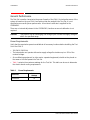
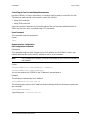
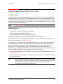
Introduction
Introd uction
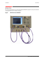
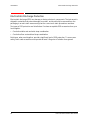
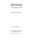
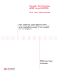
This document describes how to use the Keysight U3020AD01 Dynamic Accuracy Test Set with
a Keysight N5247A PNA-X Network Analyzer.
Figure 1
2
N5247A with the U3020AD01
User’s and Service Guide U3020-90004
U3020AD01
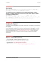
Description
Description
The Keysight U3020AD01 Dynamic Accuracy Test Set is designed for use with the PNA-X
Network Analyzers and based on the L4490A RF Switch Platform.
The U3020AD01 is used to characterize the PNA-X power linearity (dynamic accuracy)
designed for maximum measurement accuracy over a 110 dB dynamic range. The signal is
controlled via internal attenuators.
The U3020AD01 can only be controlled using an external GPIB controller or LAN.
When using Keysight IO Libraries "Connection Expert Utility," the interface identifies the Test
Set as "U3020A" without D01. D01 will be listed on the rear panel serial tag.
Verifying the Shipment
To verify the contents shipped with your product, refer to the “Box Content List” included with
the shipment.
Inspect the shipping container. If the container or packing material is damaged, it should be
kept until the contents of the shipment have been checked mechanically and electrically. If
there is physical damage refer to “Contacting Keysight” on page 34. Keep the damaged
shipping materials (if any) for inspection by the carrier and an Keysight Technologies
representative.
Network Analyzer Requirements
•
The N5247A PNA-X Network Analyzer (10 MHz to 67 GHz)
More PNA-X information is available on the following websites:
•
Documentation - http://www.keysight.com/find/pna
•
Network Analyzer Firmware - http://na.support.keysight.com/pna/firmware
User’s and Service Guide U3020-90004
3
U3020AD01
General Performance
General Performance
The Test Set is used to characterize the power linearity of the PNA-X. Actual performance of the
system is based on the your PNA-X and options that are used with the Test Set. It is not
specified as an overall system performance. A functional certificate is supplied for the
U3020AD01.
There are no internal adjustment in the U3020AD01, therefore an annual calibration is not
required.
This product has an autoranging line voltage input. Be sure the supply voltage is
within the specified range.
CAUTION
Power Requirements
Verify that the required ac power is available at all necessary locations before installing the Test
Set to the PNA-X.
•
100-240 V (50/60 Hz)
•
The instruments can operate with mains supply voltage fluctuations up to ± 10% of the
nominal voltage.
•
Air conditioning equipment (or other motor–operated equipment) should not be placed on
the same ac line that powers the Test Set.
•
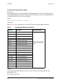
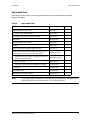
Table 1 contains the maximum wattage for the Test Set. This table can be use to determine
the electrical and cooling requirements.
Table 1
4
Power Requirements
Instrument
Maximum
Wattage
U3020AD01
50
User’s and Service Guide U3020-90004
U3020AD01
General Performance
Environmental Requirements
Refer to the PNA-X standard documentation for environmental requirements.
Environmental Tests
The U3020AD01 complies with all applicable safety and regulatory requirements for the
intended location of use.
•
Operating Environment (Indoor Use)
•
Operating Ambient: Temperature 0 to 40 °C
•
Operating Altitude: 0 to 2000 meters (~ 6,562 feet)
•
The instrument can safely operate in a relative humidity of 80% for temperatures to
31 degrees C, decreasing linearly to 50% relative humidity at 40 degrees C.
Equipment Heating and Cooling
If necessary, install air conditioning and heating to maintain the ambient temperature within the
appropriate range. Air conditioning capacity must be consistent with the rating listed in the
PNA standard documentation.
Required Cond itions for Accuracy Enhanced Measurement
Accuracy–enhanced (error–corrected) measurements require the ambient temperature of the
PNA-X and Test Set to be maintained within ± 1 °C of the ambient temperature at calibration.
Dimensions and Space Requirements
Standard installation of the U3020AD01 and PNA includes configuration and installation on a
customer provided lab bench or table top of adequate size and strength.
Table 2
System Dimensions
Item
Weight
Required Bench Top Dimension:
Clearance above the bench
8.9 cm (3.5 in)
Width
42.5 cm (16.73 in)
Depth
58 cm (22.83 in)
Weight
9 kg (19.84 lb)
User’s and Service Guide U3020-90004
5
U3020AD01
General Performance
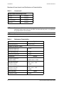
Maximum Power Levels and Performance Characteristics
Table 3
Power Levels
RF Input/Output Power Damage Levels:
SRC 1 IN
+30 dBm
SRC 2 IN
+30 dBm
SRC 2 CPLD OUT
+30 dBm
RCVR OUT
+30 dBm
NOTE
Refer to your PNA-X standard documentation specifications to determine the
maximum input power levels for the PNA-X access and test ports, or to optimize
the power levels in the receivers.
NOTE
Damage and maximum levels are not necessarily the optimum level.
Table 4
Performance Characteristics
Parameter
Operating Frequency
Typical
1 GHz to 4 GHz
Isolation: (1.8 GHz to 2.2 GHz)
RCVR OUT to SRC 1 IN
RCVR OUT to SRC 2 IN
< -45 dB
SRC 1 IN to SRC 2 IN
< -70 dB
RCVR OUT to CPLD OUT
< -80 dB
Transmission:
Nominal
CPLD OUT to SRC 2 IN
(1 GHz to 4 GHz)
-14 dB < trans < -18 dB
SRC 2 IN to RCVR OUT
(1.8 GHz to 2.2 GHz)
(3.5 GHz to 4 GHz)
-3 dB < trans < -9 dB
< -38 dB
SRC 1 IN to RCVR OUT
(1.8 GHz to 2.2 GHz)
(3.5 GHz to 4 GHz)
-3 dB < trans < -9 dB
< -34 dB
Match: (all ports)
1.8 GHz to 2.2 GHz
6
Typical
< -12 dB
User’s and Service Guide U3020-90004
U3020AD01
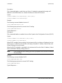
Front and Rear Panel Features
Front and Rear Panel Features
CAUTION
Refer to the standard instrument documentation for damage limits to the ports.
Verify that your test setup will not cause those limits to be exceeded.
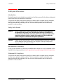
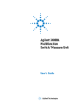
Figure 2
Front Panel
LAN Reset
Attenuation LEDs
Standby
Switch
Instrument State LEDs
SRC 1 IN
RCVR OUT
SRC 2 IN
SRC 2 CPLD OUT
Stand by Switch
Note that this switch is Standby only, not a line switch. The main power cord can be used as the
system disconnecting device. It disconnects the mains circuits from the mains supply.
LAN Reset
The LAN reset button restores the instrument's default LAN configuration.
Attenuation LEDs
The LED’s indicate the attenuation state of the programmable step attenuator.
RF Input/Output
•
SRC 1 IN (Source 1 Input)
•
RCVR OUT (Receiver Out)
•
SRC 2 IN (Source 2 Input)
•
SRC 2 CPLD OUT (Coupler Out)
Instrument State LEDs
When the power is applied to the U3020AD01, the instrument enters its power-on sequence
which requires several seconds to complete. The LEDs provide information on the state of the
instrument during power-on and during upgrades of the instrument firmware. Table 5 identifies
the instrument states based on the color and functioning of the LEDs.
User’s and Service Guide U3020-90004
7
U3020AD01
Table 5
LED
8
Front and Rear Panel Features
LED Definitions and Instrument States
Color
Instrument State
ATTN
LAN
PWR
Off
Green
Green
Instrument in “ready” state
LAN connection established
- instrument has an IP address
Firmware download complete
ATTN
LAN
PWR
flashing
flashing
Green
Power-on/boot-up. ATTN and LAN will flash red and
then green during the power-on self-test.
ATTN
LAN
PWR
Off
Red
Green
No LAN connection due to:
- disconnected LAN cable
- failure to acquire and IP address
- waiting for DHCP-assigned address
ATTN
LAN
PWR
Green (flashing
Green
Green
Instrument Busy State
- firmware download (LAN LED red if download
over GPIB)
- lengthy instrument operation in progress
ATTN
LAN
PWR
Red (flashing
Green
Green
Instrument programming error or self-test error.
Error queue is read using SYSTem:ERRor?
ATTN
LAN
PWR
Off
Green (flashing)
Green
Instrument identification. Activated from instrument
Web interface:
ON: Turn on Front Panel Interface Indicator
OFF: Turn off Front Panel Interface Indicator
User’s and Service Guide U3020-90004
U3020AD01
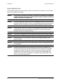
Figure 3
Front and Rear Panel Features
Rear Panel
GPIB
LAN
Line Module
GPIB Connector
This connector allows the Test Set to be connected directly to a controller.
LAN
The instrument is controlled over Local Area Network (LAN).
Line Mod ule
The line module contains the power cord receptacle. The line fuse, as well as a spare, reside
within the line module.
Install the instrument so that the detachable power cord is readily identifiable and is easily
reached by the operator. The detachable power cord is the instrument disconnecting device. It
disconnects the mains circuits from the mains supply before other parts of the instrument. The
front panel switch is only a standby switch and is not a LINE switch. Alternatively, an externally
installed switch or circuit breaker (which is readily identifiable and is easily reached by the
operator) may be used as a disconnecting device.
CAUTION
Always use the three-prong ac power cord supplied with this product. Failure to
ensure adequate grounding by not using this cord may cause damage to the
product.
Power Cords
A line power cord is supplied in one of several configurations, depending on the destination of
the original shipment. Keysight can supply additional certified power cords to meet region
electrical supply and receptacle configurations. Please contact Keysight at: www.keysight.com
for assistance in power cord selection.
WARNING
This is a Safety Class I Product (provided with a protective earthing ground
incorporated in the power cord). The mains plug shall be only be inserted in a
socket outlet provided with a protective earth contact. Any interruption of the
protective cond uctor inside or outside of the product is likely to make the
product dangerous. Intentional interruption is prohibited.
User’s and Service Guide U3020-90004
9
U3020AD01
System Setup
System Setup
Add ing Instruments to the Interface
This section contains information to configure the U3020A LAN and GPIB interfaces using
Keysight IO Libraries “Connection Expert Utility.”
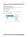
Configuring the LAN Interface
1. Connect the Test Set to the PC.
2. Turn On the Test Set.
3. Select IO Control icon > Keysight Connection Expert from the application window.
Figure 4
10
Keysight Connection Expert
User’s and Service Guide U3020-90004
U3020AD01
System Setup
Locating the Instrument
Keysight Connection Expert opens with a “Welcome Screen,” and a window similar to that
shown in Figure 4. The available computer interfaces are configured during installation of the
Keysight IO Libraries and are displayed in the left column (Explorer Pane). The properties of the
configured interface are displayed in the right column (Propertied Pane).
Figure 5
Explorer and Properties Pane
1. Click Add Instrument on the tool bar to search the network for instruments.
2. Select Add LAN Instrument on LAN (TCPIP0) > OK. Keysight Connection Expert performs an
automatic find of all instruments on the same subnet as the computer.
3. Select the desired instruments from the list and click OK. Communication paths to the
instruments are verified and the instruments are added to the configured interface.
Figure 6
Add ing Instruments
User’s and Service Guide U3020-90004
11
U3020AD01
System Setup
Configuring the GPIB Interface
Programming access to the Test Set is also available through the instrument's GPIB interface.
The GPIB connector is located on the rear panel of the instrument.
1. Select the Keysight Control icon > Keysight Connection Expert. If a GPIB card is installed in
your computer, the GPIB interface was configured during installation of the IO libraries and
is displayed in the Explorer Pane of the “Welcome” Screen.
Figure 7
Keysight Connection Expert
Add ing Instruments to the GPIB Configuration
1. Select Add Instrument on the tool bar.
2. Select GPIB Interface > OK.
3. Select U3020A’s Address in the GPIB address drop-down list >OK.
(Factory set address = 9)
Changing the GPIB Address
The U3020A GPIB address can only be changed programmatically. The GPIB address command
is:
SYSTem:COMMunicate:GPIB:ADDRess <address>
When the address is changed, the new GPIB address is not updated in the Keysight Connection
Expert if the instrument was previously configured.
1. From the Keysight Connection Expert application window, highlight the instrument that's
address was changed and click Change Properties in the Configurable Properties application
window, change the address to the new address setting and select OK.
12
User’s and Service Guide U3020-90004
U3020AD01
System Setup
Controlling the Test Set and Making Measurements
Keysight U3020A is a “slave” instruments. A controller must be used to control the Test Set.
There are two methods that can be used to control the Test Set.
•
Using LAN connection
•
Using GPIB connection
Once the connection between the Controller and the Test Set has been established (LAN or
GPIB), the Test Set can be controlled using SCPI commands.
Reset Command
This command resets the instrument.
Syntax
*RST
Remote Interface Configuration
LAN Configuration Commands
Description
This command assigns a static Internet Protocol (IP) address for the U3020A. Contact your
network administrator for the valid IP address to use for your instrument.
NOTE
If you change the IP address, you must cycle power on the U3020A to activate the
new address.
Syntax
SYSTem:COMMunicate:LAN:IPADdress <address>
SYSTem:COMMunicate:LAN:IPADdress?
You can also queries the U3020A for the IP address it was assigned to.
Example
The following command sets the IP address:
SYST:COMM:IPAD 169.254.149.35
The following query returns the IP address currently being used by the instrument (quotes are
also returned).
SYST:COMM:LAN:IPAD?
Typical Response: "169.254.149.35"
User’s and Service Guide U3020-90004
13
U3020AD01
System Setup
Description
This command disable or enable the use of Auto-IP standard to automatically assign an IP
address to the U3020A when on a network that does not have DHCP servers.
Syntax
SYSTem:COMMunicate:LAN:AUTOip {OFF|0|ON|1}
SYSTem:COMMunicate:LAN:AUTOip?
Example
The following command disable the Auto-IP:
SYST:COMM:LAN:AUTOIP OFF
The following query returns the current Auto-IP setting:
SYST:COMM:LAN:AUTOIP?
Typical Response: 0
Description
This command disables or enables the use of the Dynamic Host Configuration Protocol (DHCP).
Syntax
SYSTem:COMMunicate:LAN:DHCP {OFF|0|ON|1}
SYSTem:COMMunicate:LAN:DHCP?
When DHCP is enable (factory setting), the instrument will try to obtain an IP address from the
DHCP server. If a DHCP server is found, it will assign a Dynamic IP address, Subnet Mask, and
Default Gateway to the instrument.
When the DHCP is disable or unavailable, the instrument will use the Static IP address, Subnet
Mask, and Default Gateway during power-on.
NOTE
If you change the DHCP setting, you must cycle power on the U3020A to activate
the new setting.
Example
The following command disables DHCP:
SYST:COMM:LAN:DHCP OFF
The following query returns the current DHCP setting:
SYST:COMM:LAN:DHCP?
Typical Response: 0
14
User’s and Service Guide U3020-90004
U3020AD01
System Setup
Description
This command assigns the IP address of the Domain Name System (DNS) server. Contact your
network administrator to determine if DNS is being used and for the correct address.
Syntax
SYSTem:COMMunicate:LAN:DNS <address>
SYSTem:COMMunicate:LAN:DNS?
NOTE
If you change the DNS address, you must cycle power on the U3020A to activate
the new address.
Example
The following command sets the DNS address:
SYST:COMM:LAN:DNS 198.105.232.4
The following query returns the DNS address currently being used by the instrument (the
quotes are also returned).
SYST:COMM:LAN:DNS?
Typical Response: "198.105.232.4"
Description
This command assigns a Domain Name to the U3020A. The Domain Name is translated into an
IP address.
Syntax
SYSTem:COMMunicate:LAN:DOMain "<name>"
SYSTem:COMMunicate:LAN:DOMain?
NOTE
If you change the Domain Name, you must cycle power on the U3020A to activate
the new address.
Example
The following command defines the Domain Name:
SYST:COMM:LAN:DOM www.keysight.com
The following query returns the Domain Name currently being used by the instrument:
SYST:COMM:LAN:DOM?
Typical response: www.keysight.com
User’s and Service Guide U3020-90004
15
U3020AD01
System Setup
Description
This command assigns a Default Gateway for the U3020A. The specified IP Address sets the
Default Gateway which allows the instrument to communicate with systems that are not on the
local subnet. Thus, this is the Default Gateway where packets are sent which are destined for a
device not on the local subnet, as determined by the Subnet Mask setting. Contact your
network administrator to determine if a gateway is being used and for the correct address.
Syntax
SYSTem:COMMunicate:LAN:GATEway <address>
SYSTem:COMMunicate:LAN:GATEway?
Example
The following command sets the Default Gateway address:
SYST:COMM:LAN:GATEWAY 255.255.20.11
The following query returns the Default Gateway address currently being used by the
instrument (the quotes are also returned).
SYST:COMM:LAN:GATEWAY?
Typical Response: "255.255.20.11"
Description
This command assigns a Host Name to the U3020A. The Host Name is the host portion of the
domain name, which is translated into an IP address.
Syntax
SYSTem:COMMunicate:LAN:HOSTname "<name>"
SYSTem:COMMunicate:LAN:HOSTname?
NOTE
If you change the Domain Name, you must cycle power on the U3020A to activate
the new address.
Example
The following command defines a Host Name:
SYST:COMM:LAN:HOST "LAB1-U3020A"
The following query returns the Host Name currently being used by the instrument
(the quotes are also returned):
SYST:COMM:LAN:HOST?
Typical Response: "LAB1-U3020A"
16
User’s and Service Guide U3020-90004
U3020AD01
System Setup
GPIB Configuration Commends
Description
This command assigns a GPIB address to the U3020A.
Syntax
SYSTem:COMMunicate:GPIB:ADDRess <address>
SYSTem:COMMunicate:GPIB:ADDRess?
NOTE
If you change the GPIB address, you must cycle power on the U3020A to activate
the new address.
Example
The following command sets the GPIB address to 10:
SYST:COMM:GPIB:ADDR 10
The following query returns the current GPIB address:
SYST:COMM:GPIB:ADDR?
Typical Response: 10
NOTE
For a complete list of SCPI commands, refer to the Keysight L449xA RF Switch
Platform User’s Guide (L4490-90001)
User’s and Service Guide U3020-90004
17
U3020AD01
System Setup
Controlling Test Set Attenuator Settings
Description
This command executes the specified factory defined sequence from the non-volatile memory.
If the specified sequence name not currently stored in the memory, due to corrupted program or
accidentally deleted, an error will be generated.
Syntax
ROUTe:SEQuence:TRIGger <command>
Parameters
Refer to Table 6 for commands use to control the Test Set’s programmable attenuator.
Table 6
Programmable Attenuator Commands
Commands
Description
Explanatory Remarks
ATT1_00
Attenuator setting = 0 dB
ATT1_10
Attenuator setting = 10 dB
ATT1_20
Attenuator setting = 20 dB
ATT1_30
Attenuator setting = 30 dB
ATT1_40
Attenuator setting = 40 dB
ATT1_50
Attenuator setting = 50 dB
ATT1_60
Attenuator setting = 60 dB
LED on the front panel will
indicate current attenuator
setting.
ATT1_70
Attenuator setting = 70 dB
ATT1_80
Attenuator setting = 80 dB
ATT1_90
Attenuator setting = 90 dB
ATT1_100
Attenuator setting = 100 dB
ATT1_110
Attenuator setting = 110 dB
ATT1_CARD1
10 dB Attenuator Bank On
ATT1_CARD2
20 dB Attenuator Bank On
ATT1_CARD3
40 dB Attenuator 1st Bank On
ATT1_CARD4
40 dB Attenuator 2nd Bank On
LED_ALL
All LEDs On
LED_OFF
All LEDs Off
Example
The following executed a sequence name "ATT1_00" which set the programmable step
attenuator to 0 dB.
ROUT:SEQ:TRIG ATT1_00
18
User’s and Service Guide U3020-90004
U3020AD01
System Setup
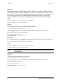
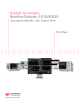
Theory of Operation
This section provides a general description of the U3020A Dynamic Accuracy Test Set. This is
followed by a more detailed operating theory. The operation of each group is described briefly to
the assembly level only. Detailed component level circuit theory is not provided.
Dynamic Accuracy Test Set System Operation
Figure 8 illustrates the components and interconnects of the Dynamic Accuracy Test Set.
The main function of this Test Set is to measure receiver's relative power linearity of the network
analyzer. The Test Set consists of four main components: a controller module, a 39495EXT
module, distribution board for programmable step attenuator, and a front panel LED indicator.
Block Diagram for Dynamic Accuracy Test Set
L4490A
Cntrl Bus
Main
Power
On/Off
U3020A-D01 Dynamic Accuracy Test Set 1 – 4 GHz
LAN
GPIB
Figure 8
Controller Module
and Power Supply
34989-66503 KOM
Switch/Attn Control
Distribution Board
34945EXT
Switch / Attenuator
Driver
Y1153A
Bank 4
P101
I/O
PCB1
I/O Distribution
ISO1
AT1
PCB2
LED Attn
(Frt.Pnl)
ISO2
PD1
ISO3
ISO4
AT1
DC1
SRC 1 IN
RCVR OUT
User’s and Service Guide U3020-90004
SRC 2 IN
SRC CPLD OUT
19
U3020AD01
System Setup
Controller Mod ule
Inside the controller module there are two main components, the AC-DC power supply and
controller board. The AC-DC power supply is a 12V/65W power supply that is converted to
various voltages by means of DC-DC converter inside the module. It provides regulated
voltages to all assemblies in the Test Set as well as following voltages to drive programmable
step attenuator in the Test Set. The internal DC voltage has the following specification:
•
+24V/0.6A
•
+12V/3A fuse
•
+5V/1A
The controller board is the “brain” of the Test Set, it handles all the communication between the
Controller and the Test Set via LAN or GPIB connectivity. Refer to “Controlling the Test Set and
Making Measurements” on page 13.
39495EXT Module
This module drives the programmable step attenuators. The attenuators are connected to the
Test Set through the distribution board (Y1153A), which is installed on the 34945EXT module.
The 34945EXT is divided into four banks, organized by channel number. Any distribution board
may be installed in any bank, and multiple distribution boards of the same type may be installed
on the same 34495EXT module.
Distribution Board
The distribution board provides an interface between the 34945EXT module and the
programmable step attenuator. Depending on the model number and attenuator, a suitable
distribution board will be use.
LED Ind icator Board
This board provides an LED indication of the attenuator setting in the Test Set. The LED
indicator board is driven by the digital IO of the Test Set.
20
User’s and Service Guide U3020-90004
U3020AD01
Making Measurements and Functional Tests
Making Measurements and Functional Tests
Functional Tests
Functional testing consists of measuring transmission insertion loss, return loss, and isolation
between all ports. For the most accurate measurements, the use of an Keysight PNA Network
Analyzer is recommended and its use is assumed in these notes. Familiarity with RF/microwave
measurements is also assumed. The use of adapters may be required and their effects should be
accounted within the measurements.
NOTE
Table 8 on page 27 may be duplicated to record the results of the functional tests.
Equipment Required
•
Keysight PNA-X Network Analyzer (or equivalent)
•
Test Port Extension Cables and Adapters
•
85032B Calibration Kit (50 W, Type-N or equivalent)
There are no adjustments required for the Keysight U3020AD01 Test Set.
The U3020AD01 Test Set is designed to be placed near the network analyzer on a bench top
and connected as shown in Figure 1 on page 2.
The instrument should be placed so that the detachable power cord is readily identifiable and is
easily reached by the operator. The detachable power cord is the instrument disconnecting
device. It disconnects the mains circuits from the mains supply before other parts of the
instrument. The front panel switch is only a standby switch and is not a LINE switch.
Alternatively, an externally installed switch or circuit breaker (which is readily identifiable and is
easily reached by the operator) may be used as a disconnecting device.
1. Connect a GPIB cable from the controller to the rear panel of the network analyzer. Refer to
Figure 3 on page 9.
2. After the proper front and rear panel connections have been made, turn on the Test Set using
the front panel switch.
NOTE
For accurate repeatable measurements, be sure to let the Test Set warm up for at
least two hours. For the most stable and accurate measurements, leave the Test
Set turned on at all times. Do not touch the power sensor for at least
30 minutes before making measurements.
User’s and Service Guide U3020-90004
21
U3020AD01
Making Measurements and Functional Tests
Set up the network analyzer as follows:
Refer to the standard PNA documentation for adapter removal.
1. Select [Center Frequency] > [2.5 GHz].
2. Select [Frequency Span] > [3 GHz].
Perform a full 4-Port adapter removal calibration at the four test ports of the network analyzer.
(Use a Type-N female-to-female adaptor for the transmission calibration).
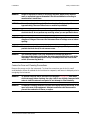
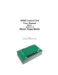
Figure 9
Connecting the Test Set to the Network Analyzer
10 MHz to 20 GHz
N5230C
PNA Series Network Analyzer
GPIB/LAN
PORT 1
RCVR
A IN
CPLR
THRU
CPLR
ARM
SOURCE
OUT
PORT 2
RCVR
B IN
CPLR
THRU
CPLR
ARM
SOURCE
OUT
PORT 3
PORT 4
RCVR
C IN
CPLR
THRU
CPLR
ARM
SOURCE
OUT
RCVR
D IN
CPLR
THRU
CPLR
ARM
SOURCE
OUT
Controller
U3020AD01
ATTENUATION
Dynamic Accuracy Test Set
10 dB
SRC 1 IN
RCVR OUT
SRC 2 IN
SRC 2 CPLD OUT
20 dB
40 dB
40 dB
NOTE
22
In this example we are using a 4-Port PNA-L. A 2-Port PNA can also be used.
User’s and Service Guide U3020-90004
U3020AD01
Making Measurements and Functional Tests
Transmission
1. Connect the cable attached to PORT 1 of the network analyzer to “SRC 1 IN” of the Test Set.
2. Connect the cable from PORT 2 of the network analyzer to “SRC 2 IN” of the Test Set.
3. Connect the cable from PORT 3 of the network analyzer to the “RCVR OUT” of the Test Set.
4. Connect the cable from PORT 4 of the network analyzer to “SRC 2 CPLD OUT” of the Test
Set.
5. Set up the Test Set with the attenuators at 0 dB. Execute the following command over GPIB:
ROUT:SEQ:TRIG ATT1_00
For complete information on controlling the Test Set, refer to “Controlling the Test Set and
Making Measurements” on page 13.
6. Set up the network analyzer to measure S31.
7. Measure the amplitude at 2 GHz and record the value in Table 7 on page 24.
8. Measure the amplitude at 3.5 GHz and record the value.
9. Step through all of the attenuator CARDS (att1_card1, card2, card3, and card4), using the
commands listed in Table 6 on page 18. Verify that all of the attenuator cards are functioning
correctly. ROUT:SEQ:TRIG att1_cardX <command>
10.Repeat step 6 through step 9 measuring S32 (SRC 2 to RCVR OUT).
11.Verify the isolation and match for all ports.
User’s and Service Guide U3020-90004
23
U3020AD01
Table 7
Making Measurements and Functional Tests
Test Record
Parameter
Nominal
Measured Results
Operating Frequency
1 GHz to 4 GHz
Isolation: (1.8 GHz to 2.2 GHz)
RCVR OUT to SRC 1 IN
RCVR OUT to SRC 2 IN
< -45 dB
SRC 1 IN to SRC 2 IN
< -70 dB
RCVR OUT to CPLD OUT
< -80 dB
Transmission:
Nominal
CPLD OUT to SRC 2 IN
(1 GHz to 4 GHz)
-14 dB < trans < -18 dB
SRC 2 IN to RCVR OUT
(1.8 GHz to 2.2 GHz)
(3.5 GHz to 4 GHz)
-3 dB < trans < -9 dB
< -38 dB
______________________
SRC 1 IN to RCVR OUT
(1.8 GHz to 2.2 GHz)
(3.5 GHz to 4 GHz)
-3 dB < trans < -9 dB
< -34 dB
______________________
______________________
Typical
Match: (all ports)1
1.8 GHz to 2.2 GHz
______________________
< -14 dB
1. Port match may be effected by the test port cable. The Test Set and RF cable are included in your
shipment.
24
User’s and Service Guide U3020-90004
U3020AD01
Service Information
Service Information
There are many other repair and calibration options available from the Keysight Technologies
support organization. The options cover a range of service agreements with varying response
times. Contact Keysight for additional information on available service agreements for this
product.
WARNING
These servicing instructions are for use by qualified personnel only. To avoid
electrical shock, do not perform any servicing unless you are qualified to do so.
Troubleshooting
This section contains information for troubleshooting the Test Set to the assembly level only. By
following these procedures, you may determine if the power supply, front panel, or main switch
board needs replacing. Refer to Figure 8, “Block Diagram for Dynamic Accuracy Test Set,” as an
aid in troubleshooting.
NOTE
Refer to the L449xA Service manual for lower level component replacement.
NOTE
If you need to disassemble the instrument, be sure to work at an antistatic
workstation and use a grounded wrist strap to prevent damage from electrostatic
discharge (ESD).
Troubleshooting the Power Supply
Turn the instrument on. Verify the condition of the LED on the front panel:
1. Check the cable and connections between the main board and front panel board.
2. If the cable and connections are working and the LED is still off, there is still a possibility that
the power supply is not supplying the necessary +24 V, +12 V, and +5 V to the main board.
Disconnect the dc power cable from the power supply to the main switch board and measure
the voltages. They should be +24 V, +12 V, and +5 V. If not, replace the power supply.
Troubleshooting the Controller Board
Turn the instrument power on and verify the following:
1. Check the LED display for the model/option and revision information; if there is no backlite
or horizontal/vertical lines are missing, verify that the power supply is working properly, if so
replace the LED display.
2. If there is no information or the information is scrambled, replace the controller board.
3. Verify the switching paths by issuing commands to switch each of the paths. Ensure that the
LED indicates the appropriate path.
User’s and Service Guide U3020-90004
25
U3020AD01
Figure 10
Service Information
U3020AD01 (top view)
Power
Supply
Attenuator
Controller
Isolator (x4)
Attenuator
26
Power Divider
Coupler
User’s and Service Guide U3020-90004
U3020AD01
Service Information
Replaceable Parts
Special options are built to order, long lead times may be encountered when ordering
replacement parts.
Table 8
Replaceable Parts
Replacement Part
Part Number
Power divider, 1 to 26.5 GHz
0955-1421
1
Microwave Coax Isolator (SMA f - f)
0955-2284
4
RF Connector (SMA male, straight 50 Ohm)
1810-0118
1
Attenuator
33322-60010
1
Bulkhead Connector, 3.5 mm
5062-6618
4
Coupler
5087-7729
1
Cable, RF 50 Ohm (3.5MM-3.5MM), 24" long
8121-2111
4
2U RF Switch Platform with Integrated Switch Driver,
includes 64 Switch Drive lines with Option 004
L4490A-CFG002
1
Extender Driver for 34945A, 1 required for each 64
coils with standard option
34945EXT-CFG001
1
PCA, Front Panel
34989-66502
1
Assembly, controller Box for L4490A and L4491A
L4490-60001
1
LED Board
N5261-63005
1
Distribution Card
Y1153-66501
1
Attenuator LED Interface Board
U3020-63114
1
NOTE
Qty
Before replacing an assembly or board, inspect the assembly for obvious, easily
repaired defects such as bent pins on ICs or cold solder joints.
User’s and Service Guide U3020-90004
27
U3020AD01
Electrostatic Discharge Protection
Electrostatic Discharge Protection
Electrostatic discharge (ESD) can damage or destroy electronic components. The instrument is
shipped in materials that prevent damage from static, and should only be removed from the
packaging in an anti-static area ensuring that the correct anti-static precautions are taken.
Two types of ESD protection are listed below. Purchase acceptable ESD accessories from your
local supplier.
•
Conductive table-mat and wrist-strap combination
•
Conductive floor-mat and heal-strap combination
Both types, when used together, provide a significant level of ESD protection. To ensure user
safety, static-safe accessories must provide at least 1 Meg ohm of isolation from ground.
28
User’s and Service Guide U3020-90004
U3020AD01
Safety and Information
Safety and Information
Introduction
Review this product and related documentation to familiarize yourself with safety markings and
instructions before you operate the instrument.
This product has been designed and tested in accordance with accepted industry standards,
and has been supplied in a safe condition. The documentation contains information and
warnings that must be followed by the user to ensure safe operation and to maintain the
product in a safe condition.
Safety Earth Ground
WARNING
This is a Safety Class I Product (provided with a protective earthing ground
incorporated in the power cord). The mains plug shall only be inserted in a
socket outlet provided with a protective earth contact. Any interruption of the
protective cond uctor inside or outside of the product is likely to make the
product dangerous. Intentional interruption is prohibited.
CAUTION
Always use the three prong AC power cord supplied with this product. Failure to
ensure adequate earth grounding by not using this cord may cause product
damage and the risk of electrical shock.
Declaration of Conformity
A copy of the Declaration of Conformity is available upon request, or a copy is available on the
Keysight Technologies web site at http://regulations.corporate.keysight.com/DoC/search.htm
Statement of Compliance
This product has been designed and tested in accordance with accepted industry standards,
and has been supplied in a safe condition. The documentation contains information and
warnings that must be followed by the user to ensure safe operation and to maintain the
product in a safe condition.
User’s and Service Guide U3020-90004
29
U3020AD01
Safety and Information
Before Applying Power
Verify that the premises electrical supply is within the range of the instrument. The instrument
has an autoranging power supply.
WARNING
If this prod uct is not used as specified, the protection provided by the equipment
could be impaired. This product must be used in a normal cond ition (in which all
means for protection are intact) only.
CAUTION
The Mains wiring and connectors shall be compatible with the connector used in
the premise electrical system. Failure, to ensure adequate earth grounding by not
using the correct components may cause product damage, and serious injury.
CAUTION
Always use the three prong AC power cord supplied with this product. Failure to
ensure adequate earth grounding by not using this cord may cause product
damage and the risk of electrical shock.
CAUTION
This product is designed for use in Installation Category II and Pollution Degree.
CAUTION
Before switching on this instrument, make sure the supply voltage is in the
specified range.
CAUTION
Verify that the premise electrical voltage supply is within the range specified on
the instrument.
CAUTION
Ventilation Requirements: When installing the instrument in a cabinet, the
convection into and out of the instrument must not be restricted. The ambient
temperature (outside the cabinet) must be less than the maximum operating
temperature of the instrument by 4 °C for every 100 watts dissipated in the
cabinet. If the total power dissipated in the cabinet is greater than 800 watts,
forced convection must be used.
30
User’s and Service Guide U3020-90004
U3020AD01
Safety and Information
WARNING
Danger of explosion if battery is incorrectly replaced. Replace only with the
same or equivalent type recommended. Discard used batteries accord ing to
manufacturer’s instructions.
WARNING
For continued protection against fire hazard replace line fuse only with same
type and rating. The use of other fuses or material is prohibited.
WARNING
These servicing instructions are for use by qualified personnel only. To avoid
electrical shock, do not perform any servicing unless you are qualified to do so.
WARNING
The opening of covers or removal of parts is likely to expose the user to
dangerous voltages. Disconnect the instrument from all voltage sources before
opening.
WARNING
No operator serviceable parts inside. Refer servicing to qualified personnel. To
prevent electrical shock, do not remove covers.
WARNING
The detachable power cord is the instrument d isconnecting device. It
d isconnects the mains circuits from the mains supply before other parts of the
instrument. The front panel switch is only a stand by switch and is not a LINE
switch (d isconnecting device).
Connector Care and Cleaning Precautions
Remove the power cord to the instrument. To clean the connectors use alcohol in a well
ventilated area. Allow all residual alcohol moisture to evaporate, and fumes to dissipate prior to
energizing the instrument.
WARNING
To prevent electrical shock, d isconnect the Keysight U3020AD01 from mains
electrical supply before cleaning. Use a dry cloth or one slightly dampened with
water to clean the external case parts. Do not attempt to clean internally.
WARNING
If flammable cleaning materials are used, the material shall not be stored, or left
open in the area of the equipment. Adequate ventilation shall be assured to
prevent the combustion of fumes, or vapors.
User’s and Service Guide U3020-90004
31
U3020AD01
Regulatory Information
Regulatory Information
This section contains information that is required by various government regulatory agencies.
Instrument Markings
The instruction documentation symbol. The product is marked with this symbol when it is
necessary for the user to refer to the instructions in the documentation.
The AC symbol indicates the required nature of the line module input power.
This symbol indicates separate collection for electrical and electronic equipment, mandated
under EU law as of August 13, 2005. All electric and electronic equipment are required to be
separated from normal waste for disposal (Reference WEEE Directive, 2002/96/EC).
This symbol indicates that the power line switch is ON.
This symbol indicates that the power line switch is in the STANDBY position.
This symbol indicates that the power line switch is in the OFF position.
This symbol is used to identify a terminal which is internally connected to the product frame
or chassis.
The CE mark is a registered trademark of the European Community. (If accompanied by a
year, it is when the design was proven.)
The CSA mark is a registered trademark of the CSA International.
This mark designates the product is an Industrial Scientific and Medical Group 1 Class A
product (reference CISPR 11, Clause 5)
ICES/NMB-001
This is a marking to indicate product compliance with the Canadian Interference-Causing
Equipment Standard (ICES-001).
Direct Current.
IP 2 0
The instrument has been designed to meet the requirements of IP 2 0 for egress and
operational environment.
The RCM mark is a registered trademark of the Australian Communications and Media
Authority
Indicates the time period during which no hazardous or toxic substance elements are
expected to leak or deteriorate during normal use. Forty years is the expected useful life of
the product.
This symbol on all primary and secondary packaging indicates compliance to China
standard GB 18455-2001.
South Korean Certification (KC) mark; includes the marking's identifier code which follows
the format: MSIP-REM-YYY-ZZZZZZZZZZZZZZ.
32
User’s and Service Guide U3020-90004
U3020AD01
Regulatory Information
Battery Collection
Do not throw batteries away but collect as small chemical waste, or in accordance with your
country’s requirements. You may return the battery to Keysight Technologies for disposal. Refer
to “Contacting Keysight” on page 34 for assistance.
Electrical Safety Compliance
SAFETY
Complies with European Low Voltage Directive 2014/35/EU
•
IEC/EN 61010-1:2010, 3rd Edition
•
Canada: CSA C22.2 No. 61010-1-12
•
USA: UL std no. 61010-1, 3rd Edition
•
Acoustic statement (European Machinery Directive 2022/42/EC, 1.7.4.2U)
Accoustical noise emission
LpA<70 dB
Operator position
Normal operation mode
Per ISO 7779
EMI and EMC Compliance
EMC
Complies with European EMC Directive 2014/30/EU
•
IIEC 61326-1:2012/EN 61326-1:2013
•
CISPR Pub 11 Group 1, class A
•
AS/NZS CISPR 11:2011
•
ICES/NMB-001
This ISM device complies with Canadian ICES-001.
Cet appareil ISM est conforme a la norme NMB du Canada.
•
South Korean Class A EMC declaration: This equipment is Class A suitable for professional
use and is for use in electromagnetic environments outside of the home.
A 급 기기 ( 업무용 방송통신기자재 )이 기기는 업무용 (A 급 ) 전자파적합기기로서 판 매자 또는 사
용자는 이 점을 주 의하시기 바라 며 , 가정외의 지역에서 사용하는 것을 목적으 로 합니다 .
User’s and Service Guide U3020-90004
33
U3020AD01
Keysight Support, Services, and Assistance
Keysight Support, Services, and Assistance
Service and Support Options
There are many other repair and calibration options available from the Keysight Technologies
support organization. These options cover a range of service agreements with varying response
times. Contact Keysight for additional information on available service agreements for this
product.
Contacting Keysight
Assistance with test and measurement needs, and information on finding a local Keysight office
are available on the Internet at:
http://www.keysight.com/find/assist
You can also purchase accessories or documentation items on the Internet at:
http://www.keysight.com/find
If you do not have access to the Internet, contact your field engineer.
NOTE
In any correspondence or telephone conversation, refer to the Keysight product
by its model number and full serial number. With this information, the Keysight
representative can determine the warranty status of your unit.
Shipping Your Prod uct to Keysight for Service or Repair
IMPORTANT
Keysight Technologies reserves the right to reformat or replace the internal hard
disk drive in your analyzer as part of its repair. This will erase all user information
stored on the hard disk. It is imperative, therefore, that you make a backup copy of
your critical test data located on the analyzer’s hard disk before shipping it to
Keysight for repair.
If you wish to send your instrument to Keysight Technologies for service or repair:
•
Include a complete description of the service requested or of the failure and a description of
any failed test and any error message.
•
Remove and retain the front handles and all rack mount hardware. The analyzer should be
sent to Keysight in the same configuration as it was originally shipped.
•
Remove and retain the front handles and all rack mount hardware. The analyzer should be
sent to Keysight in the same configuration as it was originally shipped.
•
Contact Keysight for instructions on where to ship your analyzer.
34
User’s and Service Guide U3020-90004