1
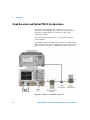
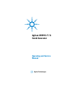
Agilent U9391C/F/G
Comb Generator
Operating and Service
Manual
Agilent Technologies
Notices
© Agilent Technologies, Inc. 2008 - 2013
Warranty
No part of this manual may be reproduced in
any form or by any means (including electronic storage and retrieval or translation
into a foreign language) without prior agreement and written consent from Agilent
Technologies, Inc. as governed by United
States and international copyright laws.
The material contained in this document is provided “as is,” and is subject to being changed, without notice,
in future editions. Further, to the maximum extent permitted by applicable
law, Agilent disclaims all warranties,
either express or implied, with regard
to this manual and any information
contained herein, including but not
limited to the implied warranties of
merchantability and fitness for a particular purpose. Agilent shall not be
liable for errors or for incidental or
consequential damages in connection with the furnishing, use, or performance of this document or of any
information contained herein. Should
Agilent and the user have a separate
written agreement with warranty
terms covering the material in this
document that conflict with these
terms, the warranty terms in the separate agreement shall control.
Manual Part Number
U9391-90001
Edition
Fifth Edition, April 2013
Printed in Malaysia
Agilent Technologies, Inc.
Phase 3 Bayan Lepas Free Industrial Zone
Bayan Lepas, Penang 11900 Malaysia
Technology Licenses
The hardware and/or software described in
this document are furnished under a license
and may be used or copied only in accordance with the terms of such license.
Restricted Rights Legend
U.S. Government Restricted Rights. Software and technical data rights granted to
the federal government include only those
rights customarily provided to end user customers. Agilent provides this customary
commercial license in Software and technical data pursuant to FAR 12.211 (Technical
Data) and 12.212 (Computer Software) and,
for the Department of Defense, DFARS
252.227-7015 (Technical Data - Commercial
Items) and DFARS 227.7202-3 (Rights in
Commercial Computer Software or Computer Software Documentation).
2
Safety Notices
CAUTION
A CAUTION notice denotes a hazard. It calls attention to an operating procedure, practice, or the like
that, if not correctly performed or
adhered to, could result in damage
to the product or loss of important
data. Do not proceed beyond a
CAUTION notice until the indicated
conditions are fully understood and
met.
WA R N I N G
A WARNING notice denotes a
hazard. It calls attention to an
operating procedure, practice, or
the like that, if not correctly performed or adhered to, could result
in personal injury or death. Do not
proceed beyond a WARNING
notice until the indicated conditions are fully understood and
met.
Agilent U9391C/F/G Comb Generator Operating and Service Manual
Certification
Agilent Technologies certifies that this product met its
published specifications at the time of shipment from the
factory. Agilent Technologies further certifies that its
calibration measurements are referenced to the United States
National Institute of Standards and Technology (NIST,
formerly NBS), to the extend allowed by the Institute’s
calibration facility, and to the calibration facilities of the
other International Standards Organization members.
WEEE Compliance
This product complies with the WEEE Directive
(2002/96/EC) marking requirements. The affixed label
indicates that you must not discard this electrical/electronic
product in domestic household waste.
Product Category: With reference to the equipment types in
the WEEE Directive Annex I, this product is classed as a
"Monitoring and Control Instrumentation" product.
Do not dispose in domestic household waste.
To return unwanted products, contact your local Agilent
office, or see www.agilent.com for more information.
Agilent U9391C/F/G Comb Generator Operating and Service Manual
3
Contacting Agilent
For more information, please contact your nearest Agilent
office.
Americas
Canada
Latin America
United States
(877) 894-4414
305 269 7500
(800) 829-4444
Asia Pacific
Australia
China
Hong Kong
India
Japan
Korea
Malaysia
Singapore
Taiwan
Thailand
1 800 629 485
800 810 0189
800 938 693
1 800 112 929
81 426 56 7832
080 769 0800
1 800 888 848
1 800 375 8100
0800 047 866
1 800 226 008
Europe
Austria
Belgium
Denmark
Finland
France
Germany
Ireland
Italy
Netherlands
Spain
Sweden
Switzerland(French)
Switzerland(German)
United Kingdom
Other European Countries:
0820 87 44 11
32 (0) 2 404 93 40
45 70 13 15 15
358 (0) 10 855 2100
0825 010 700
01805 24 6333
1890 924 204
39 02 92 60 8484
31 (0) 20 547 2111
34 (91) 631 3300
0200-88 22 55
41 (21) 8113811 (Opt 2)
0800 80 53 53 (Opt 1)
44 (0) 118 9276201
www.agilent.com/find/contactus
Or, go to www.agilent.com/find/assist for more information.
4
Agilent U9391C/F/G Comb Generator Operating and Service Manual
Contents
1
Introduction
7
Product Overview 8
Key Features of Agilent U9391C/F/G Comb Generator
Compatible Agilent Network Analyzer 11
Options 11
Service and Recertification 12
2
Installation
13
Initial Inspection
14
Operating and Safety Precautions
ESD Damage 16
16
Comb Generator and Agilent PNA-X Configurations
Alternative Configuration with Squaring Circuit
3
Specification
10
18
19
21
General Specifications 22
Drive Power Supply Specifications
Physical Specifications 23
Specifications 23
Mechanical Characteristic
Pin Depth 25
22
25
Environmental Specifications
32
Compliance Notices and Regulatory Information 33
Compliance With Electromagnetic Compatibility (EMC)
Regulatory Markings 33
Declaration of Conformity
33
34
Agilent U9391C/F/G Comb Generator Operating and Service Manual
5
4
Operating Guides
35
Operating Instruction 36
Operator’s Check 36
Service Instructions 44
6
Agilent U9391C/F/G Comb Generator Operating and Service Manual
Agilent U9391C/F/G Comb Generator
Operating and Service Manual
1
Introduction
Product Overview 8
“Key Features of Agilent U9391C/F/G Comb Generator” on page 10
“Compatible Agilent Network Analyzer” on page 11
“Options” on page 11
“Service and Recertification” on page 12
This chapter provides an overview specifications of the
Agilent U9391C/F/G Comb Generator.
Agilent Technologies
7
1
Introduction
Product Overview
The U9391C/F/G comb generator was designed as a phase
reference standard for the Agilent PNA- X nonlinear vector
network analyzer (NVNA). It was developed to provide
precision phase calibration, referenced to the National
Institute of Standards and Technology (NIST).
NVNA component characterization software converts a
4- port PNA- X with option 510 into an innovative,
high- performance, non- linear network analyzer which uses
U9391C/F/G comb generators as precision phase calibration
standards. Comb generators generate frequency harmonics at
integer multiples of an RF input signal.
Generally, comb generators available in the open market
today are made with SRD diodes, U9391C/F/G comb
generators are based on Agilent InP MMIC technology to
ensure superior phase stability of the combs.
Figure 1-1 U9391C Comb Generator
8
Agilent U9391C/F/G Comb Generator Operating and Service Manual
Introduction
1
Figure 1-2 U9391F Comb Generator
Figure 1-3 U9391G Comb Generator
Agilent U9391C/F/G Comb Generator Operating and Service Manual
9
1
Introduction
The U9391C/F/G comb generator offers the advantage of
wide bandwidth 10MHz to 26.5GHz, 10MHz to 50GHz, and
10MHz to 67GHz output and small minimum tone spacing
(10MHz). When driven by low phase noise sources, this comb
generator will operate at frequencies lower than 10MHz, but
performance is not guaranteed. The input power and
fundamental frequency have lower sensitivity than other
comb generators. This means a comb generator calibrated at
a single power level and frequency can be used across a
wide range of input power. It comes with the option of a
female or male output connector.
U9391C/F/G modules are solid state devices which provide
excellent phase and amplitude flatness in the combs making
them ideal for use in phase calibration applications. A
built- in frequency divider, selectable via the PNA- X, reduces
the noise of the combs. You can set drive frequency at 1, 2,
4, 8 or 16 times the pulse repetition frequency (PRF).
Combining a frequency divider with a wide input signal
frequency range allows for a broad range of possible
harmonics spacing, making this suitable for characterizing
non- linear devices. This module has a trigger output which
enables synchronization with the pulse’s repetition
frequency. Calibration data stored inside the U9391C/F/G
can be accessed directly by the PNA- X via the USB interface
to be used in phase calibration.
Key Features of Agilent U9391C/F/G Comb Generator
• Excellent amplitude and phase flatness enable it to be
used as a precision calibration phase reference standard
for the NVNA.
• NIST referenced phase calibration guarantees a reliable
reference to international standards.
• Embedded calibration data can be easily accessed via the
plug- and- play USB interface.
• The USB interface further facilitates frequency divider
control and calibration data retrieval via the PNA- X.
10
Agilent U9391C/F/G Comb Generator Operating and Service Manual
Introduction
1
• Rugged 1.85mm, 2.4mm, and 3.5mm bulk- head connectors
guarantee high repeatability throughout multiple connects
and disconnects.
• The sine- to- square wave converter provided as standard
accessory (U9391F/G only) ensures the comb generator
functions at its optimum level for output frequencies
above 26.5GHz.
• The hand grip (U9391G only) is designed for better
gripping and as a heat insulator for user’s handling.
Compatible Agilent Network Analyzer
The U9391C/F/G are designed to operate with Agilent
PNA- X nonlinear vector network analyzer (NVNA). The
U9391C/F/G modules are controlled by the PNA- X network
analyzer via a USB connection with options required: 400,
419, 080, 510. PNA- X network analyzers can be upgraded to
perform non- linear component characterization.
Options
There are two connector options available for Agilent
U9391C/F/G.
Table 1-1 Options for Agilent U9391C/F/G
Option
U9391C
U9391F
U9391G
Option FFF
3.5mm Female (Output
connector)
2.4mm Female (Output
connector)
1.85mm Female (Output
connector)
Option FFM
3.5mm Male (Output
connector)
2.4mm Male (Output
connector)
1.85mm Male (Output
connector)
NOTE
The Trigger and Input ports are of 3.5mm Female connectors, for all the
options above.
Agilent U9391C/F/G Comb Generator Operating and Service Manual
11
1
Introduction
Service and Recertification
If your Comb generator modules require service or
recertification, contact the nearest Agilent office for
information on where to send it. Refer to “ Contacting
Agilent” in the front matter of this manual. The performance
of the comb generator modules can only be verified by
specially manufactured equipment and calibration standards
from Agilent.
Recertification of Comb Generator Modules
The suggested interval for recertification is 12 months. After
reviewing the result of the initial recertification, you may
establish a shorter interval that reflects greater use and
wear of the module.
12
Agilent U9391C/F/G Comb Generator Operating and Service Manual
Agilent U9391C/F/G Comb Generator
Operating and Service Manual
2
Installation
Initial Inspection 14
Operating and Safety Precautions 16
“ESD Damage” on page 16
“Connector Care” on page 17
Comb Generator and Agilent PNA-X Configurations 18
“Alternative Configuration with Squaring Circuit” on page 19
This chapter provides you important information on how to
check and prepare your instrument for operation.
Agilent Technologies
13
2
Installation
Initial Inspection
1 Unpack and inspect the shipping container and its
contents throughly to ensure that nothing was damaged
during shipment. If the shipping container or cushioning
material is damaged, the contents should be checked both
mechanically and electrically.
• Check for mechanical damage such as scratches or
dents
• Procedures for checking electrical performance are
given under “Operator’s Check” on page 36.
2 If the contents are damaged or defective, contact your
nearest Agilent Technologies Service and Support Office.
Refer to the Service and Support information in the front
matter of this manual. Agilent Technologies will arrange
for repair or replacement of the damaged or defective
equipment. Keep the shipping materials for the carrier’s
inspection.
3 If you are returning the instrument under warranty or for
service, repackaging the instrument requires original
shipping containers and material or their equivalents.
Agilent Technologies can provide packaging materials
identical to the original materials. Refer to Service and
Support information in the front matter of this manual
for the Agilent Technologies nearest to you. Attach a tag
indicating the type of service required, return address,
model number and serial number. Mark the container
FRAGILE to insure careful handling. In any
correspondence, refer to the instrument by model number
and serial number.
14
Agilent U9391C/F/G Comb Generator Operating and Service Manual
Installation
2
Kit Contents
The following table lists the items in the U9391C/F/G kit.
Table 2-1 U9391C/F/G Kit Contents
QUANTITY
DESCRIPTION
PART NUMBER
*
1
Cable assembly - Banana plug
U9391-20013
1
USB cable
8121-0506
* Compatible cable: 87405-20006
Agilent U9391C/F/G Comb Generator Operating and Service Manual
15
2
Installation
Operating and Safety Precautions
Observe the following guidelines before connecting or operating the Comb Generator
modules.
ESD Damage
Protection against electrostatic discharge (ESD) is important
while handling and operating the Agilent U9391C/F/G
module.
Static electricity can build up on your body and can easily
damage sensitive components when discharged.
Static discharges too small to be felt can cause permanent
damage to the unit.
To prevent damage from ESD:
• Use a grounded antistatic mat in front of your test
equipment and wear a grounded wrist strap attached to it
when handling or operating the Comb Generator module.
• Wear a heel strap when working in an area with a
conductive floor.
• Ground yourself before you clean, inspect or make a
connection to an Comb Generator module. You can, for
example, grasp the grounded outer shell of the analyzer
test port or cable connector briefly.
• Avoid touching the center conductor of the test ports.
16
Agilent U9391C/F/G Comb Generator Operating and Service Manual
Installation
2
Connector Care
Because connectors can become defective due to wear during
normal use, all connectors should be inspected and maintained to maximize their service life.
• Inspect the mating surface each time a connection is
made. Metal particles from connector threads often find
their way onto the mating surface when a connection is
made or disconnected.
• Clean dirt and contamination from the connector mating
surface and threads. This simple step can extend the service
life of the connector and improve the quality of your calibration and measurements.
• Gage connectors periodically. This not only provides
assurance of proper mechanical tolerances, and thus connector performance, but can also indicate situations where
the potential for damage to another connector may exist.
CAUTION
The Agilent Comb Generator modules can be damaged if apply
excessive torque to the connectors.
The recommended torque value is 8lb-in torque.
Agilent U9391C/F/G Comb Generator Operating and Service Manual
17
2
Installation
Comb Generator and Agilent PNA-X Configurations
Two units of U9391C/F/G are required to carry out
non- linear measurements. One unit is used as the phase
reference module and the second unit as the phase
calibration module.
The U9391C/F/G units need to be powered by separate
power supplies.
The NVNA software automatically controls the U9391C/F/G
units via USB after the two units have been selected as the
phase reference and phase calibration module respectively.
Figure 2-1 U9391C/F/G and PNA-X Configuration
18
Agilent U9391C/F/G Comb Generator Operating and Service Manual
Installation
2
The phase calibration procedure is carried out by following
the on- screen instructions on the PNA- X.
After completing the calibration, the U9391C/F/G unit used
for phase calibration can be disconnected. The other unit
that is used as the phase reference will remain connected
while the measurement is carried out.
For more detailed information, please refer to the Help file
that is embedded in the NVNA application.
CAUTION
When connecting the U9391C/F/G directly to the instrument test
ports, the modules will require mechanical support so as not to
overstress the test port connectors.
Alternative Configuration with Squaring Circuit
If a signal generator is not available, the PNA- X 10MHz
reference output located at the back panel can be used as a
signal source. However, the U9391- 60009 sine- to- square
wave converter is required as the comb generator will not
function at its optimum level for output frequencies above
26.5GHz, with a sine wave input of less than 100MHz.
Having said this, the converted 10MHz square wave signal
may portray some reduced calibration accuracy, in
comparison to using the PSG as a source.
Hence, the U9391- 60009 squaring circuit, which is powered
up via USB, is included as a standard accessory for U9391F
and U9391G.
Agilent U9391C/F/G Comb Generator Operating and Service Manual
19
2
Installation
Figure 2-2 U9391F/G and Square Wave Converter Configuration
20
Agilent U9391C/F/G Comb Generator Operating and Service Manual
Agilent U9391C/F/G Comb Generator
Operating and Service Manual
3
Specification
General Specifications 22
“Drive Power Supply Specifications” on page 22
“Physical Specifications” on page 23
“Specifications” on page 23
Mechanical Characteristic 25
“Pin Depth” on page 25
“Typical Pin Depth Values” on page 27
“Mechanical Dimension of the Modules” on page 28
“Mechanical Dimension of the Modules” on page 29
“Mechanical Dimension of the Modules” on page 30
“Mechanical Dimension for Squaring Circuit” on page 31
Environmental Specifications 32
Compliance Notices and Regulatory Information 33
“Compliance With Electromagnetic Compatibility (EMC)” on page 33
“Regulatory Markings” on page 33
Declaration of Conformity 34
This chapter provides an overview specifications of Agilent
U9391C/F/G Comb Generator.
Agilent Technologies
21
3
Specification
General Specifications
Drive Power Supply Specifications
Table 3-1 U9391C/F/G Drive Power Supply Specification
Model
U9391C
U9391F
U9391G
Voltage
+15 ± 10% Vdc
+15 ± 10% Vdc
+15 ± 10% Vdc
Current
300mA (nominal)
300mA (nominal)
850mA (nominal)
NOTE
Recommended DC power supply for U9391C/F: E3620A
Recommended DC power supply for U9391G: E3615A
Compatible DC power supply: All E36XXA series power supply (except
E3612A and E3614A).
Current drawn will change when drive voltage changes.
Figure 3-1 U9391-20013 DC Bias Cable
22
Agilent U9391C/F/G Comb Generator Operating and Service Manual
Specification
3
Physical Specifications
Model
U9391C
U9391F
U9391G
Net weight
0.370kg
0.370kg
0.435kg
Shipping weight
3.155kg
3.315kg
3.385kg
Length
52.5cm
52.5cm
52.5cm
Width
34.0cm
34.0cm
34.0cm
Height
19.5cm
19.5cm
19.5cm
Shipping dimension
Specifications
Specifications refer to the performance standards or limits
against which the U9391C/F/G are tested.
Typical characteristics are included for additional
information only and they are not specifications. These are
denoted as “typical”, “nominal”, or “approximate” and are
printed in italic.
Table 3-2 U9391C/F/G Specifications
Model
U9391C
U9391F
U9391G
Output frequency range*
10MHz to 26.5GHz
10MHz to 50GHz
10MHz to 67GHz
Input frequency range†
10MHz to 6GHz
10MHz to 6GHz
10MHz to 6GHz
Input power range
-15 to +15dBm
-15 to +15dBm
-15 to +15dBm
Min output power per picket
-80dBm at 10MHz Input PRF
-95dBm at 10MHz Input PRF
-100dBm at 10MHz Input PRF
Amplitude flatness vs.
Output frequency
< 12dB at 10MHz Input PRF
< 25dB at 10MHz Input PRF
< 40dB at 10MHz Input PRF
Amplitude flatness vs. input
power
0.1dB (typical)
0.5dB (typical)
1.0dB (typical)
Agilent U9391C/F/G Comb Generator Operating and Service Manual
23
3
Specification
Table 3-2 U9391C/F/G Specifications
Model
U9391C
U9391F
U9391G
Phase flatness‡
+/- 8.5 degrees (10MHz to
3GHz)
+/- 6.5 degrees (3GHz to
20GHz)
+/- 8.5 degrees (20GHz to
26.5GHz)
+10/-10 degrees (10MHz to
28GHz)
+20/-10 degrees (28GHz to
38GHz)
+20/-15 degrees (38GHz to
50GHz)
+10/-10 degrees (10MHz to
26.5GHz)
+20/-10 degrees (26.5GHz to
38GHz)
+20/-15 degrees (38GHz to
50GHz)
+35/-35 degrees (50GHz to
67GHz)
Pulse width (ps)
< 23
< 23
< 23
Divide ratio
1, 2, 4, 8, 16
1, 2, 4, 8, 16
1, 2, 4, 8, 16
Input Return Loss, S11
> 10dB (10MHz to 6GHz)
> 10dB (10MHz to 6GHz)
> 10dB (10MHz to 6GHz)
Output Return Loss, S22
> 10dB (10MHz to 26.5GHz)
> 10dB (10MHz to 20GHz)
> 7dB (20GHz to 45GHz)
> 5dB (45GHz to 50GHz)
> 10dB (10MHz to 20GHz)
> 7dB (20GHz to 45GHz)
> 5dB (45GHz to 67GHz)
* When driven by low phase noise sources, this comb generator will operate at frequencies lower than 10MHz, but performance
is not guaranteed.
† For operations below 100MHz, use a square wave to drive the comb generator.
‡ The specifications refers to the raw performance data. For NVNA application, the phase performance is corrected with the
calibration data.
24
Agilent U9391C/F/G Comb Generator Operating and Service Manual
Specification
3
Mechanical Characteristic
Mechanical characteristics, such as center conductor
protrusion and pin depth are not warranted performance
specifications.
They are however important supplemental characteristics
related to the electrical performance of the devices.
Agilent Technologies verifies the mechanical characteristics
of the devices with special gaging processes and electrical
testing.
These processes ensure that the device connectors do not
exhibit any excess center conductor protrusion or improper
pin depth when the module leaves the factory.
Pin Depth
Pin depth is the distance the center conductor mating plane
differs from being flush with the outer connector mating
plane.
The pin depth of a connector can be in one of two states:
protrusion or recession.
Protrusion occurs when the center conductor extends
beyond the outer conductor mating plane. It reads as a
positive value on the connector gage.
Recession occurs when the center conductor is set back
from the outer conductor mating plane. It reads as a
negative value on the gage.
Agilent U9391C/F/G Comb Generator Operating and Service Manual
25
3
Specification
The pin depth for a 1.85mm, 2.4mm, and 3.5mm connector
is shown in Figure 3- 2.
The typical pin depths for U9391C/F/G connectors are listed
in “Typical Pin Depth Values” on page 27.
Figure 3-2 Pin Depth for a 1.85mm, 2.4mm, and 3.5mm Connectors
26
Agilent U9391C/F/G Comb Generator Operating and Service Manual
Specification
3
Typical Pin Depth Values
The pin depth value of each device is not specified, but is
an important mechanical parameter.
The electrical performance of the device depends, to some
extent, on its pin depth.
The electrical specifications for each module takes into
account the effect of pin depth on the device’s performance.
The following tables list the typical pin depths for the
devices.
Table 3-3 U9391C/F/G Comb Generator Pin Depth Characteristic
Port
Typical Pin Depth in Micrometers
(10-4 inches)
U9391C
In port
Out port
Trigger port
U9391F
U9391G
0 to -50.8
0 to -50.8
0 to -50.8
(0 to -20.0)
(0 to -20.0)
(0 to -20.0)
0 to -50.8
0 to -50.8
0 to -50.8
(0 to -20.0)
(0 to -20.0)
(0 to -20.0)
0 to -127.0
0 to -127.0
0 to -127.0
(0 to -50.0)
(0 to -50.0)
(0 to -50.0)
If the pin depth of a device does not measure within the
observed pin depth limits, it may be an indication that the
device fails to meet electrical specification.
Agilent U9391C/F/G Comb Generator Operating and Service Manual
27
3
Specification
Mechanical Dimension of the Modules
Figure 3-3 Mechanical Dimension of U9391C Comb Generator
28
Agilent U9391C/F/G Comb Generator Operating and Service Manual
Specification
3
Mechanical Dimension of the Modules
Figure 3-4 Mechanical Dimension of U9391F Comb Generator
Agilent U9391C/F/G Comb Generator Operating and Service Manual
29
3
Specification
Mechanical Dimension of the Modules
Dimensions in millimeters and (inches).
Figure 3-5 Mechanical Dimension of U9391G Comb Generator
NOTE
30
The hand grip is designed for the U9391G only for better gripping and as a
heat insulator for user's handling.
Agilent U9391C/F/G Comb Generator Operating and Service Manual
Specification
3
Mechanical Dimension for Squaring Circuit
Dimensions in millimeters and (inches).
Figure 3-6 Mechanical Dimension of U9391-60009 Squaring Circuit
NOTE
The U9391-60009 squaring circuit is available for the U9391F and U9391G only.
Agilent U9391C/F/G Comb Generator Operating and Service Manual
31
3
Specification
Environmental Specifications
Agilent U9391C/F/G are designed to fully comply with
Agilent Technologies’s product operating environment
specifications. The following are the summarized
environmental specifications for these products.
Table 3-4 U9391C/F/G Environmental Specifications
Temperature
• Operating
0°C to +40°C
• Storage
-40°C to +70°C
• Error corrected range
23°C to +/- 3°C
• Cycling
-65°C to +85°C, 10 cycles at 20°C per minute. 20 minutes dwell time per
MIL-STD-883F, Method 1010.8, Condition C (modified)
Relative Humidity
• Operation
50% to 95% RH at 40°C, 24 hours cycling, repeated 5 times
• Storage
90% RH at 65°C, one 24 hour cycle
Shock
• End-use handling shock
Half-sine wave form, 2-3ms duration, 60 in/s (1.6ms) delta-V
• Transportation shock
Trapezoidal wave form, 18-22ms duration, 337 in/s (8.56ms) delta-V
Vibration
• Operating
Random: 5-500Hz, 0.21grms, 10min/axis
• Survival
Random: 5-500Hz, 2.09grms, 10min/axis
Swept Sine: 5-500Hz, 0.5grms, 10min/axis, 4 resonance search, 10min dwell
Altitude
• Operating
< 4,572 meters (15,000 feet)
• Storage
< 15,000 meters (50,000 feet)
ESD immunity:
• Direct discharge*
8.0 kV per IEC 61000-4-2
• Air discharge
15 kV per IEC 61000-4-2
* To outer conductor
32
Agilent U9391C/F/G Comb Generator Operating and Service Manual
Specification
3
Compliance Notices and Regulatory Information
Compliance With Electromagnetic Compatibility (EMC)
This product conforms with the protection requirements of
EMC Directive 2004/108/EC for Electromagnetic
Compatibility.
The product comply to the EMC Directive by assessment
according to IEC/EN61326- 1 EMC standard.
In order to preserve the EMC performance of the product,
any cable which becomes worn or damaged must be replaced
with the same type and specifications.
Refer to the “Declaration of Conformity” on page 34.
Regulatory Markings
The CE mark shows that the product complies with all the
relevant European Legal Directives.
ICES/NMB-001
ICES/NMB-001 indicates that this ISM device complies with
Canadian ICES-001.
Cet appareill ISM est conforme a la norme NMB-001 du Canada.
ISM GRP.1 CLASS A
This is the symbol of an Industrial Scientific and Medical Group
1 Class A product.
ff
N10149
The C-Tick mark is a registered trademark of the Spectrum
Management Agency of Australia. This signifies compliance
with the Australian EMC Framework Regulations under the
terms of the Radio communications Act of 1992.
Agilent U9391C/F/G Comb Generator Operating and Service Manual
33
3
Specification
South Korean Class A EMC declaration:
This equipment is Class A suitable for professional use and is
for use in electromagnetic environments outside of the home.
Declaration of Conformity
A copy of the Manufacturer’s Declaration of Conformity for
this instrument can be obtained by contacting your local
Agilent Technologies sales representative.
34
Agilent U9391C/F/G Comb Generator Operating and Service Manual
Agilent U9391C/F/G Comb Generator
Operating and Service Manual
4
Operating Guides
Operating Instruction 36
“Operator’s Check” on page 36
“Service Instructions” on page 44
This chapter provides you a simple quick- check instruction
to verify Agilent U9391C/F/G Comb Generators’ functionality
prior to usage.
Agilent Technologies
35
4
Operating Guides
Operating Instruction
Operator’s Check
The operator’s check is supplied to allow the operator to
make quick check of the comb generator prior to use or if a
failure is suspected.
CAUTION
ESD exceeding the level specified in Table 3-4 or RF power applied is
greater than the maximum specified as in Table 3-2 may cause
permanent damage to the device.
Operator’s Check for S-Parameter Test
Recommended Test Equipment
Table 4- 1 and Table 4- 2 below lists the test equipment
required for performance test verification. Equipment other
than the recommended models can be used, provided
minimum specifications are satisfied.
Table 4-1 Recommended Test Equipment
Instrument Type
Setting
*
PNA-X Network Analyzer
(option 400, 419, 080, 510)
PNA-X application
•
•
•
•
Start Frequency: 10MHz
Stop Frequency: 26.5GHz/50GHz/67GHz†
Power Level: -20dBm
No of points: 201
For U9391C/F:
E3631A DC Power Supply
• Voltage: +15Vdc
• Current: 2 x 0.3A‡
For U9391G:
E3615A DC Power Supply
36
• Voltage: +15Vdc
• Current: 2 x 0.85A**
Agilent U9391C/F/G Comb Generator Operating and Service Manual
Operating Guides
4
* N5242A, N5244A, N5245A, and N5247A
† 26.5GHz for U9391C, 50GHz for U9391F, and 67GHz for U9391G
‡ To power up 2 units of U9391C/F
** To power up 2 units of U9391G
Quick-Check Procedure
Figure 4-1 Quick-check Configuration for S-parameter Test
Agilent U9391C/F/G Comb Generator Operating and Service Manual
37
4
Operating Guides
The equipment setup is as illustrated in Figure 4- 1.
1 Click on PNA- X application. Calibrate the network
analyzer with full 2- port calibration using the appropriate
electronic or mechanical calibration kit.
2 Connect Input of comb generator to Port 1 of network
analyzer and Output of comb generator to Port 2 of
network analyzer.
3 Turn ON the biasing of the comb generator by connecting
to power supply, +15V, 0.3A for U9391C/F and +15V, 0.85A
for U9391G.
4 Get the measurement for Input Return Loss (S11) and
Output Return Loss (S22).
5 Compare measurement results with specification in
Table 3- 2 on page 23.
Operator’s Check for Nonlinear Vector Network Analyzer
(NVNA) Test
Table 4-2 Recommended Test Equipment
Instrument Type
PNA-X Network Analyzer* (option 400,
419, 080, 510)
Setting
NVNA application
• Start & Stop Frequency: 10MHz
• Frequency points: 1
• Maximum Harmonics:
2650/5000/6700†
For U9391C/F:
E3631A DC Power Supply
• Voltage: +15Vdc
• Current: 2 x 0.3A‡
For U9391G:
E3615A DC Power Supply
• Voltage: +15Vdc
• Current: 2 x 0.85A**
E8267D PSG Signal source or any source • N/A
that can provide 10MHz to 6GHz RF output
38
Power sensor and power meter
• N/A
11636B Power Divider
• N/A
Agilent U9391C/F/G Comb Generator Operating and Service Manual
Operating Guides
4
* N5242A, N5244A, N5245A, and N5247A
† 2650 for U9391C, and 5000 for U9391F, and 6700 for U9391G
‡ To power up 2 units of U9391C/F
** To power up 2 units of U9391G
Figure 4-2 Quick-check Configuration for NVNA Test
Quick-Check Procedure
The equipment setup is as illustrated in Figure 4- 2.
1 Connect GPIB linking PNA- X, PSG and Power Meter.
2 Power up both the phase reference units and also connect
the USB cable to the PNA- X.
3 Shutdown the network analyzer application and turn on
NVNA application. Leaving the network analyzer
application running in the background will cause the
NVNA applications to not function properly.
4 Click Response and select Couple Segment from Agilent
Nonlinear Vector Network Analyzer main menu as shown
in Figure 4- 3.
5 Again, click Response and select Receiver Attenuation.
Set 10dB at Receive B portion and then click OK.
Agilent U9391C/F/G Comb Generator Operating and Service Manual
39
4
Operating Guides
6 Set the parameters as following. Then click Apply button.
a Start and Stop frequency : 10MHz
b Frequency points : 1
c Maximum Harmonics : 2650/5000/6700*
d IFBW : 10Hz
Figure 4-3 NVNA main menu
* 2650 for U9391C, 5000 for U9391F, and 6700 for U9391G
40
Agilent U9391C/F/G Comb Generator Operating and Service Manual
Operating Guides
4
7 Click Calibrate button to start the NVNA Cal Wizard.
Figure 4-4 NVNA Calibration Wizard
8 Follow the on screen instruction on the PNA- X to perform
calibration.
9 Vector Calibration must be performed first. Click Load to
recall Cal Set data from a previously performed
calibration. However, the stimulus settings for the Cal set
must exactly match the current stimulus settings.
10 Select Port 1 or Port 3 and follow the instructions to
perform the Amplitude Calibration using power sensor,
before doing the Phase Calibration.
11 To perform Phase Calibration, select the phase reference
unit that is identified to use for calibration. Then click
Next button.
Agilent U9391C/F/G Comb Generator Operating and Service Manual
41
4
Operating Guides
Figure 4-5 NVNA Calibration Wizard
12 Connect the Output of phase reference unit (unit that has
been selected as phase calibration) to Port 3 of network
analyzer once calibration is completed.
13 Click on the Measurement Display tab and select as
following to perform comb amplitude and comb phase
measurement.
a Format : select Log Mag (to measure comb amplitude)
or Phase (to measure comb phase)
b Domain : select Frequency
c Measure : select Single or Continuous
42
Agilent U9391C/F/G Comb Generator Operating and Service Manual
Operating Guides
4
Figure 4-6 NVNA main menu
14 Compare measurement results with specification in
Table 3- 2 on page 23.
15 Phase measurement will fluctuate between +180 to - 180
degrees due to phase wrapping.
Agilent U9391C/F/G Comb Generator Operating and Service Manual
43
4
Operating Guides
Service Instructions
Repair
In case your comb generator module requires repair services,
please contact your nearest Agilent Sales and Service Center.
Adjustment
The comb generator do not have internal adjustments and
should not be opened.
Maintenance
The connectors, particularly the connector faces, must be
kept clean. For instruction on connecting and care of your
connectors, refer to the Microwave Connector Care Quick
Reference Card (08510- 90360).
44
Agilent U9391C/F/G Comb Generator Operating and Service Manual