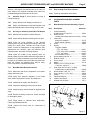
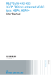
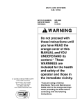
1
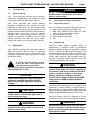
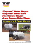
SUPER COMET
PRESSURE BLAST and VACUUM SYSTEM
O. M. 23437
MC FILE NUMBER: 2099-0300
DATE OF ISSUE:
02/20/02
REVISION:
NOTICE TO PURCHASERS AND USERS OF OUR PRODUCTS
AND THIS INFORMATIONAL MATERIAL
The products described in this material, and the information
relating to those products, is intended for knowledgeable,
experienced users of abrasive blasting equipment.
No representation is intended or made as to the suitability of the
products described herein for any particular purpose of
application. No representations are intended or made as to the
efficiency, production rate, or the useful life of the products
described herein. Any estimate regarding production rates or
production finishes are the responsibility of the user and must be
derived solely from the user’s experience and expertise, and must
not be based on information in this material.
The products described in this material may be combined by the
user in a variety of ways for purposes determined solely by the
user. No representations are intended or made as to the suitability
or engineering balance of the combination of products determined
by the user in his selection, nor as to the compliance with
regulations or standard practice of such combinations of
components or products.
© 2004 CLEMCO INDUSTRIES CORP.
One Cable Car Dr.
Washington, MO 63090
Phone (636) 239-4300
FAX (800) 726-7559
Email: [email protected]
www.clemcoindustries.com
It is the responsibility of the knowledgeable, experienced users of
the products mentioned in this material to familiarize themselves
with the appropriate laws, regulations and safe practices that
apply to these products, equipment that is connected to these
products, and materials that may be used with these products.
It is the responsibility of the user to insure that proper training of
operators has been performed and a safe work environment is
provided.
Our company is proud to provide a variety of products to the
abrasive blasting industry, and we have confidence that the
professionals in our industry will utilize their knowledge and
expertise in the safe efficient use of these products.
®
SUPER COMET PRESSURE BLAST and RECOVERY MACHINE
1.0
1.1
INTRODUCTION
Scope of manual
1.1.1 These instructions cover the set-up, operation,
maintenance, troubleshooting, and replacement parts
for the Super-Comet blast and recovery machine.
1.1.2 These instructions also contain important
information required for safe operation. All blast
operator(s) must be trained in the safe operation of the
blast machine system and all blasting accessories. The
operators and all personnel associated with the abrasive
blasting process must know about the hazards
associated with abrasive blasting. Before using the
machine, all personnel associated with the blast
machine operation must read this entire manual,
including the orange cover, and all accessory manuals.
DANGER
Danger indicates an imminently hazardous
situation which, if not avoided, will result in
death or serious injury.
1.3
Components and Theory of Operation
1.3.1
Components, Figure 1
1.3.1.1 The primary components of the Super-Comet are:
1. Blast machine with controls and blast hose
2. Blast head assembly with brushes for inside
corner, outside corner and flat surfaces.
3. Reclaimer and recovery hose
4. Dust collector and exhauster
5. Cart
1.3.2
1.2
Safety Alerts
1.2.1 Clemco uses safety alert signal words, based on
ANSI Z535.4-1998, to alert the user of a potentially
hazardous situation that may be encountered while
operating this equipment. ANSI's definitions of the signal
words are as follows:
This is the safety alert symbol. It is used
to alert the user of this equipment of
potential personal injury hazards.
Obey all safety messages that follow this symbol to
avoid possible injury or death.
CAUTION
Caution used without the safety alert symbol
indicates a potentially hazardous situation
which, if not avoided, may result in property
damage.
CAUTION
Caution indicates a potentially hazardous
situation which, if not avoided, may result in
minor or moderate injury.
WARNING
Warning indicates a potentially hazardous
situation which, if not avoided, could result in
death or serious injury.
Page 1
Blast Machine
1.3.2.1 The blast machine pressure vessel is
manufactured to American Society of Mechanical
Engineers (ASME) standards, as described in Section
VII, Div. 1, and carry a National Board certification. It is
the owners responsibility to maintain the integrity of the
vessel as may be required by some states. This may
include regular inspection and hydrostatic testing as
described in National Board Inspection Code and
Jurisdictional Regulations and /or Laws.
WARNING
Welding, grinding, or drilling on the blast
machine could weaken the vessel. Compressed
air pressure could cause a weakened vessel to
rupture, resulting in death or serious injury.
Welding, grinding, or drilling on the blast
machine vessel, without a National Board ″R″
stamp voids the ASME and National Board
certification.
1.3.2.2 All welding repairs done on the vessel must be
performed by certified welders, at shops holding a
National Board ″R″ Stamp. Welding performed by any
welder not properly qualified per the ASME Code voids
ASME and National Board certification of the vessel.
1.3.2.3 The vessel is rated for a maximum of 125 psi
(pounds per square inch); do not exceed rated pressure.
WARNING
Excessive air pressure could cause the blast
machine to rupture. To prevent serious injury or
death, do not exceed the rated pressure of the
blast machine vessel.
SUPER COMET PRESSURE BLAST and RECOVERY MACHINE
Control Cord
To blast head
Page 2
Exhauster
Reclaimer
Blast Machine
115 Volt Plug
Air Filter
Media Metering Valve
Compressed Air Inlet
Dust Collector
Exhauster
On-Off Switch
Tube Filters
Choke Valve
Debris Screen
Finger (blast) Switch
Blast Head Assembly
Dust Door
Dust Drawer
Vacuum Recovery Hose
Exhaust Muffler
Blast Hose
Figure 1
1.3.2.4 OSHA does not require pressure relief valves on
blast machines when air compressors supplying air to
the blast machines are built to ASME(1) specifications
and comply with OSHA(2) regulations. ASME Manual
section VIII, Division 1, UG-125, paragraph A90 (g)
states that pressure relief valves or protective devices
"...need not be installed directly on a pressure vessel
when the source of pressure is external to the vessel
and is under such positive control that the pressure
in the vessel cannot exceed the maximum allowable
working pressure at the operating temperature...".
OSHA regulation 1910.169 refers to the above ASME
code when describing the necessity of pressure relief
valves on compressed air equipment. DO NOT operate
blast machines with air compressors that are not
equipped with properly functioning pressure relief valves.
(1)
American Society of Mechanical Engineers, Boiler and Pressure
Vessel Code, 1989
(2)
Occupational Safety and Health Administration, 29 CFR 1910,
Subpart M - Compressed Gas and Compressed Air Equipment.
1.3.3
Theory of Operation
1.3.3.1 When the air supply is on, and electrical power
is connected, the blast machine is ready for actuation by
the switch mounted on the blast hose hand grip
assembly. Pressing the finger switch activate the
electrical solenoid, which pneumatically opens the
normally closed main inlet regulator, and closes the
normally open outlet valve. The incoming air pressurizes
the blast machine, and blasting begins. When pressure
on the switch is released, the blast machine
depressurizes, and blasting stops.
SUPER COMET PRESSURE BLAST and RECOVERY MACHINE
1.3.3.2 During operation the abrasive metering valve,
installed at the bottom of the pressure vessel, meters a
controlled quantity of abrasive into the air stream, The air
and abrasive travels through the blast hose to the blast
gun. Blasting is contained entirely within the hand held
gun assembly. A brush at the end of the assembly,
confines the abrasive and draws in atmospheric air,
sweeping the blast area clean.
1.3.3.3 Spent abrasive and by-products are conveyed
from the blast surface to the reclaimer. At the reclaimer,
the reusable abrasive material drops out of suspension
due to the cyclonic action, passes through a screen and
collects in a hopper located above the blast machine.
1.3.3.4 Air, dust and fine by-products leave the
reclaimer and are drawn through the dust collector. Dust
collects in the cloth filter, and the cleaned air passes
through the exhaust fan and is discharged into the
atmosphere. Dust particles trapped by the filter bags are
removed by a mechanical bag shaking mechanism; dust
released from the bags collects in a pan for disposal.
1.3.3.5 When the operator releases the control switch,
stopping the blast action, the blast machine
depressurizes, and automatically refills with abrasive
collected in the reclaimer hopper.
1.4
Nozzle Options
1.4.1 Super-Comets are shipped with a 3/16" orifice
tungsten carbide nozzle. Use an optional boron carbide
nozzle (and tube insert) when blasting with aggressive
abrasive. See Section 8.1.
1.5
Abrasive
1.5.1 Super-Comets are designed to utilize most
common recyclable abrasives, between 60 and 280
mesh that are specifically manufactured for blasting.
Suitable abrasive mesh sizes are based on typical
abrasive flow.
1.5.2 Glass Bead: Glass bead No. 6 to 13 may be
used. Most beads are treated to ensure free-flow
operation even with moderately high humidity. Glass
beads subjected to moisture may be reused only after
thorough drying and breaking up of the lumps.
1.5.3 Aluminum Oxide, Silicon Carbide, and
Garnet: Aggressive abrasives such as these may be
used, but consideration must be given to the rapid wear
on all parts of the system (reclaimer, nozzle, or hoses
etc.) which come in contact with the abrasive. Optional
boron nozzles are required when any of these abrasives
are used. See Section 8.1.
Page 3
1.5.4 Steel: Steel grit or shot is too heavy for the
system to recover. Do not use metallic abrasive.
1.5.5 Sand and Slag: Sand should never be used
because of the respiratory hazards associated with
abrasives containing free silica. Slags are not
recommended because they rapidly break down.
2.0
SET-UP
2.1
Compressed Air Requirements
2.1.1 Minimum air supply requirements are 70 cfm (45
cfm when nozzle is new, 70 cfm when nozzle is worn) at
80 psi.
2.1.2 The air supply line from the compressor to the
blast machine inlet should have a minimum ID of 3/4″.
2.1.3 Install an air supply hose fitting to air filter, that is
compatible with the compressed-air supply hose.
2.1.4 Install an isolation valve at the air source to
enable depressurization for service, and connect an air
line from the air source to the air filter inlet located at the
blast machine inlet.
WARNING
If twist-on type air hose couplings are used,
they must be secured by safety lock pins or
wires to prevent accidental disconnection while
under pressure. Hose disconnection while
under pressure could cause serious injury.
2.1.5 The air filter removes condensed water from the
compressed air. Its use is especially important in areas
of high humidity, or when fine-mesh abrasive is used.
Moisture causes abrasive to clot and inhibits free flow. If
moisture problems persist, an air dryer may be required.
2.2
Electrical Requirements
2.2.1 115-VAC, 1-Ph, 60-Hz, with 15 Amps. A power
cord is supplied. No additional wiring is required. SEE
FOLLOWING IMPORTANT WARNING.
WARNING
Do not use electrical adaptors that eliminate the
ground prong on 115 volt plugs. Doing so can
cause electric shock and equipment damage.
SUPER COMET PRESSURE BLAST and RECOVERY MACHINE
3.0
OPERATION
3.1
Inspection
3.3.3 Point the nozzle into a drum or suitable
container, or in the direction the abrasive is to be
disposed.
3.1.1 Make sure the coupling gaskets are in place and
in good condition before connecting the blast hose to the
quick coupling on the blast machine. Use safety lockpins or safety wire to lock the couplings together, to
prevent accidental separation during blasting.
3.1.2 Make sure that all compressed-air supply hose
connections are secured with safety lock pins and safety
cables to prevent accidental separation or disconnection.
Lock pins and safety cables are listed in Section 8.5.
WARNING
Hose disconnection while under pressure could
cause serious injury or death. Use safety lockpins and safety cables on all coupling
connections to help prevent hose couplings
from accidental disconnection.
3.1.3 Make sure that all air fittings are secure. Leaks
will cause the system to malfunction.
3.1.4 Check that the choke valve is open (handle in-line
with the piping).
3.1.5 Close the abrasive metering valve. The closed
position for the Sentinel valve is fully right.
3.2
Page 4
Loading the Machine with Abrasive
3.3.4 Hold the hose securely and pressurize the
machine by activating the control switch. Be prepared for
surging, or recoil of the hose, which can be severe.
3.3.5 When the machine is empty, release the control
switch, open the choke valve, and reset the abrasive
metering valve.
3.4
Select Brush
3.4.1 Three containment brushes are supplied: One
for flat surfaces, one for inside corners, and one for
outside corners.
3.4.2 Using the elastic brush retainer, attach the
appropriate brush to the blast head.
3.5
Blasting Operation
CAUTION
All parts to be blasted must be free of oil,
water, and other contaminants. If not clean,
the abrasive may contaminate the blast
surface, and may clog abrasive, resulting in
equipment malfunction.
3.2.1 Capacity: Abrasive capacity is approximately .5
cu. ft (1/2 cubic foot). The machine is full when abrasive
reaches the level of the pop-up valve. Overfilling will
result in abrasive carryover to the dust collector and
possible blockage in the conveying hose.
3.5.1 Operators must wear operator safety equipment.
A NIOSH-approved, supplied-air respirator protects
against inhalation of dust. Heavy gloves and clothing will
help prevent serious injury from the abrasive blast if the
closed brushes are accidentally lifted off the surface.
3.2.2 Abrasive Loading: With the exhauster off, pour
clean, dry abrasive into the reclaimer hopper through the
reclaimer door.
3.5.2 The machine is ready for operation when
compressed air and electrical power are supplied to the
machine, and the machine contains abrasive.
3.3
3.5.3 Adjust the pressure regulator, located on the
blast machine piping, to the required blasting pressure
per Section 4.1.
Emptying the Machine of Abrasive
3.3.1 When working in environments subject to
extreme temperature changes, or very humid conditions,
condensation may develop inside the machine.
Condensation wets abrasive and causes flow problems.
To prevent this, empty the machine of all abrasive when
shutting down for the day. This will eliminate trouble from
moist abrasive when starting a new day's blasting.
3.3.2 With the blast machine off, turn the blast
pressure down to approximately 40 psi, close the choke
valve and set the abrasive metering valve at full open.
3.5.4 Start the exhauster by flipping the toggle switch
located on the electrical panel.
3.5.5 Hold the blast head brushes against the surface
to be blasted, depress the finger switch, blasting (air only at
this time) will begin within a couple of seconds. Adjust the
abrasive flow per Section 4.2
SUPER COMET PRESSURE BLAST and RECOVERY MACHINE
3.5.6 To stop blasting, release the pressure on the
finger switch. Leave the brush against the surface for
several seconds after blasting stops, to ensure that all
abrasive is recovered from the surface.
3.6
Operating Technique
3.6.1 To achieve full abrasive and dust recovery the
brush must be in contact with the surface at all times.
3.6.2 Keep the brush flat against the surface. Keep the
blasting head perpendicular to the surface.
4.2
Page 5
Abrasive Metering
4.2.1 Abrasive flow is adjusted by the metering valve
located at the bottom of the blast machine. The valve is
closed when the handle is fully right. To adjust, close the
valve and slowly move the handle to the left to increase
abrasive flow. Allow time for the flow to stabilize before
further adjusting. The valve is fully open when the handle
is at the full left position. The correct flow rate will
depend on the type and size of abrasive and blasting
pressure, and can best be determined by experience.
Use as little abrasive as possible to do the job while
maintaining the best cleaning rate.
3.6.3 Do not apply excessive pressure that would cause
the brush to bend into the blast stream.
3.6.4 Make straight, even passes over the blast surface.
The blast pattern should barely overlap the pattern from the
previous pass.
3.6.5 When reversing direction, move the gun and brush
in a small radius, allowing the brush bristles to roll evenly.
5.0
PREVENTIVE MAINTENANCE
WARNING
3.7.3 Close the compressed-air supply valve.
Failure to wear approved respirators and eye
protection when servicing dust-laden areas of
the dust collector, and when emptying the dust
drawer, could result in serious eye irritation and
lung disease or death. Toxicity and health risk
vary with type of abrasive and dust generated
by blasting. The respirator must be approved
for the type of dust generated. Identify all
material being removed by blasting, and obtain
a material safety data sheet for the blast
abrasive.
3.7.4 Drain receiver tank, filters, and water collecting
devices, and bleed the compressed-air supply hose.
5.1
3.7
Shut-down
3.7.1 After blasting is complete, run the exhauster for
several seconds to clear the hoses.
3.7.2 When shutting down for the day, empty the
machine of abrasive per section 3.3.
Inspection
3.7.5
Shutdown the compressor.
5.1.1 To avoid unscheduled downtime, establish a
weekly inspection schedule. Inspect all parts subjected
to abrasive contact.
4.0
ADJUSTMENTS
5.1.2 Inspect the blast head assembly, nozzle, and
brushes for wear.
4.1
Blast Pressure
4.1.1 The blast pressure pilot regulator, located on the
blast machine, enables the user to adjust blasting
pressure to suit the application. The suitable pressure for
most purposes is 80 psi. Lower pressures may be used
for delicate work. In all cases, highest production can be
achieved only when pressure is carefully monitored.
4.1.2 To adjust, unlock the knob, and turn it clockwise
to increase pressure or counter-clockwise to decrease
pressure. Pressure will usually drop from closed-line
pressure when blasting is started. Once operating
pressure is set, lock the knob to maintain the setting.
5.1.3 Inspect the blast hose and recovery hose for
wear by squeezing and feeling for soft spots.
5.1.4 Inspect dust collector bag compartment for dust.
Check the dust bags for wear.
5.1.5 Inspect the reclaimer wear plate for wear.
Replace the wear plate before the rubber coating wears
through.
SUPER COMET PRESSURE BLAST and RECOVERY MACHINE
5.2
Dust Collector
5.2.1 The dust collector uses tubular filters which
collect dust on their inner surfaces. Every two to three
hours while the exhauster is on, clean the filter bags by
opening and closing each door four to six times in
succession. Hand pulls are provided on these two doors
which are located on the dust collector directly above the
dust drawer. Opening and closing the doors momentarily
compresses the filter bag, loosens dust, dropping it into
the dust drawer. During the blasting operation, the
collector doors must be closed tightly.
5.2.2 Empty the dust drawer regularly. Begin by
checking the drawer after every bag cleaning, and adjust
frequency based on usage and breakdown rate of
abrasive. Dump the contents into a suitable disposal
container.
CAUTION
Blast media is usually non-toxic, however,
some materials removed by the process may be
toxic. Check with proper authorities for disposal
regulations.
5.3
Debris Screen
5.3.1 The screen is accessible through the reclaimer
door. With the exhauster off, remove the screen and
empty it daily or when loading abrasive. Empty more
often if part blasted causes excessive debris. Do not
operate the machine without the screen in place.
5.4
Air Filter
5.4.1 The blast machine is equipped with a manual
drain air filter. Drain the filter at least once a day, and
more often if an abundance of moisture accumulates.
Moist air inhibits the flow of abrasive. If moisture
continues to be present, a dryer or aftercooler may be
required in the air supply line.
5.5
Changing Abrasive Type
5.5.1 When changing the type of abrasive, make sure
the blast machine, blast hose, recovery hose, and
reclaimer are carefully cleaned, to remove any remaining
abrasive material. If not carefully done the new abrasive
will be contaminated.
6.0
Page 6
SERVICE MAINTENANCE
WARNING
Failure to wear approved respirators and eye
protection when servicing dust-laden areas of
the dust collector, and when emptying the dust
collector could result in serious eye irritation
and lung disease or death. Toxicity and health
risk vary with type of media and dust generated
by blasting. Identify all material being removed
by blasting, and obtain a material safety data
sheet for the blast media.
6.1
Nozzle
6.1.1 Replace the nozzle when its diameter has
increased by 1/16", or sooner if pressure diminishes
noticeably, or if abrasive escapes from the brush. Make
sure the nozzle gasket is in place before screwing the
nozzle into the nozzle holder.
6.2
Filter Tube Replacement
CAUTION
•
•
•
Do not bend spring ends tight enough to
cause ends to kink.
Do not use a sharp instrument to force
spring rings into the opening. This could
damage the filter and seriously impair the
function of the dust collector.
Install one filter at a time. Check the seating
of the top and bottom spring rings, and that
tube is not twisted, before proceeding to the
next.
6.2.1 Replace damaged filters immediately. Remove
the old filters by pulling the spring rings off the bottom
and top tube plates. Working from the back to the front,
install one filter at a time. To install new filters, form the
end of the spring ringed tubular filter into a shallow "c"
shape, push the filter far enough into the hole of the top
plate to allow one spring ring to snap into place above
the tube plate and the other to snap into place below it.
See the illustration in Figure 2.
6.2.2 The tubular filters are held firmly by a spring ring
above and below the perimeter of the hole in the plate.
The other end of the filter is similarly installed in the
lower plate. The filters fit tight to prevent dust leakage.
To ensure a tight seal, some force may be required by
the installer. Check for proper seating at both ends, and
remove any twist before proceeding to the next filter.
SUPER COMET PRESSURE BLAST and RECOVERY MACHINE
6.5.3 To gain access to the pop-up valve, remove the
inspection door assembly.
One ring above tube plate
Top Tube Plate
6.5.4 Using a small pipe wrench, unscrew the pop-up
valve guide, by turning it counterclockwise. Remove the
pop-up valve and guide from the machine. Place the new
pop-up valve in the guide, and screw the valve guide
(with the pop-up valve in it) back into position inside the
machine. Tighten the guide as tight as possible without
using a wrench.
One ring below tube plate
Spring Ring
Bottom Tube Plate
Spring Ring
6.3
6.5.5 Put a new gasket on the inspection door and bolt
the door back onto the machine.
6.6
Figure 2
Brushes
6.3.1 To avoid unscheduled down-time, keep spare
brushes on-hand. Replace brushes at the first sign of
deterioration. Worn brush will cause abrasive escaping
at the blast surface.
6.4
Page 7
Pop-up Valve Seat Replacement
6.6.1 The easiest method to replace the rubber popup seat is through the reclaimer access door. If for some
reason replacement can not be made through the
reclaimer, observe the warning in Section 6.5, empty the
machine and bleed the air supply line. Remove the
inspection door assembly and work through the opening.
6.6.2 Remove the old seat by using a finger,
screwdriver, or similar object, to work the seat out of the
retainer groove.
Reclaimer Wear Plate Replacement
6.4.1 Remove the two screws holding the wear plate
in place, and remove the wear plate.
6.6.3 Push the new seat all the way through the port and
then fit it into the groove. Pull up on the seat and allow it to
"pop" into position.
6.4.2 Place the new wear plate into position, and
secure with self drilling screws.
6.4.3 Caulk between the wear plate and reclaimer
housing to prevent rapid wear in those areas.
6.5
Pop-up Valve Replacement
6.5.1 Empty the machine of media as described in
Section 3.3.
6.5.2 Depressurize the blast machine, and lock out
and tag out the compressed-air supply.
WARNING
Failure to observe the following procedure
before performing any maintenance could
cause serious injury or death from the sudden
release of compressed air.
• Depressurize the blast machine.
• Lock out and tag out the compressed-air
supply.
• Bleed the air supply line to the blast
machine.
7.0
TROUBLESHOOTING
WARNING
To avoid serious injury, observe the following
when troubleshooting.
• Turn off the air, and lock out and tag out the
air supply.
• If checking the controls requires air, always
enlist the aid of another person to:
•
Hold the nozzle securely.
•
Operate the finger switch.
• Never bypass the finger switch, or tie it in
the operating position.
7.1
Poor Vacuum Recovery, (abrasive escaping
at brushes)
7.1.1 Dirty tube filters. Clean the tube filters, and
empty dust drawer regularly.
7.1.2 Using friable abrasive that rapidly breaks down,
or using abrasive that is too fine or worn out.
SUPER COMET PRESSURE BLAST and RECOVERY MACHINE
7.1.3 Hole worn in recovery hose between blast head
and reclaimer inlet. Inspect hose for wear.
7.1.4 Reclaimer or dust collector door open. All doors
must be closed during operation.
7.1.5
Obstruction in recovery. Check for blockage.
7.1.6
Brushes worn. Inspect brushes.
7.2
Make
sure
7.4.2 A damaged or missing reclaimer screen will
allow large particles to pass and block the nozzle.
Replace or re-install as necessary.
7.5
Abrasive Bridging
7.5.1 Frequent bridging or blockage in the metering
valve can be caused by damp abrasive. Abrasive becomes
damp by blasting parts that are slightly oily, from moisture
in the compressed air line, or from absorption.
7.1.7 Nozzle worn. Check nozzle orifice, and replace
the nozzle if worn by 1/16″.
7.1.8 Exhauster not operating.
exhauster toggle switch is on.
Page 8
the
Abnormally High Abrasive Consumption
7.2.1 Door on reclaimer open, or improper fit or worn
door gasket. Air entering the reclaimer at this point will
cause abrasive to be carried into the dust collector. DO
NOT operate unless all doors are closed.
7.2.2
Abrasive may be too fine or worn-out.
7.2.3
Using friable abrasive that rapidly breaks down.
7.5.2 To avoid contaminating abrasive from the
workpiece, all parts should be clean and dry. If parts are
oily or greasy, degrease and dry them prior to blasting.
7.5.3 Moist compressed air may be due to: a faulty
compressor that overheats, or pumps oil or moisture into
the air line; too long an air line permitting moisture to
condense on the inside; high humidity. Drain the filter
regularly. If the problem persists, change abrasive more
often, or install an aftercooler or air dryer.
7.5.4 Absorption. Some abrasive tends to absorb
moisture from the air, especially fine-mesh abrasive in
high humidity areas. Empty the blast machine after use.
7.2.4 Nozzle pressure too high for the abrasive,
causing abrasive to break down.
7.5.5 A vibrator mounted either on the blast machine
leg or on a bolt on the abrasive metering valve may help
prevent bridging of fine-mesh abrasive.
7.2.5 Hole worn in reclaimer, or leak in reclaimer
seams. Check reclaimer for negative-pressure leaks.
7.6
Neither Abrasive Nor Air Comes Out The
Nozzle When The Finger Control Switch Is Pressed
7.3
7.6.1 Depressurize the blast machine, and check the
nozzle to see if it is plugged. See Section 7.4.
Reduction In Blast Cleaning Rate
7.3.1 Low abrasive level reducing abrasive flow.
Check and fill if low.
7.3.2 Incorrect metering valve adjustment. Adjust per
Section 4.2.
7.3.3 Reduced air pressure. This may be caused by a
malfunctioning regulator, a dirty filter element in air filter,
partially closed air valve, leaking air line, or other air
tools in use.
7.3.4 Blockage in nozzle. Blockage may occur as a
result of a missing debris screen.
7.3.5 Moist abrasive. Frequent bridges or blockage in
the area of the metering valve can be caused by
moisture. See Section 7.5.
7.4
7.6.2 Check that the blast machine pressurizes when
the switch is pressed. If it does not, see Section 7.11.
7.6.3 Check that the abrasive metering valve and the
choke valve are open.
7.7
Blast Machine Will Not Depressurize Or
Depressurizes Too Slowly
7.7.1 Faulty finger switch or solenoid valve. Check
voltage and continuity, by a qualified electrician.
7.7.2
Check the outlet muffler for blockage.
7.8
Heavy Abrasive Flow
7.8.1
Make sure the choke valve is open.
Plugged Nozzle
7.4.1 Depressurize the blast machine before checking
the nozzle for blockage.
7.8.2 Abrasive metering valve open too far. Adjust per
Section 4.2. If adjusting the valve does not regulate
abrasive flow, empty the machine, depressurize the
SUPER COMET PRESSURE BLAST and RECOVERY MACHINE
machine, and inspect the internal parts of the valve for
wear. Refer to the Sentinel metering valve manual for
troubleshooting and maintenance of the valve.
7.9
Abrasive Surge A small amount of surge is
normal at start-up.
7.9.1
Air Only (no abrasive) Comes Out The Nozzle
8.0
ACCESSORIES AND REPLACEMENT
PARTS
8.1
Blast Head and Control Assembly, Figure 3
Item
Description
1.
7.10.1 Make sure the machine contains abrasive.
2.
7.10.2 Check that the abrasive metering valve is open.
3.
7.10.3 Check for minor blockage in the abrasive
metering valve by fully opening the metering valve, and
closing the choke valve. Activate the finger control
switch, to blow out obstructions. If this procedure fails,
depressurize the machine, open the metering valve
inspection plate, and check for foreign objects.
4.
5.
7.10.4 Check the muffler on the solenoid valve. Air
should exhaust from the muffler when the finger switch is
released. If air does not exhaust, remove the muffler and
try again. If air exhausts now, the muffler is blocked. If air
does not exhaust, the solenoid valve may be faulty.
Have it checked by a qualified electrician.
6.
7.
8.
9.
10.
7.11
11.
Blast Machine Will Not Pressurize
7.11.1 Make sure that the air compressor is on and air
supply valves are open.
7.11.2 Check that pressure regulator is not turned
down. Minimum pressure is 40 psi. See Section 4.1.
Dust Leaking From Dust Collector
7.12.1 Check for damaged or loose filters.
Heavy abrasive flow. Adjust per Section 4.2
7.9.2 Empty, and depressurize the blast machine, and
inspect the internal parts of the metering valve for wear.
7.10
7.12
Page 9
12.
13.
14.
15.
16.
17.
Stock No.
Control assembly,
includes items 8, 9, and 10 ....................... 12383
Head, vacuum,
includes set screws and item 3 in alum. .12300
Insert, tube
aluminum, standard ............................... 12175
boron carbide, optional .......................... 12409
Collar ......................................................... 13890
Nozzle,
Tungsten carbide
CT-2, 1/8" orifice ................................. 01351
CT-3, 3/16" orifice, standard .............. 01352
CT-4, 1/4" orifice ................................. 01353
Boron carbide, CTB-3 ............................ 21091
Nozzle washer, pack of 10 ........................ 21580
Retainer, brush ......................................... 12039
Cover, switch ............................................ 11587
Switch ....................................................... 12119
Gasket, 1/8" x 2" foam, per foot
1 foot min., trim to fit .............................. 13089
Hose, blast 1/2" ID x 25 ft., coupled
includes item 12 and coupling ............... 01268
Nozzle holder, CHE, 1/2" .......................... 00577
Hose, vacuum, 1-1/2" x 20 ft. .................... 12450
Clamp ........................................................ 12750
Flat Surface Brush .................................... 11569
Inside Corner Brush .................................. 11570
Outside Corner Brush ............................... 11571
7.11.3 Inadequate air supply. See Section 2.1.
7.11.4 Inspect the diaphragm outlet valve for wear.
14
11
7.11.5 Inspect pop-up valve and seat for alignment and
wear.
6
12
4
5
3
2
7
15
7.11.6 Blocked or leaking control line. Check all fittings
for blockage or leaks.
16
9
7.11.7 Finger switch or solenoid valve malfunction.
Check by qualified electrician.
7.11.8 Inspect the check valve for obstruction or
broken flap.
17
13
1
10
14
8
Figure 3
SUPER COMET PRESSURE BLAST and RECOVERY MACHINE
8.2
Blast Machine, Figure 4
Item
Description
1.
2.
3.
4.
5.
6.
7.
8.
9.
10.
11.
12.
13.
Ball valve with handle, 1" .......................... 02396
Handle, 1" ball valve ................................. 22531
Pop-up valve ............................................. 01242
Seat, pop-up ............................................. 01245
Check valve, 1" swing .............................. 12187
Metering valve, Sentinel fine mesh .......... 21439
Inspection door assembly, 3" x 4" ............ 01267
Gasket, 3" x 4" inspection door ................ 01249
Regulator, 1/4" pilot, with gauge .............. 12050
Gauge, pressure, 1/8" cbm ...................... 01908
Solenoid, 4-way ........................................ 12197
Muffler, 1/4" bronze .................................. 03988
Valve, 1/2" diaphragm outlet .................... 02512
14.
15.
16.
17.
18.
19.
Stock No.
20
Page 10
Adaptor, 1" male NPT x 1" male flare ....... 11720
Pusher line assembly ............................... 22508
Muffler, exhaust ........................................ 05068
Regulator, 1" pilot operated with gauge ... 12052
Air filter, auto-drain ................................... 22425
Gasket, 5/16" x 1" adhesive backed,
(4 ft. required) ........................................ 00187
Fitting, elbow 1/4" NPT x 3/8" tube ........... 11685
Fitting, straight 1/4" NPT x 3/8" tube ........ 11736
Tubing, 3/8" OD poly, specify ft. required . 12478
CFP-P Coupling w/nipple 1-1/4″ NPT ...... 10806
Gasket, CQGP-3 pack of 10 ..................... 08853
Coupling, 1/2" ID hose, CQA-1/2 .............. 00599
Gasket, CQG, pkg of 10 ........................... 00850
Nozzle holder, CHE-1/2 ............................ 00577
Blast hose, 1/2" ID x 25 ft. coupled,
includes items 25 & 27 .......................... 01268
20.
21.
22.
23.
24.
25.
26.
27.
28.
22
9
20
10
22
11
21
19
12
1 21
6
13
4
18
3
7
5
17
10
2
1
14
8
6
20
22
26
15
5
23
25
28
27
24
Figure 4
SUPER COMET PRESSURE BLAST and RECOVERY MACHINE
8.3
Dust Collector, Figure 5
Item
Description
1.
2.
3.
Stock No.
Spring Latch .............................................11876
Gasket, door ............................................13481
Gasket, 5/16" x 1" adhesive backed,
(3 ft. required) .......................................00187
Dust Bag, 20” Long, 12 required .............11506
Gasket, air injector ...................................11754
Gasket, motor adaptor .............................11781
Motor ........................................................12315
4.
5.
6.
7.
8.6
Reclaimer, Figure 6
Item
Description
1.
2.
3.
4.
5.
6.
7.
8.
Page 11
Stock No.
Debris screen .......................................... 21265
Gasket, door ............................................ 11745
Gasket, reclaimer mount ......................... 11755
Hose, vacuum, 1-1/2" x 20 ft. .................. 12450
Clamp ...................................................... 12750
Gasket, 5/16" x 1" adhesive backed,
(4 ft. required) ...................................... 00187
Spring latch assembly ............................. 12263
Wear plate ............................................... 13882
3
4
5
8
4
2
5
1
1
3
2
7
6
7
6
Figure 5
Figure 6
8.4
Electrical, Refer to the schematic packed in
the electrical panel for items not listed
Item
Description
(-)
(-)
(-)
8.5
Stock No.
Transformer .............................................12172
Relay, 24 volts .........................................12047
Switch ......................................................12127
Miscellaneous
Caster, 4 inch, each ..............................................13142
Lock pins (pkg of 25) for twist-on couplings ..........11203
Safety cable, 1/2" hose .........................................15012