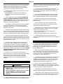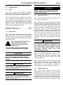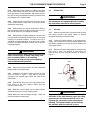
1
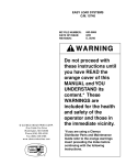
1/2" REMOTE CONTROLS
MODEL TLR-50
O.M. 03358
MC FILE NUMBER: 123-0477
DATE OF ISSUE:
04/01/77
REVISION:
H, 03-04
WARNING
© CLEMCO INDUSTRIES CORP.
One Cable Car Dr.
Washington, MO 63090
Phone (636) 239-4300
Fax (636) 239-0788
Email: [email protected]
www.clemcoindustries.com
®
Do not proceed with
these instructions until
you have READ the
preface of this
MANUAL and YOU
UNDERSTAND its
contents. These
WARNINGS are
included for the health
and safety of the
operator and those in
the immediate vicinity.
Keep this manual for
future reference
PREFACE
GENERAL INSTRUCTIONS
WARNING
•
•
•
Described herein are some, BUT NOT ALL, of the major
requirements for safe and productive use of blast
machines, remote control systems, operator respirator
assemblies, and related accessories. Completely read ALL
instruction manuals prior to using equipment.
Read and follow ALL instructions before using
this equipment.
Failure to comply with ALL instructions can result
in serious injury or death.
In the event that the user, or any assistants of the
user of this equipment cannot read or cannot
completely understand the warnings and
information contained in these instructions, the
employer of the user and his assistants must
thoroughly educate and train them on the proper
operation and safety procedures of this
equipment.
The user's work environment may include certain
HAZARDS related to the abrasive blasting operation.
Proper protection for the blaster, as well as anyone else
that may be EXPOSED to the hazards generated by the
blasting process, is the responsibility of the user and/or
the employer. Operators MUST consult with their employer
about what hazards may be present in the work
environment including, but not limited to, exposure to
dust that may contain TOXIC MATERIALS due to the
presence of silica, cyanide, arsenic or other toxins in the
abrasive, or materials present in the surface to be blasted
such as lead or heavy metals in coatings. The environment
may also include fumes that may be present from adjacent
coatings application, contaminated water, engine exhaust,
chemicals, and asbestos. The work area may include
PHYSICAL HAZARDS such as an uneven work surface,
poor visibility, excess noise, and electrical hazards. The
operator MUST consult with his employer on the
identification of potential hazards, and the appropriate
measures that MUST be taken to protect the blaster and
others that might be exposed to these hazards.
NOTICE TO PURCHASERS AND USERS OF OUR
PRODUCTS AND THIS INFORMATIONAL MATERIAL
The products described in this material, and the information
relating to those products, is intended for knowledgeable,
experienced users of abrasive blasting equipment.
No representation is intended or made as to the suitability of
the products described herein for any particular purpose or
application. No representations are intended or made as to the
efficiency, production rate, or the useful life of the products
described herein. Any estimate regarding production rates or
production finishes are the responsibility of the user and must
be derived solely from the user’s experience and expertise, and
must not be based on information in this material.
ALL machines, components and accessories MUST be
installed, tested, operated and maintained only by trained,
knowledgeable, experienced users.
The products described in this material may be combined by
the user in a variety of ways for purposes determined solely by
the user. No representations are intended or made as to the
suitability or engineering balance of the combination of
products determined by the user in his selection, nor as to the
compliance with regulations or standard practice of such
combinations of components or products.
DO NOT modify or substitute any Clemco parts with other
types or brands of equipment. Unauthorized modification
and parts substitution on supplied air respirators is a
violation of OSHA regulations and voids the NIOSH
approval.
Abrasive Blast Equipment is only a component of the range of
equipment used in an abrasive blasting job. Other products
may include an air compressor, abrasive, scaffolding, hydraulic
work platforms or booms, paint spray equipment,
dehumidification equipment, air filters and receivers, lights,
ventilation equipment, parts handling equipment, specialized
respirators, or equipment that while offered by Clemco may
have been supplied by others. Each manufacturer and supplier
of the other products used in the abrasive blasting job must be
contacted for information, training, instruction and warnings
with regard to the proper and safe use of their equipment in the
particular application for which the equipment is being used.
The information provided by Clemco is intended to provide
instruction only on Clemco products. All operators must be
trained in the proper, safe, use of this equipment. It is the
responsibility of the users to familiarize themselves with, and
comply with, all appropriate laws, regulations, and safe
practices that apply to the use of these products. Consult with
your employer about training programs and materials that are
available.
OPERATIONAL INSTRUCTIONS
OPERATOR SAFETY EQUIPMENT
WARNING
•
•
•
Our company is proud to provide a variety of products to the
abrasive blasting industry, and we have confidence that the
professionals in our industry will utilize their knowledge and
expertise in the safe efficient use of these products.
Blast operators and others working in the vicinity of
abrasive blasting must always wear properlymaintained, NIOSH-approved, respiratory protection
appropriate for the job site hazards.
DO NOT USE abrasives containing more than one
percent crystalline (free) silica. Ref. NIOSH Alert
#92-102
Inhalation of toxic dust (crystalline silica, asbestos,
lead paint and other toxins) can lead to serious or
fatal disease (silicosis, asbestosis, lead or other
poisoning).
•
ALWAYS wear NIOSH-approved supplied-air respirators
as required by OSHA, in the presence of any dust including,
but not limited to, handling or loading abrasive; blasting or
I
PREFACE
working in the vicinity of blast jobs; and cleanup of expended
abrasive. Prior to removing respirator, an air monitoring
instrument should be used to determine when surrounding
atmosphere is clear of dust and safe to breathe.
equipment. If controls are altered, involuntary activation, which
may cause serious injury, can occur.
•
Inspect the air control orifice DAILY for cleanliness.
NEVER use welding hose in place of twinline control hose. The
internal diameter and rubber composition are UNSAFE for
remote control use.
•
NIOSH-approved, supplied-air respirators are to be worn
ONLY in atmospheres:
• NOT IMMEDIATELY dangerous to life or health and,
• from which a user can escape WITHOUT using the
respirator.
•
UNLESS OTHERWISE SPECIFIED, maximum working
pressure of blast machines and related components MUST
NOT exceed National Board approved 125 psig (8.5 BAR).
•
Clemco supplied-air respirators DO NOT REMOVE OR
PROTECT AGAINST CARBON MONOXIDE (CO) OR ANY
OTHER TOXIC GAS. Carbon monoxide and toxic gas removal
and/or monitoring device must be used in conjunction with
respirator to insure safe breathing air.
•
NEVER weld on blast machine. Welding may affect
dimensional integrity of steel wall and WILL VOID National
Board approval.
•
Point nozzle ONLY at structure being blasted. High
velocity abrasive particles WILL inflict serious injury. Keep
unprotected workers OUT of blast area.
•
Air supplied to respirator MUST BE AT LEAST GRADE D
QUALITY as described in Compressed Gas Association
Commodity Specification G-7.1, and as specified by OSHA
Regulation 1910.139 (d).
•
NEVER attempt to manually move blast machine when it
contains abrasive. EMPTY machines, up to 6 cu. ft.(270kg)
capacity, are designed to be moved:
• on flat, smooth surfaces by AT LEAST two people;
• with the Clemco "Mule"; or
• with other specially designed machine moving devices.
•
ALWAYS locate compressors to prevent contaminated air
(such as CO from engine exhaust) from entering the air intake
system. A suitable in-line air purifying sorbent bed and filter or
CO Monitor should be installed to assure breathing air quality.
•
ALWAYS use a NIOSH-approved breathing air hose to
connect an appropriate air filter to the respirator. Use of a nonapproved air hose can subject the operator to illness caused by
the release of chemical agents used in the manufacture of nonapproved breathing air hose.
•
Larger empty blast machines or ANY blast machine
containing abrasive MUST be transported by mechanical lifting
equipment.
AIR HOSE, BLAST HOSE, COUPLINGS, AND NOZZLE HOLDERS
•
ALWAYS check to make sure air filter and respirator
system hoses are NOT CONNECTED to in-plant lines that
contain nitrogen, acetylene or any other non-breathable gas.
NEVER use oxygen with air line respirators. NEVER modify air
line connections to accommodate air filter/respirator breathing
hose WITHOUT FIRST testing content of the air line. FAILURE
TO TEST THE AIR LINE MAY RESULT IN DEATH TO THE
RESPIRATOR USER.
•
Air hose, air hose fittings and connectors at compressors
and blast machines MUST be FOUR times the size of the
nozzle orifice. Air hose lengths MUST be kept as short as
possible AND in a straight line. Inspect DAILY and repair
leakage IMMEDIATELY.
•
Blast hose inside diameter MUST be THREE to FOUR
times the size of the nozzle orifice. AVOID sharp bends that
wear out hose rapidly. Use SHORTEST hose lengths possible
to reduce pressure loss. Check blast hose DAILY for soft
spots. Repair or replace IMMEDIATELY.
•
Respirator lenses are designed to protect against
rebounding abrasive. They do not protect against flying objects,
glare, liquids, radiation or high speed heavy materials.
Substitute lenses from sources other than the original
respirator manufacturer will void NIOSH-approval of this
respirator.
•
ALWAYS cut loose hose ends square when installing hose
couplings and nozzle holders to allow uniform fit of hose to
coupling shoulder. NEVER install couplings or nozzle holders
that DO NOT provide a TIGHT fit on hose. ALWAYS use
manufacturers recommended coupling screws.
BLAST MACHINES AND REMOTE CONTROLS
•
Replace coupling gaskets FREQUENTLY to prevent
leakage. Abrasive leakage can result in dangerous coupling
failure. ALL gaskets MUST be checked SEVERAL times during
a working day for wear, distortion and softness.
WARNING
•
•
ALWAYS equip abrasive blast machines with
remote controls.
Abrasive blast machine operators must wear NIOSHapproved supplied-air respirators (ref: OSHA
regulations 1910.94, 1910.132, 1910.139 and
1910.244).
•
Install safety pins at EVERY coupling connection to
prevent accidental disengagement during hose movement.
•
ALWAYS attach safety cables at ALL air hose AND blast
hose coupling connections. Cables relieve tension on hose and
control whipping action in the event of a coupling blow-out.
•
NEVER modify OR substitute remote control parts. Parts
from different manufacturers are NOT compatible with Clemco
II
PREFACE
of defective parts or, at seller’s option, refund of the purchase
price, as set forth below:
1. Seller makes no warranty with respect to products used
other than in accordance hereunder.
2. On products seller manufactures, seller warrants that all
products are to be free from defects in workmanship and
materials for a period of one year from date of shipment to
buyer, but no warranty is made that the products are fit for a
particular purpose.
3. On products which seller buys and resells pursuant to this
order, seller warrants that the products shall carry the then
standard warranties of the manufacturers thereof, a copy of
which shall be made available to customer upon request.
4. The use of any sample or model in connection with this order
is for illustrative purposes only and is not to be construed as a
warranty that the product will conform to the sample or model.
5. Seller makes no warranty that the products are delivered
free of the rightful claim of any third party by way of patent
infringement or the like.
6. This warranty is conditioned upon seller’s receipt within ten
(10) days after a buyer’s discovery of a defect, of a written
notice stating in what specific material respects the product
failed to meet this warranty. If such notice is timely given, seller
will, at its option, either modify the product or part to correct the
defect, replace the product or part with complying products or
parts, or refund the amount paid for the defective product, any
one of which will constitute the sole liability of seller and a full
settlement of all claims. No allowance will be made for
alterations or repairs made by other than those authorized by
seller without the prior written consent of seller. Buyer shall
afford seller prompt and reasonable opportunity to inspect the
products for which any claim is made as above stated.
MAINTENANCE
•
ALWAYS shut off compressor and depressurize blast
machine BEFORE doing ANY maintenance.
•
Always check and clean ALL filters, screens and alarm
systems when doing any maintenance.
•
ALWAYS cage springs BEFORE disassembling valves IF
spring-loaded abrasive control valves are used.
•
ALWAYS completely follow owner's manual instructions
and maintain equipment at RECOMMENDED intervals.
ADDITIONAL ASSISTANCE
•
Training and Educational Programs.
Clemco Industries Corp. offers a booklet, Blast-Off 2,
developed to educate personnel on abrasive blast equipment
function and surface preparation techniques. Readers will learn
safe and productive use of machines, components and various
accessories, including selection of abrasive materials for
specific surface profiles and degrees of cleanliness.
•
The Society for Protective Coatings (SSPC) offers a video
training series on protective coatings including one entitled
"Surface Preparation." For loan or purchase information,
contact SSPC at the address shown below.
TECHNICAL DATA AND RESEARCH COMMITTEES
•
The following associations offer information, materials and
videos relating to abrasive blasting and safe operating
practices.
The Society for Protective Coatings (SSPC)
40 24th Street, Pittsburgh PA 15222-4643
Phone: (412) 281-2331 • FAX (412) 281-9992
Email: [email protected] • Website: www.sspc.org
National Association of Corrosion Engineers (NACE)
1440 South Creek Drive, Houston TX 77084
Phone: (281) 228-6200 • FAX (281) 228-6300
Email: [email protected] • Website: www.nace.org
American Society for Testing and Materials (ASTM)
100 Barr Harbor Dr., West Conshohocken, PA 19428
Phone (610) 832-9500 • FAX (610) 832-9555
Email: [email protected] • Website: www.astm.org
Except as expressly set forth above, all warranties, express,
implied or statutory, including implied warranty of
merchantability, are hereby disclaimed.
DAILY SET-UP CHECK LIST
WARNING
•
•
•
•
NOTICE
•
This equipment is not intended to be used in an area that might
be considered a hazardous location as described in the
National Electric Code NFPA 70 1996, article 500.
•
WARRANTY
The following is in lieu of all warranties express, implied or
statutory and in no event shall seller or its agents, successors,
nominees or assignees, or either, be liable for special or
consequential damage arising out of a breach of warranty. This
warranty does not apply to any damage or defect resulting from
negligent or improper assembly or use of any item by the buyer
or its agent or from alteration or attempted repair by any person
other than an authorized agent of seller. All used, repaired,
modified or altered items are purchased “as is” and with all
faults. In no event shall seller be liable for consequential or
incidental damages. The sole and exclusive remedy of buyer
for breach of warranty by seller shall be repair or replacement
ALL piping, fittings and hoses MUST be checked
DAILY for tightness and leakage.
ALL equipment and components MUST be thoroughly
checked for wear.
ALL worn or suspicious parts MUST be replaced.
ALL blast operators MUST be properly trained to
operate equipment.
ALL blast operators MUST be properly outfitted with
abrasive resistant clothing, safety shoes, leather gloves
and ear protection.
BEFORE blasting ALWAYS use the following check list.
□
1. PROPERLY MAINTAINED AIR COMPRESSOR sized
to provide sufficient volume (cfm) for nozzle and other tools
PLUS a 50% reserve to allow for nozzle wear. Use large
compressor outlet and large air hose (4 times the nozzle orifice
size). FOLLOW MANUFACTURERS MAINTENANCE
INSTRUCTIONS.
□
2. BREATHING AIR COMPRESSOR (oil-less air pump)
capable of providing Grade D Quality air located in a dust free,
contaminant free area. If oil-lubricated air compressor is used
to supply respirator, it should have high temperature monitor
III
PREFACE
and CO monitor or both. If CO monitor is not used, air MUST
be tested FREQUENTLY to ensure proper air quality.
□
8. BLAST HOSE with ID 3 to 4 times the nozzle orifice.
Lines MUST be run AS STRAIGHT AS POSSIBLE from
machine to work area with NO sharp bends. Check DAILY for
internal wear and external damage.
□
3. Clean, properly maintained NIOSH-APPROVED
SUPPLIED-AIR RESPIRATOR. ALL components should
ALWAYS be present. NEVER operate without inner lens in
place. Thoroughly inspect ALL components DAILY for
cleanliness and wear. ANY substitution of parts voids NIOSH
approval i.e. cape, lenses, breathing hose, breathing air supply
hose, air control valve, cool air or climate control devices.
□
4. OSHA required BREATHING AIR FILTER for removal
of moisture and particulate matter from breathing air supply.
THIS DEVICE DOES NOT REMOVE OR DETECT CARBON
MONOXIDE (CO). ALWAYS USE CO MONITOR ALARM.
9. HOSE COUPLINGS, NOZZLE HOLDERS fitted
SNUGLY to hose end and installed using PROPER coupling
screws. Coupling lugs MUST be snapped FIRMLY into locking
position. Gasket MUST form positive seal with safety pins
inserted through pin holes. Check gaskets and replace if ANY
sign of wear, softness or distortion. ALWAYS install safety
cables at every connection to prevent disengagement. Check
nozzle holder for worn threads. NEVER MIX DIFFERENT
BRANDS OF COMPONENTS. Check each of these
components DAILY.
□
□
□
10. Inspect NOZZLE and GASKET DAILY for wear.
Replace nozzle when 1/16" larger than original size or if liner
appears cracked. Check nozzle threads for wear.
5. ASME CODED BLAST MACHINE sized to hold 1/2
hour abrasive supply. ALWAYS ground machine to eliminate
static electricity hazard. Examine pop up valve for alignment.
Blast machine MUST be fitted with a screen to keep out foreign
objects and a cover to prevent entry of moisture overnight.
□
11. Use abrasive that is properly sized and free of harmful
substances; such as, free silica, cyanide, arsenic or lead.
Check material data sheet for presence of toxic or harmful
substances.
□
6. AIR LINE FILTER installed AS CLOSE AS POSSIBLE
to machine inlet. Sized to match inlet piping or larger air supply
line. Clean filter DAILY. Drain OFTEN.
□
12. Test surface to be blasted for toxic substances. Take
appropriate, and NIOSH required, protective measures for
operator and bystanders which pertain to substances found on
the surface to be blasted.
□
7. REMOTE CONTROLS MUST be in PERFECT
operating condition. ONLY use APPROVED spare parts,
including twin- line hose. DAILY: test system operation and
check button bumper and spring action of lever and lever lock.
DO NOT USE WELDING HOSE.
1 Air Compressor
11. Silica-free Abrasive
2. Breathing Air Compressor
(or)
2. Ambient Air Pump
for low pressure
respirator
5. ASME Coded
Blast Machine
7. Remote
Controls
3. NIOSH
Approved
Supplied-Air
Respirator
6. Air Line
Filter
10. Appropriately
Sized Nozzle
4. CPF Air-Filter
8. Blast Hose
9. Hose Couplings and
Safety Cables
IV
TLR-50 PNEUMATIC REMOTE CONTROLS
1.0
INTRODUCTION
1.1
Scope
1.1.1 This manual covers installation, operation,
maintenance, troubleshooting, and replacement parts for
Clemco TLR-50, 1/2" NPT Remote Control System.
1.1.2 All blast operator(s) and machine (pot) tenders
must be trained in the safe operation of the remote
control system and all other equipment used. They must
know about the hazards associated with abrasive
blasting. To ensure safe blasting, before using the
machine, read the manuals for the specific blast
machine and all accessories to be used.
Blast Machine, Manual No. ................................... 04124
RLX Control Handle, Manual No. .......................... 10574
1.2
Safety Alerts
1.2.1 Clemco uses safety alert signal words, based on
ANSI Z535.4-1998, to alert the user of a potentially
hazardous situation that may be encountered while
operating this equipment. ANSI’s definitions of the signal
words are as follows:
This is the safety alert symbol. It is
used to alert the user of this
equipment of potential personal
injury hazards.
Obey all safety messages that follow this
symbol to avoid possible injury or death.
CAUTION
Caution used without the safety alert symbol
indicates a potentially hazardous situation
which, if not avoided, may result in property
damage.
CAUTION
Caution indicates a potentially hazardous
situation which, if not avoided, may result in
minor or moderate injury.
WARNING
Warning indicates a potentially hazardous
situation which, if not avoided, could result in
death or serious injury.
Page 1
DANGER
Danger indicates an imminently hazardous
situation which, if not avoided, will result in
death or serious injury.
1.3
General Description
1.3.1 Clemco installs TLR-50 remote controls on 0.5
and 1.0 cu ft. blast machines.
OSHA requires remote controls on all blast
machines when an operator controls the nozzle.
1.3.2
The control handle, located near the blast nozzle, is the
activator for the remote control valves. When the
operator intentionally or unintentionally removes handheld pressure from the remote control handle, the
machine deactivates, stopping air and abrasive flow
through the nozzle. The remote control system “fails to
safe”, which means any interruption in the control-air
circuit for reasons such as a break in the line, the
compressor stops running, or the operator drops the
blast hose, the remote controls deactivate the blast
machine.
WARNING
Never modify or substitute remote control
parts. Parts from different manufacturers are
not compatible with Clemco equipment. If ANY
part of the remote control system is altered,
involuntary activation, which may cause
serious injury, can occur.
1.3.3 The components are shown in Figure 1. They
include the inlet valve, diaphragm outlet valve, RLX
control handle, 25-ft. and 3-ft. long twinline control
hoses, 2 control hose unions, and an 18-in. long
interconnecting hose.
1.3.4 TLR-50 Remote Controls are pressure-release
style systems which control the pressurization and
depressurization of the blast machine. Pressurization
occurs when the control handle is pressed and
depressurization occurs when the handle is released.
1.4
Operating Principles
1.4.1 Clemco Recova Remote Controls operate
pneumatically on return air (See Figure 1). If the control
handle lever (the main activator of the system) is in the
up (no blast) position, one stream of air travels down the
outbound side of the twinline and escapes through an
opening located under the lever. The normally-closed
inlet valve remains closed, and the normally-open outlet
TLR-50 PNEUMATIC REMOTE CONTROLS
Page 2
18-Inch Hose
Diaphragm Outlet Valve
Safety Petcock
Inlet Valve
3-Foot Twinline Hose
Orifice Fitting
Twinline Hose Unions (2)
25-Foot Twinline Hose
RLX Control Handle
Figure 1
valve remains open. When the control handle lever is
pressed, the opening is sealed, and air in the outbound
line returns through the inbound line to open the inlet
valve and close the outlet valve. This action pressurizes
the blast machine and begins the blasting process.
Releasing the handle exhausts the control air, which
closes the inlet valve, and opens the outlet valve to
depressurize the blast machine and stop the blasting.
2.0
INSTALLATION
2.2.1 Remove the existing inlet valve and replace it
with the Recova Inlet Valve. The directional arrow on the
valve points toward the blast machine, indicating the
direction of air flow.
2.2.2
2.2.3 Install the diaphragm outlet valves so the 1” NPT
exhaust port faces a safe direction. NOTE: The exhaust
port usually faces down. However, an optional Clemco
exhaust muffler (See Section 7.1) may be installed in the
exhaust port with the port facing up, or exhaust piping
installed, and vented into a safe area.
2.1
Factory installation: If the remote control has
been factory installed, skip to Paragraph 2.3.
2.2
Field Installation: Refer to Figure 1.
WARNING
Failure to observe the following procedure
could cause serious injury or death from the
sudden release of compressed air.
• Empty the blast machine of abrasive.
• Depressurize the blast machine.
• Lock out and tag out the compressed air
supply.
• Bleed the air supply line to the blast
machine.
Remove the existing outlet valve.
WARNING
If a muffler is not used, the exhaust piping must
be plumbed to direct exhausting air in a
direction that ensures no persons will be
exposed to possible injury from high velocity
air and media which escape when the blast
machine is depressurized.
2.3
Blast hose and control hose connections
2.3.1 Uncoil the blast hose and lay the 25-ft. twinline
hose alongside it.
TLR-50 PNEUMATIC REMOTE CONTROLS
2.3.2 Band the control handle to the blast hose close
to the nozzle holder, using the two nylon ties provided.
Once the control is firmly attached, clip the tie ends so
they will not snag the operator's clothing or interfere with
the operation of the control handle.
2.4.3 Attach the 25-ft. twinline hose to the two fittings
on the control handle. Either side of the hose can be
attached to either fitting.
2.3.4 Working from the control handle back, band or
tape the twinline hose to the blast hose every four to six
feet, and as close to the couplings as possible.
2.3.5 Make sure the coupling gaskets are in place and
not worn before connecting the blast hose to the quick
coupling on the blast machine. To reduce the risk of
accidental coupling separation when the hose is under
pressure, use safety lock-pins or safety wire to lock the
couplings together.
WARNING
Hose disconnection while under pressure could
cause serious injury or death. Use safety lockpins and safety cables on all coupling
connections to help prevent hose couplings
from accidental disconnection.
3.0
Page 3
OPERATION
WARNING
Refer to the manuals listed in paragraph 1.1.2.
Do not operate this equipment before reading
the instruction manuals for all equipment.
3.1
Start-Up
3.1.1 Make sure that all hose connections are secured
with safety lock-pins and safety cables to prevent
accidental separation or disconnection.
3.1.2 Connect the blast machine to an adequate air
supply. The compressor should be located upwind from
the blasting operation to prevent dust from entering the
compressor intake.
3.1.3 Make sure that the safety petcock located on the
inlet valve is open. The petcock is open when the
petcock lever is in-line with the petcock, as shown if
Figure 2.
Open
2.3.6 Screw the two hose unions into the unattached
fittings of the 25-ft. twinline hose.
2.3.7 Attach the 3-ft. twinline control hose to the inlet
valve as shown in Figure 1. One side of the hose
connects to the unused upper elbow, the other to the
orifice fitting.
Closed
2.3.8 Connect the other end of the 3-ft. twinline to the
hose unions on the 25-ft. twinline. Either side can
connect to either union.
2.3.9 Band the control hoses on the blast machine
side of the unions to the quick coupling nipple.
2.3.10 Make sure that all fittings are tight. Leaks will
cause the system to malfunction.
Figure 2
WARNING
To prevent severe injury from accidental
activation of the blast machine, open the safety
petcock when the blast machine is not in use.
Opening the petcock prevents unintentional
blasting. The control handle can not activate
the machine when the petcock is open.
TLR-50 PNEUMATIC REMOTE CONTROLS
3.1.4 Check to make sure that the remote control
handle lever is in the up (no blast) position, and that the
handle lever and safety lock move freely.
WARNING
A separate manual is supplied with the remote
control handle. Do not operate the machine
before first reading the remote control handle
operating instructions.
3.1.5 Check to make sure that the handle lever will
not seal the opening on control handle, unless the safety
lever lock is pulled down.
WARNING
Malfunctioning control handles could cause
unintentional actuation of a blast machine, or
prevent a machine from deactivating upon
release. Malfunctioning control handles must
be taken out of service immediately and
repaired or replaced. Serious injury or death
can result from unintentional blasting.
WARNING
All persons except for the machine tender must
stay clear of the blast machine. The blast
operator could pressurize or depressurize the
machine at any time. The noise generated by
the sudden release of compressed air when the
machine is pressurized or depressurized, may
startle bystanders, and could vent abrasive
under pressure. Either condition could result in
injury. The machine tender must wear a suitable
respirator, plus satisfactory eye, face, and
hearing protection.
3.1.10 When the blast operator is ready, either the
operator or the machine tender stands away from the
concave filling head of the blast machine, and the
exhaust port and then closes the safety petcock. Closing
the petcock prepares the machine for remote operation,
and activation by the control handle. Air should be heard
escaping from the orifice under the control handle lever
but nowhere else. The noise from air escaping at the
control handle is an audible signal, warning that air is
supplied to the blast machine, and will activate if the
control handle is pressed.
3.2
3.1.6 Start the compressor, and bring it up to
operating temperature and pressure. Blasting pressure
is usually high than 50 pounds per square inch (psi) but
must not exceed the blast machine’s pressure rating.
3.1.7 Fill the machine with screened, clean, dry
abrasive that is manufactured specifically for abrasive
blasting.
3.1.8 Open the compressor air supply valve to
pressurize the air supply line. Listen for noise that
indicates any open lines or leaks.
3.1.9 Do not allow anyone within 10 feet of the blast
machine except machine tenders who are appropriately
fitted with proper protective equipment, because the
blast operator could pressurize and depressurize the
machine without warning.
Page 4
Blasting
WARNING
Failure to wear approved respirators could
result in serious lung disease or death.
Abrasive blasting produces harmful dust. Do
not blast without the use of a properly fitted and
maintained NIOSH-approved, type CE SuppliedAir Respirator that is approved for abrasive
blasting. Everyone in the blasting area must
wear an approved respirator.
Abrasive blasting could cause abrasive
particles around the blast machine and blast
nozzle to become airborne. The loud sounds of
air released at the blast machine and nozzle
could cause hearing damage. Anyone in the
blasting area must wear approved eye
protection and hearing protection.
3.2.1 Operators must wear appropriate protective
gear, including: abrasive-resistant clothing, leather
gloves, eye and hearing protection, and a NIOSHapproved Type CE Supplied-Air Respirator.
TLR-50 PNEUMATIC REMOTE CONTROLS
3.3
Start Blasting
3.3.1 Hold the blast hose securely and point the
nozzle only at objects intended to be blast cleaned.
3.3.2 Pull back the safety lever lock and depress the
remote control handle. Within a few seconds the pop-up
valve will automatically pop up and the blast machine
will pressurize to start blasting.
WARNING
OSHA requires the use of remote controls on all
blast machines. To comply with OSHA
regulations, the remote control handle which
starts and stops the flow of air and abrasive,
must be held down manually. Do not tie down
the control handle lever or attempt to bypass
any part of the remote control system. Doing so
will defeat the purpose of the fail-to-safe feature
of the remote control. Serious injury or death
can result from uncontrolled blasting. Ref. 29
CFR 1910.244(b).
3.4
Stop Blasting
3.4.1 To stop blasting, release the control handle. The
outlet valve will open and the blast machine will
depressurize. The pop-up valve automatically drops
when air is expelled from the machine and pressure
equalizes.
3.4.2 When the control handle lever is released, the
safety lever lock will flip up to lock the handle lever in the
up (open) position.
3.4.3 Make sure that the control handle safety lever
lock is up, and that it prevents the handle lever from
engaging.
3.4.4 Always open the safety petcock during work
breaks and before filling the blast machine. Opening the
petcock prevents unintentional blasting.
Page 5
WARNING
When approaching an idle blast machine, and
before loading the blast machine with abrasive,
always check to make sure the safety petcock
is open. This step is especially important if one
worker (a machine tender) loads the machine
with abrasive while another worker (the blast
operator) controls the blasting. The blast
operator could pressurize the machine before
the machine tender has moved away from the
machine. During pressurization abrasive could
be forced out of the top of the machine, and
cause injury.
4.0
PREVENTIVE MAINTENANCE
NOTE: These preventive maintenance instructions
pertain to the remote controls only. Read the owners
manuals for the blast machine and all blast accessories,
for inspection and maintenance schedules of that
equipment.
4.1
Daily
4.1.1 With the air off, before beginning blasting,
inspect the following:
•
Inspect the RLX Control Handle; look for the
following:
• The lever must not seal the opening on the
control unless the safety lever lock is pulled down.
• The handle lever must return to the "up"
position when released.
• The safety lever lock must return to the "up"
position when the handle lever is released.
• Both the handle lever and safety lever lock must
move freely with no drag or binding.
WARNING
Malfunctioning control handles could cause
unintentional actuation of a blast machine, or
prevent a machine from deactivating upon
release. Malfunctioning control handles must
be taken out of service immediately and
repaired or replaced. Serious injury or death
could result from unintentional blasting.
TLR-50 PNEUMATIC REMOTE CONTROLS
4.1.2
•
While blasting, inspect the following:
Check the control handle for leaks.
4.2
Weekly
4.2.1
Inspect the following while blasting.
•
4.3
Inspect all control hoses, and valves for leaks. If
leaks are found, stop blasting and repair.
Periodic Inspection
NOTE: Periodic inspection of the following items will
help avoid unscheduled down-time.
5.1
Page 6
Inlet Valve, Ref. Figure 5
5.1.1 All service on the inlet valve must be done with
the air off and the air supply locked-out and tagged-out.
5.1.2 Use snap-ring pliers to remove the top and
bottom retaining rings.
5.1.3 To remove the top cap, twist the petcock/cross
assembly while pulling up.
5.1.4 Pull down on the bottom plug to remove it. If
necessary, use pliers to grab the wrench flats to remove
it from the body. Cup the bottom opening to catch the
spring, retainer, and washer as the plug is removed.
4.3.1 The remote control system is a safety device. To
be safe and to avoid unscheduled down-time, the
internal parts of the inlet valve and outlet valve should
be inspected periodically. Inspect them for wear and
lubrication of O-rings, pistons, springs, seals, and
castings. See Service Maintenance in Section 5.
5.1.5 If the piston cannot be removed with finger or
thumb force, use a dowel or similar object inserted
through the bottom opening to push the piston assembly
out the top.
4.3.2 The control handle is the actuator of the remote
control system. Periodically clean around the springs,
handle lever, and safety lever lock to ensure that the unit
is free of abrasive and debris that could cause the
handle lever or safety lever lock to bind. See the RLX
Owners Manual for service instructions.
•
4.4
•
Lubrication
4.4.1 Once per week, while the air is off, put one or
two drops of lightweight machine oil in the inlet valve
through the safety petcock. This lubricates the piston
and O-rings in the inlet and outlet valves.
5.1.6
•
•
Clean all parts and inspect for wear as follows:
The spring is approximately 1" long. If it is rusted or
compressed, replace it.
Inspect the piston, rubber washer, washer retainer
top cap and bottom plug for damage. Replace all
damaged parts.
Look into the bottom opening in the valve body. If
the machined seat is worn, replace the body.
Inspect all O-rings. If any are damaged or flattened,
replace them.
5.1.7 Remove the lower twinline hose connection, and
remove the orifice fitting for inspection. Clean the 1/16″
orifice and reassemble the connection.
WARNING
5.0
SERVICE MAINTENANCE
WARNING
Failure to observe the following before
performing any maintenance could cause
serious injury or death from the sudden release
of compressed air.
• Depressurize the blast machine.
• Lock out and tag out the compressed air
supply.
• Bleed the air supply line to the blast
machine.
The orifice fitting must not be removed,
modified, or substituted with another fitting.
Altering the orifice fitting may cause involuntary
activation of the blast machine or some other
malfunction which could result in serious injury.
5.1.8 Lubricate all O-rings, and use the illustration in
Figure 5, to reassemble the valve in reverse order,
assembling the top end first.
5.2
Diaphragm Outlet Valve, Ref. Figure 4
5.2.1 All service on the outlet valve must be done with
the air off and the air supply locked-out and tagged-out.
TLR-50 PNEUMATIC REMOTE CONTROLS
5.2.2 Remove the cap by unscrewing the four cap
screws.
5.2.3 Remove the diaphragm and inspect it for
damage. Replace as necessary.
5.2.4 Inspect the machined seat in the body. If worn,
replace the body.
5.2.5
Reassemble in reverse order.
5.3
Control handle
5.3.1 A separate manual is provided for the control
handle. Refer to the manual to service the control
handle.
6.0
TROUBLESHOOTING
NOTE: This section applies to the remote control
system only. See the appropriate manual for
troubleshooting the blast machine, control handle,
and accessories.
WARNING
To avoid serious injury or death, observe the
following when troubleshooting the remote
controls:
• Turn off the air, and lock out and tag out the
air supply.
• When checking the controls requires air,
always enlist the aid of another person to
operate the control handle while holding the
nozzle securely and pointing it in a safe
direction.
• Never strap down the remote control handle
lever in the operating position.
Page 7
6.1.3 Check for air leaks in control hose, fittings, and
control handle. (RLX Control Handle is covered in
Owners Manual No. 10574)
6.1.4 Check for air escaping from the opening under
the control handle. If no air is escaping, the orifice on the
inlet valve (Figure 5, item 9) or the line from the orifice to
the control handle is blocked and must be cleared.
6.1.5 Open the safety petcock and depress the control
handle. Air should come from the petcock. If it doesn't,
check the following:
•
The opening on the control handle is not being
sealed off.
•
The control handle leaks air.
•
The line from the control handle to the upper fitting
on the inlet valve is blocked.
•
If a diaphragm outlet valve is used, check the
diaphragm for a rupture.
If air does rush out, the inlet valve is not functioning.
Turn off the air supply and service it per Section 5.1,
disassemble the valve, clean and lubricate it, and
replace all worn or damaged parts.
6.1.6 Close the safety petcock, and press the control
handle lever. Check that no air escapes through the vent
hole on the cylinder body of the inlet valve body. Air
escaping from this vent indicates a worn piston or O-ring
in the inlet valve. See Section 5.1.
6.1.7 With the compressor off and the blast machine
depressurized, check the nozzle for blockage.
6.2 Outlet valve won't exhaust or exhausts too
slowly.
6.2.1 Make sure that the lower fitting on inlet valve
(Figure 5, item 9) has not been replaced with a fitting
with a full flow orifice. The orifice on the 1/8" NPT end of
the fitting must be 1/16" diameter.
6.2.3 Make sure the inlet valve closes. If it does not
seal-off incoming air, the valve requires service.
6.1
No blast action when the control handle is
depressed
6.3
Pop-up valve seats for a short time and then
falls, or it "hovers" but fails to seat.
6.1.1 Make sure that the air supply is on and all
supply valves are open.
6.3.1 Insufficient air supply. Check the compressor
output, air supply hose and isolation valves.
6.1.2
6.3.2 Outlet valve diaphragm may be worn or
ruptured. Inspect it and replace worn parts.
Make sure the safety petcock is closed.
TLR-50 PNEUMATIC REMOTE CONTROLS
7.0
REPLACEMENT PARTS
7.4
7.1
Optional Accessories
Item Description
Exhaust Muffler ......................................... 05068
(-)
1.
2.
3.
4.
5.
6.
7.
8.
(-)
7.2
RLX Pneumatic Control Handle
Refer to RLX Control Handle Manual No. 10574
for RLX replacement parts.
7.3
1/2" Diaphragm Outlet Valve Figure 4
Stock No.
1/2" NPT Diaphragm outlet valve ................. 02512
Nipple, 1/2" NPT x close .............................. 01733
Diaphragm ................................................... 02511
Washer, 1/4" lock.......................................... 03117
Elbow, 1/4" NPT adaptor ............................. 02513
Cap ............................................................... 02299
Body ............................................................. 02298
Nipple, 1" NPT x 3" TOE .............................. 01841
Screw, 1/4-NC x 1" cap ................................ 03053
System Replacement Parts, Figure 3
Item Description
(-)
1.
2.
3.
4.
5.
6.
7.
8.
Page 8
Stock No.
TLR-50 remote control system .................... 02518
Outlet valve, diaphragm, 1/2" NPT .............. 02512
Inlet valve assembly, 1/2" NPT .................... 02164
RLX control handle ...................................... 10565
Hose, 25' Twinline coupled .......................... 02128
Union, Twinline hose ................................... 01944
Hose, 3' Twinline coupled ............................ 02240
Hose, 3/16" x 18" coupled ........................... 02454
Hose end, reusable ...................................... 01943
6
1
2
5
3
8
4
7
7
1
Figure 4
2
6
5
3
8
4
Figure 3
TLR-50 PNEUMATIC REMOTE CONTROLS
7.5
Inlet Valve, Figure 5
Item Description
(-)
*
1.
2.
3.
4.
5.
6.
7.
8.
9
Page 9
07814 SERVICE KIT
TLR-50 INLET VALVE
Stock No.
1/2" Inlet Valve, complete ............................ 02164
Service kit, 1/2" Inlet Valve (Fig. 5a)............. 07814
Cap .............................................................. 02175
Piston ........................................................... 02192
Body ............................................................. 02170
Plug, bottom ................................................. 02176
Elbow, 1/4" NPT adaptor ............................. 02513
Reducer, 1/4" NPT x 1/8" NPT .................... 02026
Cross, 1/4" NPT brass ................................. 02193
Petcock 1/4" NPT ......................................... 01993
Adaptor 1/8" NPT with 1/16" orifice ............. 01945
Item
1.
2.
3.
4.
5.
6.
7.
8.
9.
Qty. Description
1
1
1
1
1
1
1
1
1
Retaining ring, cap
Retainer, washer
Spring, 17/32" OD x 1" long
Retaining ring, bottom plug
O-ring, 7/8" ID x 1/8" C/S
Washer
O-ring, 3/4" ID x 3/32" C/S
O-ring, 1-1/8" ID x 1/8" C/S
O-ring, 1-3/16" ID x 1/8" C/S
8
5
7
6
5
1
*
1
9
*
*
8
*
7
2
3
9
*
6
2
*
*
3
5
*
4
*
4
Figure 5
Figure 5a