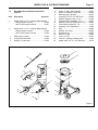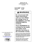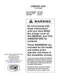
1
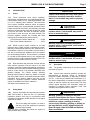
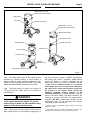
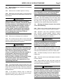
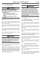
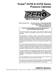
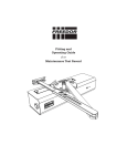
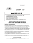
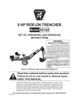
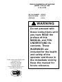
SINGLE CHAMBER BLAST MACHINE
MODEL 1028 and 1042
O. M. 04124
MC FILE NUMBER: 106/0976
DATE OF ISSUE:
01/15/77
REVISION:
I, 09/04
WARNING
© 2004 CLEMCO INDUSTRIES CORP.
One Cable Car Dr.
Washington, MO 63090
Phone (636) 239-4300
Fax (636) 239-0788
Email: [email protected]
www.clemcoindustries.com
®
Do not proceed with
these instructions until
you have READ the
preface of this
MANUAL and YOU
UNDERSTAND its
contents. These
WARNINGS are
included for the health
and safety of the
operator and those in
the immediate vicinity.
Keep this manual for
future reference.
PREFACE
GENERAL INSTRUCTIONS
WARNING
•
•
•
Described herein are some, BUT NOT ALL, of the major
requirements for safe and productive use of blast
machines, remote control systems, operator respirator
assemblies, and related accessories. Completely read ALL
instruction manuals prior to using equipment.
Read and follow ALL instructions before using
this equipment.
Failure to comply with ALL instructions can result
in serious injury or death.
In the event that the user, or any assistants of the
user of this equipment cannot read or cannot
completely understand the warnings and
information contained in these instructions, the
employer of the user and his assistants must
thoroughly educate and train them on the proper
operation and safety procedures of this
equipment.
The user's work environment may include certain
HAZARDS related to the abrasive blasting operation.
Proper protection for the blaster, as well as anyone else
that may be EXPOSED to the hazards generated by the
blasting process, is the responsibility of the user and/or
the employer. Operators MUST consult with their employer
about what hazards may be present in the work
environment including, but not limited to, exposure to
dust that may contain TOXIC MATERIALS due to the
presence of silica, cyanide, arsenic or other toxins in the
abrasive, or materials present in the surface to be blasted
such as lead or heavy metals in coatings. The environment
may also include fumes that may be present from adjacent
coatings application, contaminated water, engine exhaust,
chemicals, and asbestos. The work area may include
PHYSICAL HAZARDS such as an uneven work surface,
poor visibility, excess noise, and electrical hazards. The
operator MUST consult with his employer on the
identification of potential hazards, and the appropriate
measures that MUST be taken to protect the blaster and
others that might be exposed to these hazards.
NOTICE TO PURCHASERS AND USERS OF OUR
PRODUCTS AND THIS INFORMATIONAL MATERIAL
The products described in this material, and the information
relating to those products, is intended for knowledgeable,
experienced users of abrasive blasting equipment.
No representation is intended or made as to the suitability of
the products described herein for any particular purpose or
application. No representations are intended or made as to the
efficiency, production rate, or the useful life of the products
described herein. Any estimate regarding production rates or
production finishes are the responsibility of the user and must
be derived solely from the user’s experience and expertise, and
must not be based on information in this material.
ALL machines, components and accessories MUST be
installed, tested, operated and maintained only by trained,
knowledgeable, experienced users.
The products described in this material may be combined by
the user in a variety of ways for purposes determined solely by
the user. No representations are intended or made as to the
suitability or engineering balance of the combination of
products determined by the user in his selection, nor as to the
compliance with regulations or standard practice of such
combinations of components or products.
DO NOT modify or substitute any Clemco parts with other
types or brands of equipment. Unauthorized modification
and parts substitution on supplied air respirators is a
violation of OSHA regulations and voids the NIOSH
approval.
Abrasive Blast Equipment is only a component of the range of
equipment used in an abrasive blasting job. Other products
may include an air compressor, abrasive, scaffolding, hydraulic
work platforms or booms, paint spray equipment,
dehumidification equipment, air filters and receivers, lights,
ventilation equipment, parts handling equipment, specialized
respirators, or equipment that while offered by Clemco may
have been supplied by others. Each manufacturer and supplier
of the other products used in the abrasive blasting job must be
contacted for information, training, instruction and warnings
with regard to the proper and safe use of their equipment in the
particular application for which the equipment is being used.
The information provided by Clemco is intended to provide
instruction only on Clemco products. All operators must be
trained in the proper, safe, use of this equipment. It is the
responsibility of the users to familiarize themselves with, and
comply with, all appropriate laws, regulations, and safe
practices that apply to the use of these products. Consult with
your employer about training programs and materials that are
available.
OPERATIONAL INSTRUCTIONS
OPERATOR SAFETY EQUIPMENT
WARNING
•
•
•
Our company is proud to provide a variety of products to the
abrasive blasting industry, and we have confidence that the
professionals in our industry will utilize their knowledge and
expertise in the safe efficient use of these products.
Blast operators and others working in the vicinity of
abrasive blasting must always wear properlymaintained, NIOSH-approved, respiratory protection
appropriate for the job site hazards.
DO NOT USE abrasives containing more than one
percent crystalline (free) silica. Ref. NIOSH Alert
#92-102
Inhalation of toxic dust (crystalline silica, asbestos,
lead paint and other toxins) can lead to serious or
fatal disease (silicosis, asbestosis, lead or other
poisoning).
•
ALWAYS wear NIOSH-approved supplied-air respirators
as required by OSHA, in the presence of any dust including,
but not limited to, handling or loading abrasive; blasting or
working in the vicinity of blast jobs; and cleanup of expended
I
PREFACE
abrasive. Prior to removing respirator, an air monitoring
instrument should be used to determine when surrounding
atmosphere is clear of dust and safe to breathe.
equipment. If controls are altered, involuntary activation, which
may cause serious injury, can occur.
•
Inspect the air control orifice DAILY for cleanliness.
NEVER use welding hose in place of twinline control hose. The
internal diameter and rubber composition are UNSAFE for
remote control use.
•
NIOSH-approved, supplied-air respirators are to be worn
ONLY in atmospheres:
• NOT IMMEDIATELY dangerous to life or health and,
• from which a user can escape WITHOUT using the
respirator.
•
UNLESS OTHERWISE SPECIFIED, maximum working
pressure of blast machines and related components MUST
NOT exceed National Board approved 125 psig (8.5 BAR).
•
Clemco supplied-air respirators DO NOT REMOVE OR
PROTECT AGAINST CARBON MONOXIDE (CO) OR ANY
OTHER TOXIC GAS. Carbon monoxide and toxic gas removal
and/or monitoring device must be used in conjunction with
respirator to insure safe breathing air.
•
NEVER weld on blast machine. Welding may affect
dimensional integrity of steel wall and WILL VOID National
Board approval.
•
Air supplied to respirator MUST BE AT LEAST GRADE D
QUALITY as described in Compressed Gas Association
Commodity Specification G-7.1, and as specified by OSHA
Regulation 1910.139 (d).
•
Point nozzle ONLY at structure being blasted. High
velocity abrasive particles WILL inflict serious injury. Keep
unprotected workers OUT of blast area.
•
ALWAYS locate compressors to prevent contaminated air
(such as CO from engine exhaust) from entering the air intake
system. A suitable in-line air purifying sorbent bed and filter or
CO Monitor should be installed to assure breathing air quality.
•
NEVER attempt to manually move blast machine when it
contains abrasive. EMPTY machines, up to 6 cu. ft.(270kg)
capacity, are designed to be moved:
• on flat, smooth surfaces by AT LEAST two people;
• with the Clemco "Mule"; or
• with other specially designed machine moving devices.
•
ALWAYS use a NIOSH-approved breathing air hose to
connect an appropriate air filter to the respirator. Use of a nonapproved air hose can subject the operator to illness caused by
the release of chemical agents used in the manufacture of nonapproved breathing air hose.
•
Larger empty blast machines or ANY blast machine
containing abrasive MUST be transported by mechanical lifting
equipment.
•
ALWAYS check to make sure air filter and respirator
system hoses are NOT CONNECTED to in-plant lines that
contain nitrogen, acetylene or any other non-breathable gas.
NEVER use oxygen with air line respirators. NEVER modify air
line connections to accommodate air filter/respirator breathing
hose WITHOUT FIRST testing content of the air line. FAILURE
TO TEST THE AIR LINE MAY RESULT IN DEATH TO THE
RESPIRATOR USER.
AIR HOSE, BLAST HOSE, COUPLINGS, AND NOZZLE HOLDERS
•
Air hose, air hose fittings and connectors at compressors
and blast machines MUST be FOUR times the size of the
nozzle orifice. Air hose lengths MUST be kept as short as
possible AND in a straight line. Inspect DAILY and repair
leakage IMMEDIATELY.
•
Blast hose inside diameter MUST be THREE to FOUR
times the size of the nozzle orifice. AVOID sharp bends that
wear out hose rapidly. Use SHORTEST hose lengths possible
to reduce pressure loss. Check blast hose DAILY for soft
spots. Repair or replace IMMEDIATELY.
•
Respirator lenses are designed to protect against
rebounding abrasive. They do not protect against flying objects,
glare, liquids, radiation or high speed heavy materials.
Substitute lenses from sources other than the original
respirator manufacturer will void NIOSH-approval of this
respirator.
•
ALWAYS cut loose hose ends square when installing hose
couplings and nozzle holders to allow uniform fit of hose to
coupling shoulder. NEVER install couplings or nozzle holders
that DO NOT provide a TIGHT fit on hose. ALWAYS use
manufacturers recommended coupling screws.
BLAST MACHINES AND REMOTE CONTROLS
•
Replace coupling gaskets FREQUENTLY to prevent
leakage. Abrasive leakage can result in dangerous coupling
failure. ALL gaskets MUST be checked SEVERAL times during
a working day for wear, distortion and softness.
WARNING
•
•
ALWAYS equip abrasive blast machines with
remote controls.
Abrasive blast machine operators must wear NIOSHapproved supplied-air respirators (ref: OSHA
regulations 1910.94, 1910.132, 1910.139 and
1910.244).
•
Install safety pins at EVERY coupling connection to
prevent accidental disengagement during hose movement.
•
ALWAYS attach safety cables at ALL air hose AND blast
hose coupling connections. Cables relieve tension on hose and
control whipping action in the event of a coupling blow-out.
•
NEVER modify OR substitute remote control parts. Parts
from different manufacturers are NOT compatible with Clemco
II
PREFACE
price, as set forth below:
1. Seller makes no warranty with respect to products used
other than in accordance hereunder.
2. On products seller manufactures, seller warrants that all
products are to be free from defects in workmanship and
materials for a period of one year from date of shipment to
buyer, but no warranty is made that the products are fit for a
particular purpose.
3. On products which seller buys and resells pursuant to this
order, seller warrants that the products shall carry the then
standard warranties of the manufacturers thereof, a copy of
which shall be made available to customer upon request.
4. The use of any sample or model in connection with this order
is for illustrative purposes only and is not to be construed as a
warranty that the product will conform to the sample or model.
5. Seller makes no warranty that the products are delivered
free of the rightful claim of any third party by way of patent
infringement or the like.
6. This warranty is conditioned upon seller’s receipt within ten
(10) days after a buyer’s discovery of a defect, of a written
notice stating in what specific material respects the product
failed to meet this warranty. If such notice is timely given, seller
will, at its option, either modify the product or part to correct the
defect, replace the product or part with complying products or
parts, or refund the amount paid for the defective product, any
one of which will constitute the sole liability of seller and a full
settlement of all claims. No allowance will be made for
alterations or repairs made by other than those authorized by
seller without the prior written consent of seller. Buyer shall
afford seller prompt and reasonable opportunity to inspect the
products for which any claim is made as above stated.
MAINTENANCE
•
ALWAYS shut off compressor and depressurize blast
machine BEFORE doing ANY maintenance.
•
Always check and clean ALL filters, screens and alarm
systems when doing any maintenance.
•
ALWAYS cage springs BEFORE disassembling valves IF
spring-loaded abrasive control valves are used.
•
ALWAYS completely follow owner's manual instructions
and maintain equipment at RECOMMENDED intervals.
ADDITIONAL ASSISTANCE
•
Training and Educational Programs.
Clemco Industries Corp. offers a booklet, Blast-Off 2,
developed to educate personnel on abrasive blast equipment
function and surface preparation techniques. Readers will learn
safe and productive use of machines, components and various
accessories, including selection of abrasive materials for
specific surface profiles and degrees of cleanliness.
•
The Society for Protective Coatings (SSPC) offers a video
training series on protective coatings including one entitled
"Surface Preparation." For loan or purchase information,
contact SSPC at the address shown below.
TECHNICAL DATA AND RESEARCH COMMITTEES
•
The following associations offer information, materials and
videos relating to abrasive blasting and safe operating
practices.
The Society for Protective Coatings (SSPC)
40 24th Street, Pittsburgh PA 15222-4643
Phone: (412) 281-2331 • FAX (412) 281-9992
Email: [email protected] • Website: www.sspc.org
National Association of Corrosion Engineers (NACE)
1440 South Creek Drive, Houston TX 77084
Phone: (281) 228-6200 • FAX (281) 228-6300
Email: [email protected] • Website: www.nace.org
American Society for Testing and Materials (ASTM)
100 Barr Harbor Dr., West Conshohocken, PA 19428
Phone (610) 832-9500 • FAX (610) 832-9555
Email: [email protected] • Website: www.astm.org
Except as expressly set forth above, all warranties, express,
implied or statutory, including implied warranty of
merchantability, are hereby disclaimed.
DAILY SET-UP CHECK LIST
WARNING
•
•
•
•
NOTICE
•
This equipment is not intended to be used in an area that might
be considered a hazardous location as described in the
National Electric Code NFPA 70 1996, article 500.
•
WARRANTY
The following is in lieu of all warranties express, implied or
statutory and in no event shall seller or its agents, successors,
nominees or assignees, or either, be liable for special or
consequential damage arising out of a breach of warranty. This
warranty does not apply to any damage or defect resulting from
negligent or improper assembly or use of any item by the buyer
or its agent or from alteration or attempted repair by any person
other than an authorized agent of seller. All used, repaired,
modified or altered items are purchased “as is” and with all
faults. In no event shall seller be liable for consequential or
incidental damages. The sole and exclusive remedy of buyer
for breach of warranty by seller shall be repair or replacement
of defective parts or, at seller’s option, refund of the purchase
ALL piping, fittings and hoses MUST be checked
DAILY for tightness and leakage.
ALL equipment and components MUST be thoroughly
checked for wear.
ALL worn or suspicious parts MUST be replaced.
ALL blast operators MUST be properly trained to
operate equipment.
ALL blast operators MUST be properly outfitted with
abrasive resistant clothing, safety shoes, leather gloves
and ear protection.
BEFORE blasting ALWAYS use the following check list.
□
1. PROPERLY MAINTAINED AIR COMPRESSOR sized
to provide sufficient volume (cfm) for nozzle and other tools
PLUS a 50% reserve to allow for nozzle wear. Use large
compressor outlet and large air hose (4 times the nozzle orifice
size). FOLLOW MANUFACTURERS MAINTENANCE
INSTRUCTIONS.
□
2. BREATHING AIR COMPRESSOR (oil-less air pump)
capable of providing Grade D Quality air located in a dust free,
contaminant free area. If oil-lubricated air compressor is used
to supply respirator, it should have high temperature monitor
and CO monitor or both. If CO monitor is not used, air MUST
III
PREFACE
be tested FREQUENTLY to ensure proper air quality.
□
8. BLAST HOSE with ID 3 to 4 times the nozzle orifice.
Lines MUST be run AS STRAIGHT AS POSSIBLE from
machine to work area with NO sharp bends. Check DAILY for
internal wear and external damage.
□
3. Clean, properly maintained NIOSH-APPROVED
SUPPLIED-AIR RESPIRATOR. ALL components should
ALWAYS be present. NEVER operate without inner lens in
place. Thoroughly inspect ALL components DAILY for
cleanliness and wear. ANY substitution of parts voids NIOSH
approval i.e. cape, lenses, breathing hose, breathing air supply
hose, air control valve, cool air or climate control devices.
□
9. HOSE COUPLINGS, NOZZLE HOLDERS fitted
SNUGLY to hose end and installed using PROPER coupling
screws. Coupling lugs MUST be snapped FIRMLY into locking
position. Gasket MUST form positive seal with safety pins
inserted through pin holes. Check gaskets and replace if ANY
sign of wear, softness or distortion. ALWAYS install safety
cables at every connection to prevent disengagement. Check
nozzle holder for worn threads. NEVER MIX DIFFERENT
BRANDS OF COMPONENTS. Check each of these
components DAILY.
□
4. OSHA required BREATHING AIR FILTER for removal
of moisture and particulate matter from breathing air supply.
THIS DEVICE DOES NOT REMOVE OR DETECT CARBON
MONOXIDE (CO). ALWAYS USE CO MONITOR ALARM.
□
5. ASME CODED BLAST MACHINE sized to hold 1/2
hour abrasive supply. ALWAYS ground machine to eliminate
static electricity hazard. Examine pop up valve for alignment.
Blast machine MUST be fitted with a screen to keep out foreign
objects and a cover to prevent entry of moisture overnight.
□
10. Inspect NOZZLE and GASKET DAILY for wear.
Replace nozzle when 1/16" larger than original size or if liner
appears cracked. Check nozzle threads for wear.
□
11. Use abrasive that is properly sized and free of harmful
substances; such as, free silica, cyanide, arsenic or lead.
Check material data sheet for presence of toxic or harmful
substances.
□
6. AIR LINE FILTER installed AS CLOSE AS POSSIBLE
to machine inlet. Sized to match inlet piping or larger air supply
line. Clean filter DAILY. Drain OFTEN.
□
□
12. Test surface to be blasted for toxic substances. Take
appropriate, and NIOSH required, protective measures for
operator and bystanders which pertain to substances found on
the surface to be blasted.
7. REMOTE CONTROLS MUST be in PERFECT
operating condition. ONLY use APPROVED spare parts,
including twin- line hose. DAILY: test system operation and
check button bumper and spring action of lever and lever lock.
DO NOT USE WELDING HOSE.
1 Air Compressor
11. Silica-free Abrasive
5. ASME Coded
Blast Machine
7. Remote
Controls
2. Breathing Air Compressor
(or)
2. Ambient Air Pump
for low pressure
respirator
3. NIOSH
Approved
Supplied-Air
Respirator
6. Air Line
Filter
10. Appropriately
Sized Nozzle
4. CPF Air-Filter
8. Blast Hose
9. Hose Couplings and
Safety Cables
IV
MODEL 1028 & 1042 BLAST MACHINE
1.0
INTRODUCTION
1.1
Scope
1.1.1 These instructions cover set-up, operation,
maintenance, troubleshooting, and replacement parts for
Clemco Model 1028 (0.5 cu ft. capacity) and Model 1042
(1.0 cu ft. capacity) blast machines. The instructions
cover remote controlled machines (when an operator
controls blasting from a pneumatically operated control
handle mounted at the nozzle), and manually controlled
machines (a blast machine fitted with simple ball valves
at the inlet and outlet, that must be manually opened
and closed to start and stop the blast process) The
following separate manuals are included with blast
machine when furnished with remote controls.
TLR-50 Remote Controls, Manual No. .......... 03358
RLX Control Handle, Manual No. ................... 10574
1.1.2 OSHA requires remote controls on all blast
machines when a blast operator commands the nozzle.
Manually controlled blast machines are allowed only in
cases where a machine is connected to a fixed nozzle or
tool that is enclosed and separated from the operator
and surrounding personnel. If this machine is intended
for use with a blast operator and it is not equipped with
remotes controls, contact a Clemco distributor for a TLR50 remote control system (Stock No. 02518).
1.1.3 Blast operators and personnel involved with the
blast machine operation must be trained in the safe
operation of the blast machine and blasting accessories.
All personnel involved with the abrasive blasting process
must be made aware of the hazards associated with
abrasive blasting. The Clemco booklet ″Abrasive
Blasting Safety Practices″ Stock No. 22090, is included
with every blast machine, and contains important safety
information about abrasive blasting that may not be
included in equipment operation manuals. Additional
copies are available from Clemco Industries.
Visit www.clemcoindustries.com
1.2
Safety Alerts
1.2.1 Clemco uses safety alert signal words, based on
ANSI Z535.4-1998, to alert the user of a potentially
hazardous situation that may be encountered while
operating this equipment. ANSI's definitions of the signal
words are as follows:
This is the safety alert symbol. It is used to
alert the user of this equipment of potential
personal injury hazards.
Obey all safety messages that follow this symbol to
avoid possible injury or death.
Page 1
CAUTION
Caution used without the safety alert symbol
indicates a potentially hazardous situation
which, if not avoided, may result in property
damage.
CAUTION
Caution indicates a potentially hazardous
situation which, if not avoided, may result in
minor or moderate injury.
WARNING
Warning indicates a potentially hazardous
situation which, if not avoided, could result in
death or serious injury.
DANGER
Danger indicates an imminently hazardous
situation which, if not avoided, will result in
death or serious injury.
1.3
Description
1.3.1 The primary components of the blast machine
are shown in Figure 1.
1.3.2 Clemco blast machines (pressure vessels) are
manufactured to American Society of Mechanical
Engineers (ASME) standards, as described in Section
VII, Div. 1, and carry a National Board certification. It is
the owner’s responsibility to maintain the integrity of the
vessel as may be required by some states. This may
include regular inspection and hydrostatic testing as
described in National Board Inspection Code and
Jurisdictional Regulations and /or Laws.
WARNING
Welding, grinding, or drilling on the blast
machine could weaken the vessel. Compressed
air pressure could cause a weakened blast
machine to rupture, resulting in death or
serious injury. Welding, grinding, or drilling on
the blast machine vessel, without a National
Board R stamp voids the ASME and National
Board certification.
MODEL 1028 & 1042 BLAST MACHINE
Page 2
Model 1028 , 0.5 Cu Ft
Shown with remote controls
Outlet Valve
Inlet Valve
Air-Inlet Connection
Model 1042, 1.0 Cu Ft.
Shown with manual valves
Manual Outlet Valve
Manual Inlet Valve
Air-Inlet Connection
Optional Screen
Pop-up Valve
Choke Valve
Inspection Door
Abrasive
Metering valve
Blast-Hose Connection
Figure 1
1.3.3 All welding repairs done on the vessel must be
performed by certified welders, at shops holding a
National Board R Stamp. Welding performed by any
welder not properly qualified per the ASME Code voids
ASME and National Board certification of the vessel.
1.3.4 This blast machine is rated for a maximum of
125 psi (pounds per square inch); do not exceed the
rated pressure.
WARNING
Excessive compressed air pressure could
cause a blast machine to rupture. To prevent
serious injury or death, do not exceed the rated
pressure of the blast machine vessel.
1.3.5 OSHA does not require pressure relief valves on
blast machines when air compressors supplying air to
the blast machines are built to ASME(1) specifications
and comply with OSHA(2) regulations. ASME Manual
section VIII, Division 1, UG-125, paragraph A90 (g)
states that pressure relief valves or protective devices
"...need not be installed directly on a pressure
vessel when the source of pressure is external to
the vessel and is under such positive control that
the pressure in the vessel cannot exceed the
maximum allowable working pressure at the
operating temperature...". OSHA regulation 1910.169
refers to the above ASME code when describing the
necessity of pressure relief valves on compressed air
equipment. DO NOT operate blast machines with air
compressors that are not equipped with properly
functioning pressure relief valves.
(1)
American Society of Mechanical Engineers, Boiler and Pressure
Vessel Code, 1989
(2)
Occupational Safety and Health Administration, 29 CFR 1910,
Subpart M - Compressed Gas and Compressed Air Equipment.
MODEL 1028 & 1042 BLAST MACHINE
Page 3
Compressed Air and Abrasives Consumption
Consumption rates are based on abrasives that weigh 100 pounds per cubic foot
Nozzle
Orifice
Size (in.)
No. 2
1/8"
No. 3
3/16"
No. 4
1/4"
•
•
•
•
Pressure At The Nozzle (psi)
50
11
67
2.5
26
150
6
47
268
11
60
13
77
3
30
171
7
54
312
12
70
15
88
3.5
33
196
8
61
354
14
80
17
101
4
38
216
9
68
408
16
90
19
112
4.5
41
238
10
74
448
17
100
20
123
5
45
264
10
81
494
18
125
25
152
5.5
55
319
12
98
608
22
Air, Power
and Abrasive
Requirements
Air (cfm)
Abrasive lbs/hr)
Compressor (hp)
Air (cfm)
Abrasive (lbs/hr)
Compressor (hp)
Air (cfm)
Abrasive (lbs/hr)
Compressor (hp)
Air requirements were measured by a flow meter under actual blasting conditions, and are therefore lower than figures for air
alone, with no abrasive.
Horsepower requirements are based on 4.5 cfm per horsepower.
Figures are for reference only, and may vary for different working conditions. Several variables, including metering valve
adjustments, can affect abrasive flow.
Figures show approximate compressed air and abrasive consumption when nozzles are new. Consumption will increase as
the nozzle wears.
Figure 2
1.3.6
Compressed-air Requirements
1.3.6.1 The size of the compressor required depends on
the orifice size of the nozzle and blasting pressure.
Unless specified otherwise, blast machine packages are
supplied with a 1/4" orifice nozzle. Nozzles larger than
1/4" are not recommended because the accelerated
velocity rapidly wears the blast hose.
1.3.6.2 Refer to the table in Figure 2 to determine cfm
requirements. The table shows air consumption of
nozzles when new. It does not show the recommended
compressor size. As nozzles wear, they will consume
70% to 80% more air. Consult with a compressor
supplier for suggested compressor size based on the air
consumption of the next larger orifice size.
1.3.7
Remote Controls
1.3.7.1 Separate manuals are provided for the
operation, maintenance, and replacement parts for the
TLR-50 remote controls (Manual Stock No. 03358) and
RLX control handle (Manuals Stock No. 10574). Refer to
those manuals for set-up and operation of the remote
control system.
1.3.8
Air Filter, Optional
1.3.8.1 The optional air filter at the blast machine inlet
removes water condensed in the compressed air line. Its
use is especially important in areas of high humidity, or
when fine-mesh abrasive is used. Moisture causes
media to clot and inhibits free flow through the metering
valve. See Section 7.1 for accessories. If moisture
problems persist, an air dryer may be required.
2.0
INITIAL SET-UP
2.1
Blast Machine Set-Up
2.1.2 Install an air supply hose fitting to the inlet valve
(or filter), that is compatible with the compressed-air
supply hose. See Section 3.2.2.
2.2
Remote Control Set-Up
2.2.1 Refer to the remote control manual for set-up
and operation of the control system.
MODEL 1028 & 1042 BLAST MACHINE
3.0
OPERATION
3.1
Transporting and moving
3.1.1
Transporting a blast machine
3.1.1.1 Always empty the machine before transporting.
Transporting a machine containing abrasive may
increase the weight to an unsafe handling limit, and
could cause abrasive to settle in the piping.
WARNING
• Always empty the blast machine before
lifting or hoisting.
• Never hoist the machine by the handle or
piping, or with a sling through the handle or
piping.
• When transporting a machine on a pallet,
always securely attach the machine to a sturdy
pallet.
• Always securely anchor the machine to the
transport vehicle.
• Failure to observe these warnings could
result in serious injury or death.
3.1.2
Moving a blast machine
WARNING
Page 4
WARNING
If twist-on type air hose couplings are used,
they must be secured by safety lock pins or
wires to prevent accidental disconnection while
under pressure. Hose disconnection while
under pressure could cause serious injury.
3.2.3 Make sure the coupling gaskets are in place and
in good condition before connecting the blast hose to the
quick coupling on the blast machine. To prevent
accidental separation during blasting, use safety lockpins or safety wire to lock the couplings together.
3.2.4 Make sure that all hose connections are secure.
Install safety lock pins on all quick coupling. Use lock
pins and safety cables on all quick coupling connections
to help prevent accidental separation of hoses. Lock
pins and safety cables are listed in Section 7.3.
WARNING
Hose disconnection while under pressure could
cause serious injury or death. Use safety lockpins and safety cables on all coupling
connections to help prevent hose couplings
from accidental disconnection.
3.2.5 Make sure the choke valve is open (handle inline with the piping).
Never manually move a blast machine when it
contains abrasive. Empty (model 1028 and
1042) machines may be moved when the
following criteria are met.
3.2.6 Close the abrasive metering valve. The closed
position is when the handle is pointing toward the pipe
nipples in the metering valve.
3.1.2.1 An empty machine may be moved manually, on
level flat surfaces.
3.2.7 Close the air valve on the compressor. Start the
compressor, and bring it up to operating temperature
and pressure. The pressure must not exceed 125 psi.
3.1.2.2 Move the machine by pushing it in a forward
direction. Do not back-up while moving the machine, as
potential tripping hazards cannot be seen.
3.2.8 Load abrasive into the machine by following the
instructions in Section 3.6.
3.2
3.2.9 If the machine is equipped with manual valves,
make sure the inlet valve is closed (handle
perpendicular to the valve).
Set-up
3.2.1 Locate the compressor upwind and/or away
from the blasting operation to prevent contaminated air
from entering the compressor intake.
3.2.2 Connect a 3/4" ID or larger air line from the
compressor to the air supply hose connector previously
installed on the blast machine inlet.
NOTE: If the air line supplies air to other pneumatic
tools, install isolation valves to enable depressurization
of each line for service.
3.2.10 If the machine is equipped with remote controls,
make sure the control handle is in the “up” (no blast)
position.
3.2.11 Slowly open the compressor air valve to
pressurize the air supply line. Listen for noise that
indicates any open lines or leaks.
MODEL 1028 & 1042 BLAST MACHINE
3.3
Manual Blasting. See Section 3.4 for blasting
with remote controls.
3.3.1
Make sure the ventilation system is running.
3.3.2 Make sure the nozzle fixture is secure and that
the nozzle is directed only toward objects intended to be
blast cleaned.
WARNING
OSHA requires remote controls on all blast
machines when an operator controls the nozzle.
If a blast operator is controlling the nozzle of a
manually controlled blast machine, contact a
Clemco distributor for a compatible remote
control system. Ignoring this warning places
the operator at risk of severe injury or death
from accidents that could occur from an
uncontrolled blast nozzle.
3.3.3
Make sure the blasting area is contained.
3.3.4 Do not allow anyone within 10 feet of the blast
machine except machine tenders, who are appropriately
fitted with approved protective equipment.
WARNING
All persons except for the machine tender must
stay clear of the blast machine. The tender may
pressurize or depressurize the machine at any
time. The noise generated by the sudden
release of compressed air when the machine is
pressurized or depressurized, may startle
bystanders, and may vent abrasive under
pressure. Either condition could result in injury.
The machine tender must wear a suitable,
approved respirator, plus approved eye, face,
and hearing protection.
3.3.5 The machine tender closes the outlet valve, and
while standing back and facing away from the concave
filling head, opens the inlet valve. This action causes the
pop-up valve to seal off the filling port and pressurizes
the blast machine.
3.3.6 If the abrasive metering valve is closed as
instructed in Section 3.2.6, only air will exit the nozzle.
Adjust the metering valve per Section 3.5.
Page 5
WARNING
Never leave a pressurized machine unattended.
If an emergency occurs, such as a burst blast
hose, shut-down the machine immediately.
3.3.7 To stop blasting, the machine tender closes the
inlet valve, and while standing back and facing away
from the concave head and outlet valve, quickly opens
the outlet valve. The pop-up valve drops when air is
expelled from the machine and pressure equalizes.
3.4
Blasting with Remote Controls. See Section
3.3 for manual blasting.
3.4.1 Refer to the remote control manual to ensure
the machine is correctly set-up and ready for blasting.
3.4.2 Operators must wear appropriate protective
gear, including: abrasive-resistant clothing, leather
gloves, hearing protection, and a NIOSH-approved, and
properly maintained supplied-air respirator.
WARNING
Abrasive blasting produces harmful dust.
Everyone in the blasting area must wear a
properly fitted and properly maintained
NIOSH-approved supplied-air respirator.
3.4.3 Close the safety petcock located on the inlet
valve. Air should now be heard escaping from the orifice
under the control handle lever, but from no other place.
3.4.4 Pull back the safety lever lock under the control
handle lever.
3.4.5 Point the nozzle only toward objects intended to
be blast cleaned.
3.4.6 While holding the lever lock down, press the
control handle lever. Be prepared; blasting will begin as
soon as the machine pressurizes.
WARNING
OSHA requires remote controls on all blast
machines when an operator controls the nozzle.
Do not tie down the control handle or attempt to
bypass any part of the remote control system.
Doing so will defeat the purpose of the fail-tosafe feature of the remote control. Severe injury
or death can result from uncontrolled blasting.
MODEL 1028 & 1042 BLAST MACHINE
3.4.7 If the abrasive metering valve is closed as
instructed, in Section 3.2.6, only air will exit the nozzle.
Adjust the metering valve per Section 3.5.
3.6.3 After the machine
procedures to begin blasting.
3.7
3.4.8 To stop blasting, release the control handle
lever. The safety lever lock automatically pops up to
prevent accidental activation of the blast machine.
3.4.9 Open the safety petcock. Always open the
safety petcock during work breaks to prevent
unintentional blasting.
3.5
Adjust Abrasive Metering Valve
3.5.1 Abrasive flow is adjusted with the metering
handle. Begin adjustments with the metering valve
closed. Closed is when the handle is turned fully
clockwise when viewed from the top.
3.5.2 Increase abrasive flow by moving the handle
counterclockwise, at 1/8” or increments or less, allowing
time for the flow to stabilize before readjusting.
3.5.3 Optimum abrasive flow depends on the type and
size of abrasive and blast pressure, and can best be
determined by experience. Use as little abrasive as
possible while maintaining the maximum cleaning rate.
The air/abrasive mixture should be mainly air. The
abrasive exiting the nozzle should barely discolor the air
when seen against a contrasting background.
3.6
Loading Abrasive into the Blast Machine
3.6.1 Depressurize
procedures.
the
machine
using
Page 6
is
filled,
use
normal
Emptying the Machine of Abrasive
3.7.1 When working in environments subject to
extreme temperature changes, or very humid conditions,
condensation may develop inside the machine.
Condensation wets abrasive and causes flow problems.
To prevent this, empty the machine of all abrasive when
shutting down for the day. This will eliminate trouble
from moist abrasive when starting a new day's blasting.
One way to avoid having to empty the machine is to load
only as much abrasive as will be used during the work
period. If the machine must be purged of abrasive, do
the following:
3.7.2 With the blast machine off, turn the blast
pressure to approximately 40-50 psi, close the choke
valve and set the abrasive metering valve at full open.
3.7.3 To prevent rapid wear of the nozzle holder
threads, the nozzle should be firmly attached to the
nozzle holder. Removal of the nozzle is not
recommended. If circumstances require the nozzle to be
removed, also remove the nozzle washer. Purging the
machine without a nozzle, will eventually erode the
thread area of the nozzle holder, which could cause a
hazardous condition.
3.7.4 Point the nozzle (or hose end) into a drum or
suitable container, or in the direction the abrasive is to
be disposed.
normal
3.6.2 Load abrasive into the machine by pouring it into
the concave head. Using an optional screen, placed
over the head, prevents large objects from falling inside.
A screen is recommended to keep objects such as
pieces of abrasive bags and rocks from falling into the
machine. Foreign objects will jam the machine. Abrasive
flows through the filling port into the machine. Keep the
abrasive level below the pop-up valve. Abrasive on the
pop-up valve could be forced up and out of the top of the
machine when the machine is pressurized.
NOTE: Use only abrasive specifically manufactured
for blast cleaning, and that is compatible with the
surface being blasted. Abrasive produced for other
applications may be inconsistent in size and shape,
and contain particles that could jam the abrasive
metering valve, or cause irregular wear. Some
abrasive may contain salts, corrosives, or other
materials that could contaminate the surface being
blasted.
3.7.5 Ensure that the hose is secure, and pressurize
the machine.
3.7.6 Depressurize the machine when empty, and
open the choke valve.
3.7.7 If the nozzle was removed, thoroughly inspect
the nozzle holder threads for wear before installing the
nozzle washer and attaching the nozzle.
WARNING
The threads on the nozzle and nozzle holder
must be inspected each time the nozzle is
secured to the holder. Check the threads for
wear, and make sure nozzle holder securely
grips the nozzle. The nozzle washer must also
be inspected for wear. Worn nozzle washers
cause thread erosion. A loose fitting nozzle may
eject from the holder under pressure and could
cause severe injury.
MODEL 1028 & 1042 BLAST MACHINE
3.8
Shutdown
•
3.8.1
Depressurize the blast machine.
•
3.8.2 Close the compressed-air supply valve at the
compressor.
3.8.3 Drain receiver tank, filters, and water collecting
devices, and bleed the compressed-air supply hose.
3.8.4
Shutdown the compressor.
3.8.5
Cover the machine when not in use.
4.0
PREVENTIVE MAINTENANCE
NOTE: These preventive maintenance instructions
pertain to the blast machine. Read the owners manuals
for all blast accessories, for their inspection and
maintenance schedules.
4.1
Daily
4.1.1 With the air off, before blasting, inspect the
following:
• Make sure that couplings are secure and lock pins
and safety cables are in place.
• Make sure the nozzle washer is in place and not
worn.
WARNING
The threads on the nozzle and nozzle holder
must be inspected each time the nozzle is
secured to the holder. Check the threads for
wear, and make sure nozzle holder securely
grips the nozzle. The nozzle washer must also
be inspected for wear. Worn nozzle washers
cause thread erosion. A loose fitting nozzle may
eject from the holder under pressure and could
cause severe injury.
•
Make sure the nozzle holding fixture is secure.
4.1.2
•
•
During blasting, inspect the following:
Inspect all couplings and coupling gaskets for leaks.
Check the blast machine for leaks. If leaks are found
around the pop-up valve, inspection door, or pipe
fittings at the bottom of the cone, stop blasting
immediately and repair or replace worn parts. If
leaks are allowed to continue, abrasive erosion
could cause irreparable damage to the blast
machine.
Page 7
Check all external piping, control hoses, and valves
for leaks. If leaks are found, stop blasting and repair.
Inspect blast hose, couplings, and nozzle holders for
leaks. At the first sign of a leak, stop blasting and
inspect all items for wear.
WARNING
Leaks around couplings and nozzle holders
indicate worn or loose-fitting parts. Nozzle
holders and couplings that do not fit tightly on
hose, and nozzles that do not fit tightly in
nozzle holders could disconnect while under
pressure. Impact from nozzles, couplings,
hoses, or abrasive, and parts disconnected
while under pressure could cause severe injury.
4.2
Weekly
4.2.1 With the air off, before blasting, inspect the
following:
• Inspect the blast hose for wear; look for soft spots.
Soft spots mean the hose is worn. Replace the blast
hose before the tube wears as far as the fabric plies.
WARNING
Worn blast hose could suddenly fail by
bursting. Couplings and nozzle holders may not
adequately grip worn hose, causing them to
blow off under pressure. Compressed air and
abrasive escaping from a burst hose, or
disconnected coupling or nozzle holder, could
cause severe injury.
•
•
Remove the nozzle for inspection. Replace if the
diameter is worn 1/16″ or more, or if the liner is
cracked.
When an air filter is used, inspect the filter element,
and clean the bowl.
4.2.3
Monthly inspection
With the air off, before blasting, inspect the following:
•
•
Check the pop-up valve’s urethane coating for
cracks and grooves. Replace the pop-up valve at
the first sign of wear. See Section 5.3.
Inspect the rubber pop-up seal, and replace at the
first sign of wear, drying, or cracking. See Section
5.4.
MODEL 1028 & 1042 BLAST MACHINE
5.0
Page 8
SERVICE MAINTENANCE
WARNING
WARNING
Failure to observe the following before
performing any maintenance could cause
serious injury or death from the sudden release
of compressed air.
• Depressurize the blast machine.
• Lockout and tagout the compressed air
supply.
• Bleed the air supply line to the blast
machine.
5.1
Removing damp abrasive from the blast
machine.
5.1.1 To clear a minor blockage caused from damp
abrasive, during operation, rapidly open and close the
choke valve several times.
5.1.2 For more difficult blockages, proceed as follows:
See Section 5.2 to check for obstructions in the metering
valve.
5.1.3 With the blast machine off, disconnect the blast
hose and remove the gasket from the quick coupling on
the machine.
5.1.4 Place the machine so that the outlet is pointed
away from any objects or persons.
WARNING
Place the machine so that the outlet is pointed
away from any objects or persons. Stand clear
of the path of exiting abrasive. It may come out
at high velocity. Impact from exiting abrasive
could cause severe injury.
5.1.5 Close the choke valve and fully open the
abrasive metering valve. Pressurize the machine to
force out any damp abrasive.
5.1.6 When the obstruction has been removed,
depressurize the machine. Remove the nozzle and
nozzle washer, and reconnect the hose. Open the choke
valve and close the abrasive metering valve. Pressurize
the machine to clear the hose. When the hose is
cleared, depressurize the machine so the nozzle and
nozzle washer can be attached.
The threads on the nozzle and nozzle holder
must be inspected each time the nozzle is
secured to the holder. Check the threads for
wear, and make sure nozzle holder securely
grips the nozzle. The nozzle washer must also
be inspected for wear. Worn nozzle washers
cause thread erosion. A loose fitting nozzle may
eject from the holder under pressure and could
cause severe injury.
5.1.7 With the hose cleared, start the machine using
normal procedures.
5.2
Clearing obstructions in
metering valve and blast machine.
the
abrasive
5.2.1 If the nature of the obstruction permits emptying
the machine of abrasive, follow the instructions per
Section 3.7.
5.2.2 Turn off the compressed air supply. Lockout and
tagout the air supply, and bleed the air supply line to the
blast machine.
5.2.3 Remove the inspection plate and check the
inside of the machine for obstructions from foreign
objects
5.2.4 Check the inside of the machine for signs of
moisture. If moisture is present, condensation is in the
compressed air, and must be eliminated.
5.2.5 Make sure the inspection door gasket is in good
condition and that it is correctly in place before bolting
the door onto the machine.
5.2.6 Check to make sure all inspection door and
hoses are secure before starting the compressed air
supply.
5.3.
Replacing the Pop-Up Valve, Figure 3
5.3.1 All service on the pop-up valve must be done
with the compressed air off and the air supply locked-out
and tagged-out.
5.3.2 To gain access to the pop-up valve, remove the
inspection door assembly.
5.3.3 Using a small pipe wrench, unscrew the pop-up
valve guide by turning it counterclockwise. Remove the
pop-up valve and guide from the machine.
MODEL 1028 & 1042 BLAST MACHINE
5.3.4 While the pop-up valve is out, check alignment.
A misaligned pop-up valve could result in early valve
failure, or abrasive leakage when the machine is
pressurized or depressurized.
6.0
TROUBLESHOOTING
NOTE: This section only identifies conditions and
problems in the blast machine. Always refer to the
appropriate section of this manual, or manuals for
the remote controls or other accessory equipment,
before servicing the equipment.
Pop-up Valve
Pop-up Guide
Page 9
WARNING
To avoid serious injury when troubleshooting
the machine, turn off the compressed air, and
lockout and tagout the air supply.
6.1
Neither abrasive nor air comes out of the
nozzle while the machine is under pressure.
Loosen
Tighten
6.1.1 Depressurize the blast machine. After the popup valve has dropped, remove the nozzle, and check for
obstruction.
Figure 3
6.1.2 Make sure that both the abrasive metering valve
and choke valve are open.
6.2
5.3.5 Slide the new pop-up valve into the guide, and
then screw the valve guide (with the pop-up valve in it)
into position inside the machine. Tighten the guide snug,
but not wrench-tight. Over-tightening the guide will make
it difficult to remove, the next time the pop-up valve
needs replacement.
Air only (no abrasive) comes out the nozzle
6.2.1 Abrasive metering valve may be closed or
needs adjustment. Adjust the metering valve per Section
3.5.
6.2.2
Blast machine may be empty.
5.3.6 Put a new gasket on the inspection door
assembly before bolting the door onto the machine.
6.2.3 Abrasive may be damp. See Section 5.1 to clear
damp abrasive.
5.4
6.2.4
5.2.
Check the machine for obstructions per Section
6.3
Heavy abrasive flow
Replacing the Pop-Up Seal
5.4.1 All service on the blast machine must be done
with the compressed air off and the air supply locked-out
and tagged-out.
5.4.2 If unable to change the seal using the following
methods, or if the seal falls inside the machine, remove
the inspection door and work from inside the machine.
5.4.3 Remove the old seal using fingers, screwdriver,
or similar object, to work the seal out of the retaining
groove.
5.4.4 Push the new seal all the way through the port
and then fit it into the retaining groove. For the last few
inches, pull up on the seal and allow it to pop into
position.
6.3.1 Check that the choke valve is open. The valve is
open when the handle is in-line with the piping.
6.3.2 Abrasive metering valve may be open too far.
See Section 3.5.
6.4
Abrasive surging
6.4.1 A certain amount of abrasive surge is normal at
start-up. Should the flow of abrasive continue to surge,
reduce the amount of abrasive in the air stream by
adjusting the metering valve. See Section 3.5.
6.4.2 Rapidly depressurize the machine. Slow
depressurization will load the blast hose with abrasive,
and cause surging at start-up.
MODEL 1028 & 1042 BLAST MACHINE
6.5
Intermittent abrasive flow.
6.5.1 Moisture in the blast machine or in the air
supply. Drain moisture from the compressor's receiver
tank, and if so equipped, the blast machine's air filter. If
moisture continues to be a problem, a dryer or
aftercooler may be required in the air supply line.
6.5.2 Abrasive may be worn from recycling. Replace
abrasive.
6.6
Blast machine will not pressurize.
6.6.1 Make sure the compressor is “on” and all air
supply valves to the machine are open.
Page 10
7.2
Abrasive Metering Valve, 1/2-In. NPT
Figure 4
Item
Description
(-)
1.
2.
3.
4.
5.
6.
7.
8.
9.
Stock No.
Metering valve assembly, Model MSV ......01247
Upper valve body ......................................01258
Gasket, valve body ....................................01260
Metering plate and stem ............................01261
O-ring, .......................................................00794
Pin, handle ................................................01263
Washer, nylon ...........................................01266
Lower valve body ......................................01259
Spring ........................................................02178
Handle, metering .......................................01262
6.6.2 Insufficient-size air supply hose or reduced-size
fittings between the compressor and blast machine. See
Section 3.2.2.
1
6.6.3 Dirty filter element in air filter. Check filter
element.
2
6.6.4 Pop-up valve stuck, or internal piping worn or
out of alignment. Inspect internal piping.
3
7.0
REPLACEMENT PARTS
7.1
Accessories, not shown
Description
4
6
Stock No.
Remote control system, TLR-50 ............................02518
Filter, 1/2” NPT with manual drain ..........................01308
Regulator, 1/2” pressure ........................................01902
Cover, blast machine, poly .....................................15097
Blast hose, 1/2" ID x 25 ft. 2-braid
without couplings .............................................23750
coupled with 00577 and 00599 ........................01268
Holder, nozzle, CHE-1/2 ........................................00577
Coupling, CQA-1/2 quick ........................................00599
Gaskets, CQG, for 00559, pack of 10 ....................00850
Nozzle, tungsten lined, 3/4" NPT x 1-3/4” long
CT-2, 1/8” orifice ..............................................01351
CT-3, 3/16” orifice ............................................01352
CT-4, 1/4" orifice ..............................................01353
Nozzle, boron lined, 3/4" NPT x 1-3/4” long
CTB-2, 1/8” orifice ............................................21090
CTB-3, 3/16” orifice ..........................................21091
CTB-4, 1/4" orifice ............................................21092
Washers, NW-1 for CT & CTB nozzle, pack of 10 .21580
7
8
5
9
Figure 4
MODEL 1028 & 1042 BLAST MACHINE
7.3
Blast Machines and Replacement Parts
Figure 5
Item
Description
(-)
Model 1028, 0.5 cu. ft. capacity blast Machine
without remote controls ......................... 21050
with TLR-50 remote controls ................. 21051
(-)
Model 1042, 1.0 cu. ft. capacity blast Machine
without remote controls ......................... 21052
with TLR-50 remote controls ................. 21053
1.
2.
3.
4.
5.
6.
7.
8.
9.
10.
11.
12.
13.
14.
15.
16.
17.
18.
19.
Stock No.
Seal, pop-up, rubber ................................. 01245
Pop-up valve and shaft ............................. 01242
Handle, 1/2” ball valve .............................. 01252
Page 11
Valve, 1/2” NPT ball w/ handle ................. 01241
Wheel, 6” diameter, rubber tire ................. 02326
Metering valve, abrasive ........................... 01247
Coupling, CFA-1/2, 1/2" NPT alum. .......... 00558
Gasket, inspection door, 3” x 4” ............... 01249
Inspection door assembly, 3” x 4” ............ 01267
Gaskets, CQG, for 00558, pack of 10 ...... 00850
Formed pipe pusher line, 1/2" .................. 11013
Coupling, 1/2" Compression ..................... 11086
Axle ........................................................... 02404
Washer, 3/4" thrust ................................... 03804
Retaining ring ........................................... 03805
Screen, 10” dia. ........................................ 03362
Cover, 10” dia. .......................................... 03107
Lock pin, coupling, package of 25 ............ 11203
Safety cable, 1/2" to 1-1/4" OD hose ........ 15012
17
16
19
1
2
3
8
4
3
9
6
4
4
3
5
14
15
10
13
7
12
11
18
Figure 5