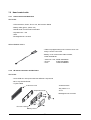
1
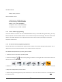
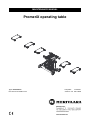
MAINTENANCE MANUAL
PromeriX operating table
Type: Instructions
Document: DO1085-2-2.en
Complete:
13.3.2007
Version: 2-2 29.1.2009
1
WARNINGS, NOTES AND INSTRUCTIONS
5
2
GENERAL
10
3
4
2.1 Intended use
10
2.2 Operating characteristics
11
CLEANING
3.1 Cleaning instructions
12
3.2 Cleaning
12
3.3 Disinfection
12
3.4 Mattresses and pads
12
MAINTENANCE INSTRUCTIONS
4.1 Safety during maintenance procedures
13
13
4.1.2 Monthly service
13
4.1.3 Annual service
14
TECHNICAL DATA
5.1 Identification plate
5.1.1 Illustrated designations and symbols
14
18
18
18
5.2 Properties and materials
19
5.2.1 Surface materials
19
5.3 Specifications
6
13
4.1.1 Daily service
4.2 Troubleshooting and checklist
5
12
20
5.3.1 Environmental specifications
20
5.3.2 Electrical specifications
20
5.3.3 Classification data
20
5.3.4 Adjustment ranges
21
5.3.5 Weights and dimensions
21
MAIN COMPONENTS
22
6.1 Structure
22
6.2 Removal of casings
23
6.2.1 Table base casings
23
6.2.2 Column casing shrouds lifted up
23
7
6.2.3 Removing the column casings
24
6.2.4 Replacing castors
24
ELECTRONICS
7.1 Special user attention
25
7.1.1 Warnings
25
7.1.2 Block diagram
26
7.2 Battery
27
7.2.1 Replacing the battery
27
7.2.2 Battery charge
27
7.2.3 Storage of batteries
28
7.3 Power supply unit
28
7.3.1 Specifications
29
7.3.2 Replacing power supply
29
7.4 Mains fuses
30
7.5 Hand control units
31
7.5.1 Hand control unit MV-CUC01
31
7.5.2 IR-remote controller unit MV-CUI01
31
7.5.3 Device address programming
32
7.5.4 IR-remote control programming sequence
32
7.5.5 IR-receivers
33
7.6 Override panel MV-CUO 01
33
7.7 Foot switch
34
7.8 Level sensor
34
7.9 Inductive sensor
35
7.10 Wire sensors
35
7.11 Sensor connections
36
7.12 Motion Process Controller MV-MPC01
37
7.12.1 General
37
7.12.2 Communication
37
7.12.3 PC connection
37
7.12.4 Connectors
37
7.12.5 Cables
38
7.12.6 MPC connections
38
7.13 Solenoid pin connector configuration
8
25
HYDRAULICS
8.1 Safety information
39
40
40
8.1.1 Lift column
40
8.1.2 Warnings
40
8.2 Hydraulic unit
41
8.2.1 Removing the hydraulic unit
42
8.2.2 Hydraulic oil
42
8.3 Main valve block TLC3
8.3.1 Hydraulic circuit diagram
44
8.3.2 Substitution of TLC3 manifold
45
8.3.3 Exchange of TLC3 valve
47
8.3.4 Changing of solenoid coil at SP1 and TLC3 (valve system)
49
8.3.4.1 Remove the housing of the solenoid
8.4 Cylinders
49
50
8.4.1 Distribution block of table with sliding function
50
8.4.2 Distribution block of table without sliding function
51
8.4.3 Cylinder types
51
8.4.3.1 Leg and back section cylinder hose connections
51
8.4.3.2 Height cylinder connections
52
8.4.3.3 Trendelenburg cylinder connections
52
8.5 Floor lock cylinder type LF16
53
8.5.1 Connections
53
8.5.2 Cylinder type
53
8.5.2.1 Features
9
43
53
8.5.3 Floor lock support leg adjustments
54
8.5.4 Pressure switch and SP1 valve block
54
8.5.5 5th wheel cylinder block connection diagram
55
8.6 Seat section joint shields
56
8.6.1 Replacing joint shields
56
RECYCLING
57
9.1 Metals and plastics
57
9.2 Hydraulic cylinders and gas springs
57
9.3 Oil
57
9.4 Electronic waste and batteries
58
ORDER FORM
59
NOTES
60
Compiled by: Harri Uusitalo
Approved by: Arto Koski-Laulaja
_______________________________________
Date: ___ . ___ . _______
1. WARNINGS, NOTES AND INSTRUCTIONS
!
In order to ensure optimal surgical safety, all operating table users should carefully read the operating table
and maintenance instructions before using the table. The entire surgical ward staff should be familiar with the
correct use of the PROMERIX operating table as well as all warnings and observations concerning it.
Warnings and observations found in this instruction manual are indicated as follows:
!
!
WARNING!
Please observe to ensure patient safety.
CAUTION!
Please observe in order to avoid causing damage to the equipment or its parts.
NOTE!
Please observe in order to improve operating table properties.
WARNINGS!
!
PromeriX operating table should only be used in facilities made for medical purposes.
!
IP X4 classification is valid only when the mains cord is disconnected.
!
Connect the mains cord only to earthed power supply.
!
PromeriX shall be operated from it’s internal battery if the integrity of the protective earth conductor
!
!
!
arrangement is in doubt.
Place the patient in the longitudinal center line of the table top.
In NORMAL mode max. patient weight with sliding seat section is 275 kg ( 600 lbs ).
In NORMAL mode max. patient weight without sliding seat section is 325 kg ( 700 lbs ).
In REVERSE mode max. patient weight is 180 kg ( 400 lbs ).
!
Adjust the table top to the horizontal position ( 0-position ) with the hand control unit before transporting a
!
Transporting of patients weighing up to 180 kg ( 400 lbs ) is only allowed when table top is in horizontal posi-
patient on the operating table.
tion ( 0-position ) and the height of the table is max 900 mm ( 3 ft ).
5
WARNINGS, NOTES AND INSTRUCTIONS
!
!
!
Transporting of patients weighing 180-225 kg ( 400-500 lbs ) is only allowed when the table is in NORMAL
mode, in horizontal position ( 0-position ) and in the lowest position.
Transporting of patients weighing 225-325 kg ( 500-700 lbs ) is not allowed.
!
Use extreme caution when transporting the table with a patient on. Transporting of the table with a patient on
!
To avoid endangering the patient's respiratory system, nerve pathways and circulatory system, the patient
!
Check that table top sections catches lock correctly. Incorrect attachment of table sections is dangerous and
!
!
requires two persons. To maximize patient safety utilize proper restraint methods during transport.
should be positioned properly and kept under observation!
can cause personal injury or equipment damage!
Use only accessories recommended by the table manufacturer.
When adjusting the operating table, take care to avoid collision between accessories and the operatingtable.
!
Do not use worn or damaged accessories. When using the table, ensure that all accessories are properly
!
When adjusting the operating table, take care that the fingers, hands or other parts of the body of the patient
mounted and check the function of accessory locking and adjustments.
are not placed between edges of back, leg or seat section frames and pivoting points.
!
Use only permitted table top configurations illustrated in this manual.
!
Ensure before adjusting the operating table that table top will not hit external obstacles.
!
!
Ensure before adjusting the operating table that NORMAL/REVERSE mode has been chosen correctly and is
the same as patient's orientation on the table top. After use of main switch NORMAL mode is set as default.
Always follow manufacturer instructions when using diathermy or defibrillation equipment.
When using high frequency surgical equipment take care to prevent the patient coming into contact with
!
metal parts of the operating table or accessories. Do not place the patient on wet or damp surfaces or electri-
!
Combustible anaesthetic gases must not be used with the Promerix operating table.
cally conductive pads. Hazard of burn injuries!
6
WARNINGS, NOTES AND INSTRUCTIONS
!
!
Use potential equalization conductor with patient monitoring equipment. Connector placed at the table base.
!
When recharging the battery first plug the mains cord to table appliance inlet, after that to wall socket.
Main switch can be used as an emergency stopping device ( demanded by the standards ). Normally the
!
switch lever is in up position. When the lever is turned down in OFF position all table functions are cancelled.
!
When recharging is completed disconnect the mains cord first from the wall socket, after that from the table
!
!
Table movement stops immediately.
appliance inlet.
Disconnect the mains cord from the table and turn the main switch to OFF position before cleaning of the
table.
Disconnect the mains cord from the table before any service procedures. 100-240 V ~ used in power unit
placed in table base. Hazard of electric shock!
Promerix operating table has been tested to EN 60601-1-2 to ensure proper electromagnetic compatibility.
!
Other products used in the vicinity of Promerix operating table should also comply with this standard. If they
do not comply, interference between products in unintended responses may occur. Please contact the
appropriate manufacturer if any problems arise.
!
Portable and mobile RF-communications equipment can affect Promerix operating table.
7
WARNINGS, NOTES AND INSTRUCTIONS
!
CAUTIONS!
!
!
!
!
!
!
!
!
!
!
!
!
!
If the operating table has been in the cold, allow it to warm up at room temperature for at least 6 hours before
recharging the battery or switching on, to allow any condensation formed to evaporate.
Recharge the battery prior to use. See the starting instructions attached to table base panel.
OVERRIDE panel is only for returning the table top to the horizontal position in the case of electronic malfunction. Override makes it possible to adjust table without the controlling processor and any of the programmed restrictions are not functioning.
Downwards adjusted leg or back section may hit the table base or column casings depending on the used
height or tilt angle adjustments. Can cause damage to the operating table and creating pinching hazard!
Do not place any objects on the base of the operating table! Danger of damage during adjustments!
The best place to store the hand control unit especially during transport is the lever under the head section.
Head and devided leg section 60475 gas springs can be disposed of as metal waste after nitrogen gas and
oil has been removed. Instructions for gas releasing available from your sales representative.
Operating table has been classified as splash proof equipment. Use of pressurized water is not allowed.
Cleaning and disinfecting should be made according to this manual.
Do not pull or push the shields of back and leg section joints. Check during adjustment that there is no foreign obstacles between shields.
It is possible to adjust the SLIDE adjustment only when back or leg section are in horizontal or above horizontal position. Slide adjustment will stop automatically before collision if back or leg section in under the
horizontal position.
SLIDE adjustment is only possible when table top is in horizontal position. Use of SLIDE adjustment is
restricted with tilted table top.
Mattresses should be cleaned only with neutral detergent ( ph 7-8 ).
The antistatic properties of the operating table require the use of original brand mattresses and antistatic
flooring.
8
WARNINGS, NOTES AND INSTRUCTIONS
!
NOTES!
It’s recommended to recharge the battery overnight after day’s use. Table will be always ready for use and
the battery will have longer service life.
If the main switch is turned to OFF position ( downwards ), all table functions are blocked including recharging of the battery. Check that the green led above the charging inlet lights up when you connect the mains
cord to the table.
When mains cord is connected to operating table the cooling fan of the power unit is activated causing a
humming sound. After disconnecting the mains cord the cooling fan still runs for few seconds.
Turn the main switch to OFF position ( downwards ) when the table is not in use or stored for longer period of
time. This eliminates the possibility of unintended use and is also saving the battery capacity.
Activate the floor lock before adjusting the table. Only trendelenburg and back rest adjustments are functioning if floor lock is not activated.
Cardboard packing material should be recycled. Wood and plastics are energy waste.
Batteries contain lead and if replaced, need to be recycled in accordance with local environmental regulations.
Velcro tapes on table top plates can be cleaned with pressurized air. Velcro tape can also be replaced; spare
parts and instructions available from Merivaara service dpt.
Floor lock can be deactivated with a release knob placed at the table base if normal deactivating with hand
control unit or override panel can’t be done. Turn the knob 90° clockwise and the table will descend on to its
castors. Turn the knob back to its original position after releasing.
9
2. GENERAL
Merivaara Corporation conforms to all its operations ISO 9001 Quality Management and ISO 14001 Environmental Management System Standards. In addition the Promerix operating table meets the following standards: EN 60601-2-46, EN 60601-1-2 ( EMC ) and EN 60601-1. The table complies with directive 93/42/EEC (
MDD ) product class I, and bears a CE marking based on this classification.
2.1 Intended use
Promerix Operating Table is intended for general surgical use. It is also well suited for:
• Day surgery
• ENT surgery
• Plastic surgery
• Orthopedics
• Arthroscopy
• Gynecology
• Urology
• Pediatrics
• Neurosurgery
Expertise is essential
The patient is the most important part of treatment. This is precisely why
the equipment used in treatment must be absolutely
safe and convenient to use. As a health care
professional, you deserve the very best tools,
allowing you to concentrate on your own field of
expertise. Merivaara is an expert in providing
hospital equipment.
Merivaara products have been designed to function
efficiently and flexibly during the various stages of
treatment. They assist you in the performance of
your work, without distracting you from the task at
hand. Our modular equipment system includes
state-of-the-art equipment for hospital procedures
and hospital room environments as well as for
nursing homes and home care applications.
For more information on Merivaara products,
contact our Sales Office. For matters related to
equipment servicing, contact the Merivaara Service Department.
10
2.2 Operating characteristics
Promerix is transportable electrohydraulic battery and mains operated operating table. It is microprocessor
controlled and it‘s function parameters are reprogrammable with special PC-operated service program. Table
can be connected to 100….240 VAC mains power and its secondary voltage is 24 VDC. The table electronics
are safely earthed and it has equipotential connection.
Table top consists of fixed or sliding seat section and detachable 25 and 40-sections. You can rearrange the
sections as you wish depending on the surgical concept and operation. Look page 14. The width of the table
top is 540 mm, ( 21 1/4 inch ) without rails and length 2100 mm ( 82 inch ). Table top plates are x-ray translucent material.
Promerix can be adjusted with cable connected hand control unit, IR-hand control unit or foot switch. Operating table can also be adjusted with override panel in case of electronical malfunction ( hand control unit or
table microprocessor defective ).
Safe and fault-free use and maintenance of the equipment requires careful acquainting to these instructions.
When mounting accessories to the equipment, the instructions provided with them must be followed closely.
Always keep the instructions for accessories together with this manual.
11
3. CLEANING
3.1 Cleaning instructions
!
!
!
!
Disconnect the mains cord from the table and turn the main switch to OFF position before cleaning of the
table.
Operating table has been classified as a splash proof equipment. Use of pressurized water is not allowed.
Cleaning and disinfecting should be made according to this manual.
Do not pull or push the shields of back- and leg section joints. Check during adjustment that there is no foreign obstacles between the shields.
Surface of the Promerix mattresses is electrically conductive. Cleaning of the mattresses should be done with
neutral detergent( pH 7-8 ) and warm water applied with a single use wipe.
3.2 Cleaning
•
Remove accessories and mattresses.
•
Clean by wiping down with a mild alkaline detergent ( pH 7-8 ).
3.3 Disinfection
•
Remove accessories and mattresses.
•
Disinfect only when necessary.
•
Wipe down the equipment with the surface disinfectant used at the facility in accordance with manufacturer instructions, unless the surface disinfectant contains phenols and alcohol, which can corrode
plastic parts and mattresses.
!
!
NOTE!
Dry the operating table carefully immediately after cleaning or disinfecting.
3.4 Mattresses and pads
Read the care instructions for mattresses and pads.
12
4. MAINTENANCE INSTRUCTIONS
4.1 Safety during maintenance procedures
!
Maintenance allowed only to persons specialized to Promerix service work.
!
Disconnect the mains cord from the table before any service procedures. 100-240 V ~ is used power unit
!
Turn the main switch to OFF position before connecting or disconnecting any of electronic connections or
!
Static charges can cause sparks harming sensitive electronic components. Ground yourself to metallic parts
!
placed in table base. Hazard of electric shock!
components in order to protect them against voltage surges.
of table before touching electronic components.
Disconnecting any of the hydraulic hoses can cause uncontrolled and dangerous movement of the table.
Support the table parts before disconnecting any hydraulic hoses!
When mains cord is connected to operating table the cooling fan of the power unit is activated causing a
humming sound. After disconnecting the mains cord the cooling fan still runs for few seconds.
4.1.1 Daily service
•
During normal cleaning, check-up general condition of the operating table. Contact service personnel
if needed.
•
We recommend that you charge the table battery every day. This is to ensure sufficient battery charge
level and long service life.
•
Check the mains cord condition.
•
Promerix operating table must be cleaned carefully after each surgical procedure!
4.1.2 Monthly service
•
Clean and lubricate guide pins, latches, spring-loaded pins and pivoting points with light machine oil
or spray vaceline.
•
Check that castors roll smoothly and floor lock is functioning correctly.
•
Test table functions by adjusting them to their extreme positions.
13
•
Check hand control unit and foot switch cables, connector and plug.
4.1.3 Annual service
•
Perform all daily and monthly service actions.
•
Check the functioning of table section's latches.
•
Check all cables and connectors, regarding injuries (kinks, cracks, wear)
•
Visual check at the hydraulic hose connections and piston rods, regarding external leakage.
•
Check of the oil level in the reservoir of the oil pump, if the level is too low fill up with filtrated
mineral oil (ARAL VITAM DE32).
•
!
Oil change: every 5 years
All electrical repairs must be performed by a licensed electrician.
4.2
Troubleshooting and checklist
POSSIBLE SITUATIONS:
PROBLEM:
Table will not activate when pressing ON/OFF-button
PROCEDURE:
CAUSE:
-Main Switch in OFF position
Turn to ON position
-Hand Control Unit not connected properly
Check the connection
-Faulty Hand Control Unit
Replace the hand control unit
-Broken Hand Control Unit cable
Replace the cable
-Empty batteries
Connect mains cable
and recharge batteries
-Battery fuse blown
Check and replace
-Faulty MPC
Replace MPC
14
!
PROBLEM:
Table adjustment not functioning when pressing function
button, table activated
PROCEDURE:
CAUSE:
-Floor lock not activated
Press activation button
-Making adjustment table program restricts
Check the table positioning
-Adjustment already in its end position
Check the table positioning
-Faulty hand control unit or IR-control unit not programmed correctly.
Check the control unit
PROBLEM:
Table movement won’t stop although function button is
released
PROCEDURE:
CAUSE:
-Severe functioning failure of electronics. Malfunctions are
always recorded in the Error Log.
MAIN SWITCH to OFF
position!
Use service program
manual to resolve error
code.
-Faulty hand control unit
MAIN SWITCH to OFF
position!
Contact service
-Valve is mechanically stuck or stays open constantly
Contact service, new
valveblock or
solenoid is needed
-Short circuit in the transistor controlling the solenoid
Contact service
-Damaged solenoid or sensor wires
Contact service
PROBLEM:
Back section moves when leg section button is pressed or
vice versa
PROCEDURE:
CAUSE:
-Normal/Reverse – mode wrongly selected
Check the selected
mode
!
PROBLEM:
Audial signal when using IR-hand control unit
PROCEDURE:
CAUSE:
- Indicates that the operating table floor lock is not activated!
Press the floor lock button steadily!
- Cause no marking into the Error Log
Reset by pressing the
ON/OFF button.
15
PROBLEM:
Table not responding to IR-hand control unit commands
PROCEDURE:
CAUSE:
-Control unit wrongly aimed
Aim towards the table
-Distance between table and control
Check the distance
-IR-receiver blocked
Check
-IR-control unit battery depleted
Replace batteries
-IR-control unit wrongly coded
Set codes again
!
-Emergency situations use override panel buttons!
PROBLEM:
Table motion stops during adjustment
PROCEDURE:
CAUSE:
- A simultaneous commands will stop the table movement
Release another of the
pressed buttons
- Can cause if foot control and hand control units are pressed
at the same time.
Use one control unit at
the time
PROBLEM:
One piece leg section can not be adjusted
PROCEDURE:
CAUSE:
-One piece leg sections not attached to seat section correctly
Check the latches
-Faulty inductive sensor
Contact service
PROBLEM:
Hydraulic unit starts but no movement occurs
PROCEDURE:
CAUSE:
-Valve block solenoid defective or loose
Contact service
-Table adjustment in its end position
Check the table positioning
The table changes position by itself
PROCEDURE:
- Control unit buttons are accidentally pressed or pinched
Check the control unit
PROBLEM:
16
CONTACT:
Further information of PromeriX service, product support and spare parts are available from your local dealer
or from Merivaara Corp.
Merivaara service
+358 3 3394 6152
Merivaara service fax
+358 3 3394 6249
E-mail
[email protected]
Internet
www.merivaara.com
17
5. TECHNICAL DATA
5.1 Identification plate
Identification plate is located in the joint, under of the seat section.
Consult accompanying documents
Primary voltage and frequency
Manufacturing date
Ingress Protection
Splash proof
Safe max. working load
CE approved device
B-type applied part
ID-plate
5.1.1
Illustrated designations and symbols
Equipotentiality
Protective grounding
~
Alternating current
B-type applied part
!
Attention, consult accompanying documents
275 kg
=180
Maximum load with slide ( including patient, mattresses and accessories )
325 kg
=180
Maximum load without slide ( including patient, mattresses and accessories )
18
5.2 Properties and materials
5.2.1
Surface materials
Surface materials used in Promerix table with possibility to skin contact:
Epoxy coated steel
Frame constructions
Zinc plated steel
Frame constructions
Stainless steel
Accessory rails, casings, frame constructions
Aluminium bronze
Pivots
High pressure laminate
Table top plates
PUR
Mattresses
Anodized aluminium
Table top section sides
Polycarbonate ( PC )
Hand control unit B-cover and battery cover
Silicon
Hand control unit A-cover
EPDM-rubber
Bellows
ABS+PMMA
Base and castor covers
PC/ABS-composite
Override panel
ABS
IR-receivers
19
5.3 Specifications
5.3.1
Environmental specifications
Promerix is designed to be used in following environmental conditions:
Ambient temperature
+10 ... +40 °C
Ambient pressure
700 ... 1060 mbar
Relative humidity
30 % ... 75 %
Transport temperature
- 10 ... +40 °C
Storage temperature
+10 ... +40 °C
5.3.2
!
Electrical specifications
Primary voltage
100 - 240 V~
Frequency
47 - 63 Hz
Secondary voltage
Nom. 24V DC
Maintenance free sealed lead
acid battery
24V / 18 Ah
Max. power consumption
600 W
Main fuses
F10A ( 5x20 2 pcs )
Normal recharging time
5 - 10 h ( depending on battery
charge level )
Operation time with full battery
approx. 180 min.
Max. uninterrupted operating time
2 min / 10 min ( ED 20 % )
If you would like more detailed information, please contact the Merivaara service department.
5.3.3
Classification data
Promerix is classified according to EN 60601-1 as follows:
Electric shock protection
Class I equipment, internally powered
Degree of electric protection
B-type
Protection against liquids
IP X4 / Splash proof equipment
Cleaning and disinfecting
According to instructions, on page 13
Operating Rate
Intermittent operation / ED 20%
Protection against flammable anaesthetic gases
Do not use with combustible gases
Safe working load
325 / 275 / 225 / 180 kg incl. patient, mattresses and
accessories.
20
5.3.4
Adjustment ranges
WITH SLIDE
WITHOUT SLIDE
Height
650 - 1110 mm
610 - 1070 mm
Longitudinal shift
410 mm
Lateral tilt
± 25°
Back section
- 45° ... +80°
- 45° ... +80°
( +4° / -1°...+1° / -4° )
Leg section
- 105° ... +70°
- 95° ... +70°
( +4° / -1°...+1° / -4° )
Trendelenburg and antitrendelenburg
± 35
Headrest ( Std. )
- 45° ... +45°
5.3.5
-
( 0 / +10 mm ...+/ -5 mm )
( 0 / -10 mm )
+ 20°
( ±2,5 ° )
± 35
( ±2,5 ° )
- 45° ... +45°
( 0 / +5 °...0 / -5 ° )
Weights and dimensions
WITH SLIDING FUNCTION
WITHOUT SLIDING FUNCTION
Table top
6-sections
6-sections
Weight of table
325 kg
300 kg
Length (A)
2100 mm
2100 mm
Width (B)
610 mm
610 mm
Height (C)
650 - 1110 mm
610 - 1070 mm
Lenght of the base (D)
1200 mm
1200 mm
Table top width without rails (E)
540 mm
540 mm
Table top width with rails (F)
594 mm
594 mm
Floor clearance (G)
25 mm ( 0 / + 3 mm )
25 mm ( 0 / + 3 mm )
Castors Ø
125 mm
125 mm
Longitudinal Shift
410 mm
-
Castors distance (H)
1100 mm
1100 mm
Dimensional drawing
A
F
E
250
500
400
400
250
G
C
301
H
D
B
21
6. MAIN COMPONENTS
6.1 Structure
25-section
40 gyn-section
Seat and sliding section
Distribution block
Back section
25-section
Head section
Back and leg section
cylinders
Casing shroud
Override panel
Lifting column
Floor lock valve block
Hydraulic unit
Power supply
Battery
Main valve block
MPC
Cylinder for
Trendelenburg
Castor
Base frame
Main switch, fuses and
charging socket
CONTROL DEVICES:
IR-remote control
Foot control
22
Hand control unit
6.2 Removal of casings
6.2.1
Table base casings
5
4
3
1
2
!
Disconnect the mains cord from the table and turn the main switch to OFF position before removing any casings!
•
Remove screws from the lowest protective casing shroud ( 1 ) 4 pcs.
•
Remove plastic head screws from both sides of the base casings ( 2 ) 4 pcs.
•
Lift the lowest casing shroud ( 3 ) slightly up and pull the Rear base casing cover ( 4 ), Front casing
cover ( 5 ) away from the end of the table.
•
6.2.2
Assemble the casing in reverse order.
Column casing shrouds lifted up
2
1
•
Check that the table is its highest position, for better access.
23
•
Lift the casings (2) up, within each other and hang under the seat section of the table top or support
with suitable braces.
!
You don‘t have to remove casings completely in all situations.
Assemble the casing in reverse order.
!
6.2.3
Removing the column casings
If you need to remove column casings completely, e.g. changing sensors, disassemble shrouds one by one.
•
Starting on lowest casing shroud.
•
Look at the section 6.2.1. Remove screws (1) 4 pcs which are fixing the lowest column casing shroud
to the base.
•
Remove the shroud piece fixing screws 4 pcs with 2 mm Allen wrench. You may need to push shroud
pieces slightly inwards because of shroud sliding brackets.
6.2.4
!
Replacing castors
Before you get access to remove castors you have to use ramp or lift up the operating table from the ground.
One bearing is installed top of the frame and another in the base of the castors shaft.
Castors are fixed with M6 bolts. Removing with 5 mm Allen wrench.
- 1 pcs fixing bolt
Fixing bolt
- 1 pcs washer
- 1 pcs plastic washer
Washers
- 2 ball bearings, lubricated
for life
24
7. ELECTRONICS
7.1 Special user attention
To assure the highest degree of operating safety all the users of the operating table should carefully
familiarize themselves with the instructions for use and maintenance manual before use of this table. Aquainting your operating personnel to only proper use of the Promerix operating table and also to the warnings,
cautions and notes relating to it.
7.1.1
!
!
Warnings
When adjusting the table take care that the fingers, hands and other parts of the body of the patient are not
placed between edges of back / foot or seat section frames and pivoting points.
Disconnect the mains cord from the table and turn the main switch to OFF position before touching or removing any electronic components!
!
Ensure to full, appropriate functioning after repairing, connections must be performed with using approved
!
Installation must be done according to local regulations and standards. If any doubt, consult a licensed tech-
components.
nician.
25
86%
7LOW6OLGHRU%DFN
26
390
152
/HG
088726
LQ9
RXWQRP9
3RZHU&KDUJHU
(0,)LOWHU
%DWWHU\
9$K
,55HFHLYHUV
7(.,-b
-86825$-
0DLQVZLWFK
7UHQG
7LOW
/HYHOVHQVRU
86%
+HLJKW
$SSOLDQFHLQOHW
)XVHV
2YHUULGH
6,'1(
+<9b.6
%DFN
/HJ5,QGVHQVRU
+HLJKW
%/2&.',$*5$0
(/+<'&20321(176
3520(5,;
3,17$.b6,77(/<
/$678$0,1(1,62P.
+,76$7875$.(17((7(1,62%(
1,0,7<6
0$7(5,$$/,
.3/
9$
9$
9$
0
9$
6OLGH
72/(52,0$7720,(10,772-(1
7<g7$3$.2+7$,6(772/(5$166,7
26$152 1,0,.(781186
0RWRURXWSXWV
03&
%DFN
7LOW
2SWLRQ
0
0
0
RSWLRQ
RSWLRQ
6OLGHPRWRU
+<9b.6
3,,57b1<7
-86825$-
$
0,77$.$$9$ 0$66$.* 3,17$$/$'0 78/267(778
.*26$
9DOYHEORFN
WK:KHHO
)ORRU/RFN
+\GUDXOLFXQLWPRWRU
7UHQG
1,0,7<6
9$
/HJ5
)ORRU/RFN
6DIHW\HGJHV 2SWLRQGLJL
+HLJKW
3UHVVXUHVZLWFK
6DIHW\HGJH
:LUHDQG,QGVHQVRUV
/HJ/,QGVHQVRU
/RJLFLQSXWV
)RRWVZLWFK
7UHQG
2SWLRQDQD
+DQGSDQHO6LGQH
3RZHULQSXW
/HJ/
2YHUULGH,5
)RRWVZLWFK
/HJ5
6ROHQRLGRXWSXW
,5+DQGSDQHO
WKZKHHO
/HJ/
+DQGSDQHO
6DIHW\HGJH
7.1.2
Block diagram
7.2 Battery
Two 12 V batteries connected in series.
Nominal Voltage
2 x 12 V
Nominal Capacity
18 Ah
Dimensions (LxWxH, mm)
181 x 76 x 167
Approximate weight
6.2 Kg
Internal Resistance (Fully charged battery) 10.5 mΩ
Maximum charging current
4.5 A
Terminals
Bolt and Nut M5
Torques
4.5 Nm
Storage temperature
-20°C to 40°C
Operative temperature range
Charge__________________0° C to 40°C
Discharge_______________-20°C to 50°C
Case material
7.2.1
Acrylonitrile-Butadiene-Styrene
Replacing the battery
4
5
•
tion.
•
6
Turn the operating table main switch to OFF-posiRemove the front casings of the table base, check
section 6.2.1 at the page 23 .
7
8
6
•
Unplug the electric conductor (1)
•
Remove the screw (2) holding the battery frame
(outside of the base) look at the page view A.
1
look at the page 29 view A. Remove the screws (4)
7
and cover (5)
2
3
•
Disconnect the wire sets (6)
CODES:
- Bettery assembly
- Battery
- Fuse
7.2.2
Battery charge
•
Voltage measurement
•
Current limitation and measurement
•
Constant voltage charging 27,8 V
27
A31596800
7133593 (7)
71342542 (8)
LED indication for battery and charge state
- Green LED = Battery OK
- Yellow LED = Lowered battery capacity
- Flashing yellow LED = Not fully charged
- Flashing green LED = Fully charged battery (charge current is less than 150 mA which means
- > 80 % of total capacity, still charging).
- Red LED = Battery empty, connect to powerline
Charging continues all the time when power is connect to line.
Indication level parameters can be changed with PC Service Program.
7.2.3 Storage of batteries
Batteries should be storaged in a dry, clean condition and charged before storing. At a storage temperature
of 20° C, batteries should be re-charged after 8 months. At higher temperature, re-charging should take
place more frequently. Discharged batteries should be re-charged within one week.
!
WARNING !
Do not open the vents. Replace always both batteries together. Use only the
batteries delivered or recommended by the manufacturer. Notice local disposal
regulations.
7.3 Power supply unit
Medical rated Power supply
code: A41788100 without fixing bracket
Secondary voltage set screw 2
Secondary voltage set screw 1
Base fixing bolt
Line
Unit fixing bolt
28
Ground
Neutral
7.3.1
Specifications
100 - 240 V ~
Input voltage, alternating current
47 - 63 Hz
Frequency
27,8
Output voltage, direct current
115 °C
Overtemperature protection, measured internally
600W
Output power
Output overvoltage protection 110-140 % V nominal
CE\UL\CSA approved device.
7.3.2
Replacing power supply
!
All electrical repairs must be performed by a licensed electrician.
!
Disconnect the mains cord from the table before any procedures.
!
Cases when you have to replace power supply unit, read well all the warnings, specifications and notations.
!
Work only when the table is de-energized state.
!
!
Check and mark all cable connections before removing.
Use professional, protected tools.
29
- Power supply is fixed with two bolts which you can screw out with 5 mm Allen wrench.
Fixing bolt
'(7$,/%
6&$/(
Power supply
$
'(7$,/$
6&$/(
Holding the battery frame
%
7.4 Mains fuses
!
Mains receptacle includes 2 x F10A fuses, which can be easily changed. Turn the main switch OFF before
continuing.
2 pcs 5X20 fuses
Code: 71342751
Push-in fuses
Fuse box
Appliance inlet
Push the sealing plug side clips simulta-
PUSH
neously and pull the plug cover out from
PUSH
the receptacle!
Sealing plug
30
7.5 Hand control units
7.5.1
Hand control unit MV-CUC01
FEATURES:
- LED indications; Orient, Floor Lock, 5th Direction Wheel
- Battery state (green, yellow, red)
- RS232 serial communication with MPC
- Key Matrix 4x7 =28
- IP-54
- Backlight Boost converter
REPLACEMENT PARTS:
- Cable is equipped with quick connector which can
easily connect to the PCB
- Battery cover module with cable installed,
CODE A41809700
- A-silicone cover, CODE A21560600
- B-cover
CODE A41809600
- Hook
CODE A41829300
7.5.2
IR-remote controller unit MV-CUI01
FEATURES:
- Same PCB as in hand panel but with different components
- Micro chip PIC16LF874A
- Crystal 4 MHz
A-silicone cover
- IR-transmission
- Key matrix 4 x 7
Suspension hook
- IP 54
-Backlight boost converter
B-cover housing
Battery cover
31
LED INDICATION:
- Battery state green/red
REPLACEMENT PARTS:
- A-silicone cover, CODE A41811100
- B-cover housing, CODE A41809600
- Battery cover, CODE A31638600
- Suspension hook, CODE A41829300
- AA-batteries 4 pcs, CODE 71335974
7.5.3
Device address programming
An device address is saved in the non-volatile EEPROM memory of each table during final testing. The only
table movement commands that the table‘s microcontroller accepts are IR-messages, which are send via this
address. The table addresses can be programmed remote controls memory following the instruction
sequense shown below.
7.5.4
IR-remote control programming sequence
Device instructions uses double button press functions, which are not used during normal operatio. This is
designed to prevent accidental activation of the address selection sequence.
The address search/instruction process goes as follows:
1. Point the remote control at the operating table.
2. Press the backlight
button while pressing the buttons on the right side of the remote control one
after the other from bottom to top.
3. When the operating table buzzer gives two consecutive tones, the correct address group has been found.
4. Keep the backlight button pressed down.
5. While holding the backlight button press the buttons for rows found in above section 3 on the left side of
the remote control.
32
6. Keep the buttons pressed down untill the operating table buzzer begins to send short, rapidly repeating
tones. The tones will sound in 2 seconds, during which time the buttons on the left should be released. If
the buttons are held down the tone will sound in 16 second intervals.
7. Release the backlight button. The operating table buzzer will then give a long tone. The table‘s individualised device address is now saved in the remote controls memory.
8. The operating tables mechanical movements can be controlled with this remote control after the instruction sequence. The saved device address is maintained in the remote controls non-volatile memory, even
when changing the batteries.
7.5.5
IR-receivers
- Infra-red transparent ABS-cover
- 2 pcs
- Fixing bolts inside the column shrouds
- Protected with polyurethane tape
-CODE A41617700
7.6 Override panel MV-CUO 01
FEATURES:
- Key(s) with simultaneous multiple inhibition
1
- LED Indications; Orient, Floor Lock,
5th Wheel, Battery state (green, yellow,red)
- Buzzer oscillation circuit
- IR-receiver inputs
4
- Key panel (1)
3
2
- protective plug (2)
- Fixing nut (3)
CODE A41713500 with cables (fixing parts not included)
CABLE INTERFACES:
- USB for PC service software
- RS-232 for hand control (LEMO)
- Foot control connection (LEMO)
- Control/monitoring system connection (LEMO)
33
- Washer (4)
7.7 Foot switch
•
6 digital inputs with common ground.
•
Programmable
•
LEMO connector
•
Foot control, CODE 60850
7.8
Level sensor
NRO
PVM
MUUTOS
2
03.12.2007
Johtojen määrä ja väri muuttunut
TEKIJÄ
HYVÄKS.
JUSUORAJ
38
41
13,5
2
4,
Kaapelin pituus 1500 mm
2
Wire color
Name
White
Brown
Green
Yellow
GND
Vcc
Output X
Output Y
Function
Ground
Power supply
X-axis output
Y-axis output
Supply voltage: 5 +/- 0,25 V
Range:
+/- 90 °
Weight:
~60 g
Protection:
IP 66
Kiinnitys yläkiinnityskehään:
- 70611 M4x6 DIN 7984
- 2 kpl
OSA NRO NIMIKETUNNUS
NIMITYS 1
NIMITYS 2
TOLEROIMATTOMIEN MITTOJEN
TYÖTAPAKOHTAISET TOLERANSSIT:
MATERIAALI
MITTAKAAVA MASSA KG PINTA-ALA DM2 TULOSTETTU
LASTUAMINEN:
ISO 2768-mK
HITSATUT RAKENTEET: EN ISO 13920-BE
PINTAKÄSITTELY
KPL
1:1
KG/OSA
0.12
PIIRTÄNYT
0.01
18.1.2008
28.06.2005 JUSUORAJ
HYVÄKS.
NRO
PVM
MUUTOS
TEKIJÄ
HYVÄKS.
KULMA-ANTURI
VTI SCA121T-D09
PROMERIX
A7134361-2
CODE A7134361
!
NOTE!
After replacing level sensor reprogramming with service program is needed. Consult Merivaara
service department.
34
7.9
Inductive sensor
Sensor nominal voltage
24 V
Current type
DC
Wiring
3-Wire
Switching function
type NO
Output signal
PNP
Rated operational Voltage
24 V DC
Rated operational current
200 mA
Supply voltage
10...30 DC
Inductive sensor, type PNP
1
4
2
3
Sensor CODE A42108700
Spare part set CODE A31631500
- Sensor (1) is mounted inside leg section joints. Cable
WIRE CONNECTIONS:
is protected with protective mesh.
- Black, signal
- Sensor is fixed with locking screw (2) and plastic bushing (3)
- Blue, GND
- Cable is locked with locking screw (4) and wires are connected with wire end ferrules to terminal block, look at page 36.
- Brown, +24 V
- After installation, adjustment ranges must be tested
7.10 Wire sensors
- 0...5 V analog output
SENSOR CONNECTIONS:
1. +5 V, brown
3
2. Signal wire, white
1
3. GND, green
2
- Height, WPS-500, CODE 7134362
- Slide, WPS-250, CODE 7134363
- Back section, WPS-150, CODE 7134364
- Leg section, WPS-150, CODE 7134364, 2 pcs
35
36
24.10.2008
PVM
NRO
Sensor type
Slide
Back
Height
Leg left
Leg right
Leg left
Leg right
5th wheel
Floor Lock
Safety edge
Safety edge
Ind sensor
Ind sensor
Wire sensors
Wire sensor
Wire sensor
Ind sensors
Wire and Ind sensors
Wire sensor
Wire sensor
Wire sensor
Pressure switch
Pressure switch
Leg side
Back side
VTI-sensor
VTI- sensor
Tilt (Y)
VTI-sensor
Trend ( X)
VTI-sensor
Pressure switches/safety edges
Name
MUUTOS
Numbering starting from bottom as it is in the tables
Signal
Signal
+5V
Signal
Signal
+24 V
GND
Signal
Signal
Signal
+5 V
GND
Signal
Signal
+24 V
GND
Signal
Signal
Signal
Signal
Function
5
White L
White R
Pink
Grey L
Grey R
Brown
Green/Blue
White
Yellow
White
Brown
White
Yellow
Green
Red
Green
Black
Black
Black
Black
20
19
18
17
16
15
14
13
12
11
10
9
8
7
6
5
4
3
2
1
Colour
No
Wires from sensors
TEKIJÄ
JUSUORAJ
HYVÄKS.
Colour
7134341
Slide
Back
Height
Leg left
Leg right
Leg left
Leg right
ANTURIEN LIITTIMET
SENSOR CONNECTORS
PROMERIX
PINTAKÄSITTELY
LASTUAMINEN:
ISO 2768-mK
HITSATUT RAKENTEET: EN ISO 13920-BE
NIMITYS 1
LIITIN MSTBHK 2,5/10-G 5.08
HYVÄKS.
PIIRTÄNYT
29.07.2005 JUSUORAJ
A31605000-5
1:1
KG/OSA
0.1
0.1
MITTAKAAVA MASSA KG PINTA-ALA DM2 TULOSTETTU
15.12.2008
0.32
0.25
NIMITYS 2
PHOENIX CONNECTOR
PHOENIX CONNECTOR
Ind sensor
Ind sensor
Wire sensors
Wire sensor
Wire sensor
Ind sensors
Wire and Ind sensors
Wire sensor
Wire sensor
Wire sensor
5th Wheel
Pressure switch
Floor Lock
Pressure switch
Safety edge Leg side
Safety edge Back side
VTI- sensor
VTI- sensor
Tilt ( Y)
Trend (X)
Pressure switch/safety edges
Name
LIITIN PISTOKE MSTB 2,5/10-ST 5.08
MATERIAALI
KPL
2
2
Signal
Signal
+5V
Signal
Signal
+24 V
GND
Signal
Signal
Signal
+5 V
GND
Signal
Signal
+24 V
GND
Signal
Signal
Signal
Signal
Function
TOLEROIMATTOMIEN MITTOJEN
TYÖTAPAKOHTAISET TOLERANSSIT:
OSA NRO NIMIKETUNNUS
7134342
1
Yellow/brown
White/Yellow
White
Pink
Blue
White/black
Yellow
Black
Grey
Red
Brown
Green
Lila
Grey/pink
Brown/Black
Black
Grey/brown
White/grey
White/pink
Pink/brown
2
10
9
8
7
6
5
4
3
2
1
20
19
18
17
16
15
14
13
12
11
No
Wires from MPC/D-connector
7.11 Sensor connections
7.12 Motion Process Controller MV-MPC01
7.12.1 General
The MPC is installed on the surface of the outer tube of the column guiding system. CODE A41744800
- PC-programmable icrocontroller, PIC18F4550, Quartz crystal 12 MHz
- EEPROM memory for parameters
- Solenoid control (9x2=18 pcs) in main valve block
- Hydraulic unit motor PWM modulation and drive 15 A (single direction)
- Motor drives: 1 PWM 10 A (reversing), 2 pcs 5 A (reversing)
- Analog sensors: 8 (height, side tilt, Trendelenburg, slide, back section, leg
section (2 pcs) and 1 spare)
- Digital inputs: 8
- Error log
- Real-time clock
- RS-323 connection
- USB-connection
- Sleep mode wake up
7.12.2 Communication
- Hand control unit, IR control unit, override control panel
- Battery back-up
- Programmable positions
7.12.3 PC connection
- Parameter configuration (speed, start ramp, stop ramp)
- Automatic tests
- Hand control emulation
- System data (battery status, sensor readings)
- Test and service software updates
7.12.4 Connectors
- 15 Pin Female solder connector for remote controls
- 2 pcs 26 Pin Female solder connectors for override panel and sensors
- 44 Pin female solder connector for main valve block solenoids
- USB-connector
37
7.12.5 Cables
- Sensor cable
71165294 from OR panel to MPC
- Foot, Hand, Sidne controller cable
4530093 from OR panel to MPC
- IR receiver cable
4530112 from OR panel to IR receivers
- Override panel cable
4530091 from OR panel to MPC
7.12.6 MPC connections
Mounted on surface of a lifting cylinder quiding system, frontside of the table, fixed with M4 x 6mm screws.
Cable connectors tensioning screws are hand usable.
Foot switch and
remote control
Sensors
Override
USB
Solenoids
Battery,
hydraulic motor
!
NOTE!
Bottom view
Main valve block
solenoids
If MPC is replaced table‘s individual parameters must be reprogrammed. Consult Merivaara
service department.
38
7.13 Solenoid pin connector configuration
39
8. HYDRAULICS
8.1 Safety information
!
Before disconnecting any of the hydraulic lines, fittings, joints, hoses etc. be sure the attached table sections
are removed and the floor lock is OFF position. Failure of these precautions may cause an uncontrolled oil
spray and damage to the table or personal injury.
8.1.1
!
!
Lift column
Lift columns are operating agents which may be a risk to health or to material in case of incorrect handling,
improper application or insufficient maintenance. Therefore any work on the lift columns must be executed
by qualified persons only.
Fix the table top with belts or a similar equipment to a crane or support it by brackets. Otherwise
the table top can move downwards causing uncontolled movements.
8.1.2
Warnings
!
Work on the lift column only if it is disconnected, i. e. in a de-energized status. Protect
!
Hydraulic oil may cause skin irritations and other damages to health. Avoid skin being in
!
!
lift column against reactivation.
contact with for a longer period.
In case of damage of single components hydraulic oil may splash under high pressure.
For security reasons do not loosen any connections or devices while the hydraulic system is pressurized.
Before you open the system you have to ensure, that no load is on the cylinders or that the table top is supported by brackets.
!
Make sure everything is absolutely clean before working, because dirt can cause major
!
Equip all openings with protective caps so that dirt cannot penetrate into the system.
!
For cleaning hydraulic components use fluff-free materials only (no finery wool etc.).
!
!
damage to the hydraulic system.
Only fill oil into the system via a filter (10 µm); the system is filled with hydraulic fluid
ARAL Vitam DE32; this can be mixed with BP Energol HLP-HM32.
Exchange a hydraulic hose, if any damage (e. g. imprint or injury of the cover layer) is visible.
40
!
Use new sealing washers, if you open a hydraulic connection.
!
After you have replaced any parts, do a functional test with PromeriX service software without a patient on the
table or manually run with hand control all the movements to their min. and max. positions ( min. 5 times).
Jerky movements may indicate unnoticed inclusions of air. The system is completely evacuated, if all func-
!
tions are performed jerk-free, the system runs smoothly, and the surface of the oil level is without foam. The
system should evacuate automatically, if you move each cylinder from one internal stop to the other.
•
!
Recommended fastening torques for banjo bolts:
- M10x1: 14±1.5Nm
- M8x1: 10±1Nm
8.2 Hydraulic unit
• CODE A41951900
• Pump volume 0,24 cm3 / rev
• Motor size 0,2 kW / Nom 24 V
• Pressure relief valve setting 120 bar ±5 bar (1740 psi ±72.5 psi) (1 bar = 14.5 psi)
• IP 65
• Cables protected against interferences
Refill plug
Tank port
Pressure port
Pressure relief valve
Oil tank
Fixing screw code 70623
Ferrite rings
Cable: red +
Connector cover
Cable black -
Fixing plate
- Electric motor UL-listed: Dunkermotoren GR80x40
41
8.2.1
Removing the hydraulic unit
2
3
4
1
•
Remove casing screws, look at the page 23, lift out the casing brackets.
•
Disconnect main cord plug from the MPC.
•
Disconnect cables, and banjo fittings (2) 2 pcs.
•
Remove screws (3) 2 pcs from the fixing plate (4) and lift out the hydraulic unit (1) sideways.
8.2.2
Hydraulic oil
When checking oil level, first adjust table top to the horizontal and uppermost position. Oil level should be in
middle of pump reservoir.
•
Use ARAL Vitam DE 32 or BP Energol HLP-HM 32, CODE 71573 (1L)
Refill plug
Normal oil level
Oil reservoir
42
8.3 Main valve block TLC3
Left side valve ports: Plus-movement of the cylinder (piston rod coming outwards).
CODE A41798900
Fixed with two bolts
Pressure
Single banjo
bolt
Base block
Tank
Double banjo
bolt
Valve block
Height
Trend
$
Tilt
Back
Leg R
Leg L
Input
9,(:$
!
Dirt will cause malfunctions; therefore you have to ensure, that no dirt can contaminate the hydraulic
system.
HOSE CONNECTOR:
Codes:
M10 Banjo bolt
- M10 Short BANJO BOLT: A41766200
- M10 Long BONJO BOLT: A41766300
- M10 Sealing washer: A41766500
Tightening with torgue wrench to 14±1.5 Nm
Hose fitting part
Sealing washers, USIT-rings
43
8.3.1
Hydraulic circuit diagram
Drawing A41892100
44
8.3.2
Substitution of TLC3 manifold
• 6 solenoid valves
• 5/3-way spool valve and pilot operated check valve
• Nominal voltage 24 V
• Minimum working voltage 19 V
• Current consumption of solenoid 0.42 A
!
• Tightening of connectors 14 Nm (130 lbf.in)
Valve block
Throttle screw
Base block
Solenoid
Nut M5 with
tensioning bolt and sealing
plug
1. Lift the table top to the highest position. Install a wooden stick or similar device between the base
and the upper stage of lift column to fix the table in the extended position.
2. Retract the Trend, Tilt, Back and Leg cylinders completely.
3. Prepare the new manifold:
- Check, if the manifold is without any transport damage and if it is clean.
- Unscrew the yellow caps in the hydraulic ports and cover the manifold with a clean tissue.
4. Clean the manifold at the lift column.
5. Lay an absorbent tissue and a clean plastic box under the manifold.
6. Tie the two hoses of the double banjo bolts with a clip together (Height).
45
7. Unscrew the banjo bolts (hexagon 14 mm) at each hydraulic connection.
8. Unplug the electric connectors at the solenoids.
9. Unscrew the two M5 screws of the base block with an Allen wrench (4 mm).
10. Assemble the new manifold and tighten the two hexagon socket screws with a torque of 5,5±0,6Nm.
11. Plug the electronic connectors to the solenoids.
12. Check, if the rubber lip of the sealing washers is damaged. If yes, use a new one.
13. Connect the hoses to the connections of the TLC3 valves and tighten the banjo bolts (torque:14±1,5Nm).
!
Use new sealing washers (especially between the banjo and the valve body); check, if there are sealin washers between the manifold, the banjos and the bolt head.
14. Remove the clips at the hoses of the double banjo bolts.
15. Clean the hoses, valves etc. with a tissue.
16. Remove the plastic box and the tissue under the manifold.
17. Remove the wooden stick at the Height movement of the lift column.
46
18. Move all articulation at least 5 times to bleed the system (retract and extend the cylinders
completely).
19. Check, if there is external leakage at the hose connections or at the flange connections of the
valves.
20. Check the oil level at the tank of the power unit and fill it with filtrated hydraulic fluid Aral Vitam
DE 32, if required.
!
After all these actions functional test of the operating table has to be done.
8.3.3
Exchange of TLC3 valve
Coil for electric plug 24 V DC
Base block
Tensioning bolt
mountings
Solenoid housing
Process:
1. Lift the table top to the highest position.
2. Fix the table top with belts or a similar equipment to a crane or support it by brackets. Otherwise
the table top can move, if you disconnect the hoses at the valve. Retract the leg or back cylinders, if you want
to change one of these valves.
3. Lay an absorbent tissue under the valves.
4. Unscrew the banjo bolts (1) of the TLC3 valve (2) you want to substitute.
Close the banjo bolts with a M10x1 cap nut in order to stop the oil leakage.
5. Pull off the plug of the valve.
47
6. Fix the lower TLC3 valve with a belt to the base block (4).
7. Remove the plastic caps and loosen the three M5 nuts (3).
8. Unscrew the three tensioning bolts.
9. Pull out the faulty valve.
10. Assemble the new valve at the same position. Check the three o-rings at the flange connection of
all valves.
!
11. Screw the three tensioning bolts to the base block, install the three pairs of toothed washer and
tighten them with the M5 nuts (torque: 5,5 ± 0,6 Nm).
12. Connect the hoses to the ports of the TLC3 valve and tighten the banjo bolts (torque: 14 ± 1,5 Nm).
!
Use new sealing washers (especially between the banjo and the valve body). Check the sealing
washers between the manifold, the banjos and the bolt head.
13. Connect the plugs to the solenoids.
14. Remove the fixing belts.
15. Clean the hoses, valves, ... with a tissue.
16. Move the articulation of the substituted valve at least three times to bleed the system (retract and
extend the cylinders completely). Check, if there is external leakage at the hose connections or at
the flange connections of the valves.
17. Check the oil level at the tank of the power unit and fill it with filtrated hydraulic fluid Aral Vitam
DE 32, if required.
!
18. After all these actions functional test of the operating table has to be done.
48
8.3.4
Changing of solenoid coil at SP1 and TLC3 (valve system)
The resistance of the coil is 66.4 Ω
± 10%. If there is a short-circuit or a break you can exchange only the
coil of the solenoid (without opening the hydraulic system).
The change can be done at an assembled valve block. You do not have to disassemble the manifold.
8.3.4.1
!
Remove the housing of the solenoid
Use screwdriver and push it between the housing and the valve body then crank the housing out from the
solenoid (if necessary) strike with a plastic hammer one by one.
49
8.4 Cylinders
8.4.1
Distribution block of table with sliding function
Quick connector
Plug-in screw
Radial plug
Locking insert
Mounting plate
Base block
!
!
SW 13
For security reason the assembly of the plug-in connection can only be disconnected by a special tool with a
skilled person.
Ask for more information about tools and methods if repairing is needed.
Port configuration
HOSES:
13
Back RA
14
Back RB
15
Back LA
16
Back LB
19
Leg RA2
20
Leg RB2
23
Leg LA2
24
Leg LB2
50
8.4.2
Distribution block of table without sliding function
B3 port configuration
8.4.3
11
to
13+15
Back RA+LA
12
to
14+16
Back RB+LB
17
to
19
Leg RA2
18
to
20
Leg RB2
21
to
23
Leg LA2
22
to
24
Leg LB2
Cylinder types
Cylinders type LV: (Double acting with differential piston)
- Trendelenburg: LV50 stroke 152mm
CODE
A41820800
- Side tilt: LV32 stroke 90mm
CODE
A41820700 table with sliding function
- Side tilt: LV32 stroke 74mm
CODE
A41927200 table without sliding function
- Back section: LV40 stroke 100mm
CODE
A42175200
- Leg section: LV32 stroke 130mm
CODE
A42178400
- Height: LV32 stroke 250mm (lower stage)
LV32 stroke 215mm (upper stage)
8.4.3.1
Leg and back section cylinder hose connections
- M8 short banjo bolts
CODE A41808100
- M8 Sealing washers
CODE A41808300
- Tightening with torgue wrench to
10 ± 1 Nm
- Hydraulic circuit diagram
Look section 8.3.1 at the page 43.
51
Back section cylinder
Joint head
Port B: thread M8x1
Port A: thread M8x1
Leg section cylinder
Port B: thread M8x1
Port A: thread M8x1
Joint head
!
•
When need to replace hydraulic cylinder(s) contact Merivaara service department!
8.4.3.2
Height cylinder connections
- M8 Banjo bolts
CODE A41808100
- M8 Sealing washers
CODE A41808300
- Hydraulic circuit diagram
CODE A41892100
8.4.3.3
Trendelenburg cylinder connections
- M10 Banjo bolts
CODE A41766200
- M10 Sealing washers
CODE A41766500
- M10 Special sealing washers
CODE A42079000
- Hydraulic circuit diagram
CODE A41892100
52
8.5 Floor lock cylinder type LF16
8.5.1
Connections
7R9DOYH%ORFN
7R03&
'RXEOHKROORZEROWV
6ROHQRLGV
+\GUDXOLFKRVHV
3 )ORRU/RFN%ORFN
7
7
0
3 7
+\GUDXOLFXQLW
3UHVVXUHVZLWFK
2LO7DQN
+\GUDXOLFKRVHV
)RRWF\OLQGHUV/)
6WURNHPP
0DQXDO2YHUULGH
8.5.2
P off = 35 ± 3bar
Cylinder type
-Single acting with spring return, CODE A41638500
8.5.2.1
Features
- Piston diameter
16 mm
- Stroke
30 ± 1,5mm
- Max. operating pressure
160 bar
- Fixed with 3 pcs M5 bolts
3 point fixing
Fixing plate
Piston head
Rear support leg
SW 17
- Support leg, front without pads
CODE A41617200
- Support leg with pad, rear
CODE A41776800
Rubber pad
53
8.5.3
Floor lock support leg adjustments
Deactivate floor lock. Move or lift operating table to flat surface just enough to apply 2 mm plates under the
operating table castors.
- Support leg replacement and adjustment:
•
Remove support legs.
•
Add detent (Loctite 243) to threads and install new support legs with fixing nuts to the floor lock cylinders.
•
Adjust the support legs to firmly touching the flat surface when floor lock is activated.
•
Lock support legs with locking nuts using 17 mm wrench. Hold piston rod head in place using wrench
14 mm.
•
Deactivate floor lock. Remove 2 mm adjusting plates which are under the castors.
•
Activate floor lock again and check that castors are not touching the surface (distance 2 mm).
8.5.4
Pressure switch and SP1 valve block
CODE A41638000
2/2-way poppet valve SP1
To T, Y72
2/2-way poppet valve SP1
To P, Y72
Front left cylinder, (hose 28)
Rear left cylinder, (hose 26)
Rear right cylinder, (hose 25)
Sealed port
Front right cylinder, (hose 27)
Releasing switch
Port, tank, (hose 30)
Pressure switch
Sealed port
Port, pressure, (hose 29)
!
NOTE: Check and mark the connections before removing hoses.
54
8.5.5
5th wheel cylinder block connection diagram
Optionally assembled LF16 cylinder and SP1 valve block are connected as shown below. 5th wheel system
is connected parallel with the floor lock valve block using long banjo bolts 2 pcs.
Pressure switch
No.
!
Type
Desc.
Lenght
31
H311
T3
250 mm
32
H311
P3
250 mm
33
H311
5th wheel cylinder
1000 mm
NOTE!
Hose (31) and (32) onnections (29) and (30) connected to the floor lock cylinder block according to the drawing A41892100 in section 8.3.1 page 44.
55
8.6 Seat section joint shields
8.6.1
Replacing joint shields
Leg section joint
Joint pin locking screw
Shield fixing screw
Joint pin bushing
Worn or damaged shield plates can be replaced with new spare part shield sets. Joint shields back and leg
side sets are fixed under the joint pin bushings and through accessory rail fixing screws. Remove the joint
pin locking screw and bushing which is holding joint shield plates and accessory rail fixing screws 1-4 pcs.
All shield plates are fixed with M4 HEX screws. Use 2.5 mm Allen key.
Joint locking screws and accessory rail fixing screws are M8 HEX screws. Use 5 mm Allen key.
Fix the new plates in correct order!
!
Ensure that there is no load or table sections attached, when perform this operation.
!
If any hesitation, contact Merivaara service department.
56
9. RECYCLING
9.1 Metals and plastics
When disposing of a product or replacing any of its parts, check the recyclability of each item. A majority of
the metal used in Promerix is stainless steel or epoxy/zinc coated steel. Other metals used are anodized aluminium and aluminium bronze.
When recycling plastic parts, determine the material type. Refer to the surface materials table, which is found
in this user manual, page 28 to confirm whether or not recycling is possible. For more information about
recycling, contact your local waste management facility or visit related sites on the internet. Below are recycling symbols, which are marked on parts made of plastic. Products marked with these symbols can be used
as energy waste.
.
9.2 Hydraulic cylinders and gas springs
Hydraulic cylinders and gas springs can be disposed of as metal waste when all oil has been removed. Gas
springs contains pressurized nitrogen gas, which should also be removed.
!
WARNING !
Head section gas spring can be disposed as metal waste after nitrogen gas and oil
has been removed. Releasing nitrogen gas is strictly prohibited without following the
proper instructions. Gas spring dismantling instructions are available from your sales representative.
!
NOTE!
Maintenance free sealed lead acid batteries used in Promerix are environmentally hazardous and should be disposed of according to local waste regulations.
9.3 Oil
Hydraulic oil used in Promerix: ARAL Vitam DE 32 or BP Energol HLP-HM 32. Hydraulic oil should be disposed of according to local waste regulations.
•
Avoid unnecessary skin contact with oil.
57
9.4 Electronic waste and batteries
Electronic components and devices should be disposed of according to local waste regulations.
Symbol informs that the product contains electronic devices and cannot be
disposed with general waste. If so, the product must be recycled separately and cannot be disposed of along with general waste.
58
ORDER FORM
Orderer:
Invoicing address:
Delivery address:
Mark / Reference:
Order date:
Pcs
Part
Code
Part name
Information:
Dealer
59
Transport mode:
NOTES