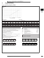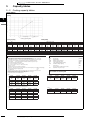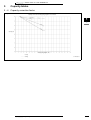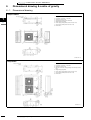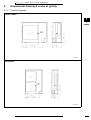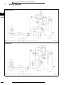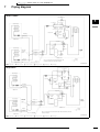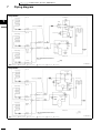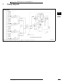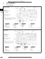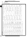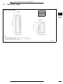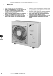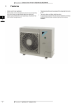
1
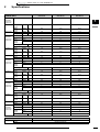
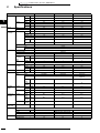
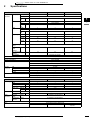
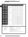
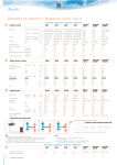
• Outdoor Units • R-410A • RZQS-B7V3
1
A i ny Uk 3 S Vr 7 o BAt o0- i dS1 l Qt4 pZu- R•OS
•
1
Outdoor units for pair, twin, triple, double twin application
The Sky Air Inverter is developed for use in shops, restaurants and
small offices. This innovative Daikin unit provides a more
comfortable environment and offers great savings in energy
consumption to shop and office owners.
•
During start up, the room can be cooled down or heated very quickly.
Once the temperature in the room has reached its set point, the low
power operation starts to save energy.
•
Daikin outdoor units are neat and sturdy and can be mounted easily
on a roof or terrace or simply placed against an outside wall.
•
The use of inverter type outdoor units results in an air conditioning
system with a high energy efficiency and very low sound level
•
Outdoor units are fitted with either a swing or scroll compressor,
renowned for low noise and high energy efficiency
•
An inverter driven compressor allows the capacity to be adjusted
precisely to match variations in room and outside temperatures.
•
A special acryl precoated fin for anti-corrosion treatment on the heat
exchanger ensures greater resistance against severe weather
conditions.
1
1
Features
• Split Sky Air • Outdoor Units
• Outdoor Units • R-410A • RZQS-B7V3
2
Specifications
2-1 NOMINAL CAPACITY AND
NOMINAL INPUT
For
combination
indoor units +
outdoor units
Condition 2
Nominal input
For
combination
indoor units +
outdoor units
Condition 2
Nominal input
For
combination
indoor units +
outdoor units
Condition 2
Nominal input
For
combination
indoor units +
outdoor units
Condition 2
Nominal input
For
combination
indoor units +
outdoor units
2-2
Casing
Indoor Units
R ZQS7 1B7V3B
RZQS100B7 V3 B
RZQS125B7V3B
FCQ71B7V3B
FCQ100B7V3B
FCQ125B7V3B
3
1
Cooling
Standard
capacity
Heating
Standard
capacity
Cooling
Standard
Heating
Standard
EER
Nominal
COP
Nominal
Energy
Cooling
Labeling
Heating
Directive
Annual energy consumption
Indoor Units
Cooling
Standard
capacity
Heating
Standard
capacity
Cooling
Standard
Heating
Standard
EER
Nominal
COP
Nominal
Energy
Cooling
Labeling
Heating
Directive
Annual energy consumption
Indoor Units
Cooling
Standard
capacity
Heating
Standard
capacity
Cooling
Standard
Heating
Standard
EER
Nominal
COP
Nominal
Energy
Cooling
Labeling
Heating
Directive
Annual energy consumption
Indoor Units
Cooling
Standard
capacity
Heating
Standard
capacity
Cooling
Standard
Heating
Standard
EER
Nominal
COP
Nominal
Energy
Cooling
Labeling
Heating
Directive
Annual energy consumption
kW
7.10
10.00
12.50
kW
8.00
11.20
14.00
kW
kW
2.46
2.61
2.89
3.07
C
D
3.83
3.47
2.61
3.23
D
C
4.14
4.52
3.02
3.10
B
D
kWh
kW
1230
FBQ71B7V3B
7.10
1915
FBQ100B7V3B
10.00
2070
FBQ125B7V3B
12.50
kW
8.00
11.20
14.00
kW
kW
2.52
2.40
2.82
3.33
C
3.83
3.47
2.61
3.23
D
C
4.40
4.24
2.84
3.30
C
kWh
kW
1260
FHQ71BUV1B
7.10
1915
FHQ100BUV1B
10.00
2200
FHQ125BUV1B
12.50
kW
8.00
11.20
14.00
kW
kW
2.53
2.84
2.81
2.82
C
4.15
3.99
2.41
2.81
E
D
4.58
4.96
2.73
2.82
D
kWh
kW
1265
FAQ71BUV1B
7.10
2075
FAQ100BUV1B
10.00
2290
FDQ125B7V3B
12.50
kW
8.00
11.20
14.00
kW
kW
2.53
2.61
2.81
3.01
C
D
4.08
3.73
2.45
3.00
E
D
4.45
4.08
2.81
3.43
C
B
kWh
1265
2040
2225
R ZQS7 1B7V3B
RZQS100B7 V3 B
RZQS125B7V3B
TECHNICAL SPECIFICATIONS
Colour
Material
2
Ivory W hite
Painted galvanised steel
• Split Sky Air • Outdoor Units
2
• Outdoor Units • R-410A • RZQS-B7V3
2
Specifications
2-2 TECHNICAL SPECIFICATIONS
Dimensions
1
Unit
Packing
2
Weight
Heat
Exchanger
Unit
Packed Unit
Dimensions
Tube type
Fin
Fan
Motor
Fan
Compressor
Operation
Range
Cooling
Cooling
Heating
Sound Level
(Night quiet)
Refr iger ant
Refr iger ant Oil
3
mm
mm
mm
mm
mm
mm
kg
kg
mm
Length
Nr of Rows
Fin Pitch mm
Nr of Passes
Face
m²
Area
Nr of Stages
Sound Pr essur e
Type
Char ge
Control
Nr of Circuits
Type
Char ged Volume
RZQS71B7V3B
RZQS100B 7V3B
RZQS125B7 V3 B
770
900
320
900
980
420
68
72
857
2
1.40
3
0.641
770
900
320
900
980
420
68
72
857
2
1.40
3
0.641
1345
900
320
1475
980
420
106
111
857
2
1.40
5
1.131
34
34
Hi- XSS(8)
W F fin
Anti-corrosion treatment (PE)
Propeller
Horizontal
1
61.3
61.7
60
Type
Tr eatment
Type
Dischar ge direction
Quantity
Air Flow Rate Cooling
(nominal at
Heating
230V)
Motor
Quantity
Model
Speed
Steps
(nominal)
Cooling
Heating
Motor
Output
Quantity
Motor
Model
Type
Heating
Sound Level
(nominal)
Height
W idth
Depth
Height
W idth
Depth
Motor
Output
Crankcas
e Heater
Min
Max
Min
Max
Sound
Power
Sound
Pressure
Sound
Pressure
m³/min
m³/min
rpm
rpm
W
W
1
54.5
48.1
1
KFD-325-70-8A
8
8
818
920
715
920
70
70
1
1
2YC63BXD
2YC63BXD
Her metically sealed swing compressor
2
99.0
100.0
1
2
1800
8
782
767
70
1
JT100G-VD
Hermetically sealed scroll
compressor
2200
1800
W
33
°CDB
°CDB
°CWB
°CWB
dBA
- 5.0
46.0
-15.0
15.5
65.0
-5.0
46.0
- 15.0
15.5
67.0
-5.0
46.0
-15.0
15.5
67.0
dBA
49.0
51.0
51.0
dBA
51.0
55.0
53.0
dBA
43.0
45.0
45.0
kg
2.80
l
1
Daphne FVC50K
0.8
• Split Sky Air • Outdoor Units
R-410A
2.80
Expansion valve ( electr onic type)
1
Daphne FVC50K
0.8
4.3
1
Daphne FVC68D
1.0
• Outdoor Units • R-410A • RZQS-B7V3
2
2-2
Specifications
TECHNICAL SPECIFICATIONS
Piping
connections
Liquid ( OD)
Quantity
Type
Diameter
(OD)
Gas
Quantity
Type
Diameter
(OD)
Drain
Quantity
Type
Diameter
(OD)
Piping Length Minimum
Maximum
Equivalen
t
Chargele
ss
Additional Refrigerant
Charge
Installation
Maximum
height
difference
Max. internunit level
difference
Heat Insulation
mm
mm
9.52
15.9
1
Flare connection
15.9
9.52
1
26
m
m
m
5
30
40
5
50
70
5
50
70
m
30
30
30
kg/m
1
2
3
26
see installation manual 4PW32097-1
m
15
30
30
m
0.5
0.5
0.5
Hz
V
Minimum V
Maximum V
Cur rent
Z-max
List
Recomended fuses
A
Wiring
For Power
Remark
connections
Supply
For connection Remark
with indoor
Power Supply Intake
Notes
3
15.9
mm
Item
Quantity
Item
Quantity
Name
Phase
Frequency
Voltage
Voltage range
1
3
Hole
26
ELECTRICAL SPECIFICATIONS
Power Supply
RZQS125B7V3B
1
Flare connection
9.52
3
Notes
2-3
RZQS100B7 V3 B
1
1
Defrost Method
Defrost Control
Capacity Control Method
Safety Devices
Standard
Accessories
R ZQS7 1B7V3B
Both liquid and gas pipes
Pressur e equalising
Sensor for outdoor heat exchanger temperature
Inverter controlled
High pressure switch
Fan motor thermal protector
Fuse
Tie- wr aps
2
2
2
Installation manual
1
1
1
Nominal cooling capacities are based on : indoor temperature : 27°CDB, 19°CWB, outdoor temperatur e : 35°CDB
Nominal heating capacities are based on : indoor temperature : 20°CDB, outdoor temperature : 7°CDB, 6°CWB
R ZQS7 1B7V3B
1
50
230
20
RZQS100B7 V3 B
V3
1
50
230
-10%
+10%
Complies to EN6100-3-3
20
see installation manual 4PW32097-1
RZQS125B7V3B
1
50
230
32
see installation manual 4PW32097-1
Outdoor unit only
See separate drawings for electrical data
Power supply to the FDQ indoor unit
is separate
• Split Sky Air • Outdoor Units
4
• Outdoor Units • R-410A • RZQS-B7V3
3
Electrical data
RZQ71-125BV3
Unit combination
Indoor unit
Outdoor unit
1
FCQ71BV3
FCQ35BV3x2
FFQ35BV3x2
FBQ71BV3
FBQ35BV3x2
FHQ71BV3
FHQ35BV3x2
FAQ71BV3
FCQ100BV3
FCQ50BV3x2
FCQ35BV3x3
FFQ50BV3x2
FFQ35BV3x3
FBQ100BV3
FBQ50BV3x2
FBQ35BV3x3
FHQ100BV3
FHQ50BV3x2
FHQ35BV3x3
FAQ100BV3
FCQ125BV3
FCQ60BV3x2
FCQ50BV3x3
FCQ35BV3x4
FFQ60BV3x2
FFQ50BV3x3
FFQ35BV3x4
FBQ125BV3
FBQ60BV3x2
FBQ50BV3x3
FBQ35BV3x4
FHQ125BV3
FHQ60BV3x2
FHQ50BV3x3
FHQ35BV3x4
FDQ125BV3
3
Power supply
Voltage range
MCA
Hz-volts
RZQS71BV3
RZQS71BV3
RZQS71BV3
RZQS71BV3
RZQS71BV3
RZQS71BV3
RZQS71BV3
RZQS71BV3
RZQS100BV3
RZQS100BV3
RZQS100BV3
RZQS100BV3
RZQS100BV3
RZQS100BV3
RZQS100BV3
RZQS100BV3
RZQS100BV3
RZQS100BV3
RZQS100BV3
RZQS100BV3
RZQS125BV3
RZQS125BV3
RZQS125BV3
RZQS125BV3
RZQS125BV3
RZQS125BV3
RZQS125BV3
RZQS125BV3
RZQS125BV3
RZQS125BV3
RZQS125BV3
RZQS125BV3
RZQS125BV3
RZQS125BV3
RZQS125BV3
RZQS125BV3
TOCA
MFA
Comp.
MSC
RLA
OFM
kW
IFM
FLA
kW
FLA
Max. 50Hz253V
Min. 50Hz207V
Max. 50Hz253V
Min. 50Hz207V
Max. 50Hz253V
Min. 50Hz207V
3D055645
SYMBOLS
MCA
TOCA
MFA
MSC
RLA
OFM
IFM
FLA
kW
NOTES
: Min. Circuit Amps (A)
: Total Over Current Amps (A)
: Max. Fuse Amps (See note 7) (A)
: MSC means the max. current during the
starting of compressor. (A)
: Rated Load Amps (A)
: Outdoor Fan Motor (A)
: Indoor Fan Motor
: Full Load Amps
: Fan Motor Rated Output (kW)
1
2
3
4
5
6
7
8
5
RLA is based on the following conditions:
Power supply: 50Hz 230V
Cooling
Heating
Indoor temperature 27°CDB/19°CWB
Indoor temperature 20.0°CDB
Outdoor temperature 35°CDB
Outdoor temperature 7.0°CDB/6.0°CWB
TOCA means the total value of each OC set
Voltage range
Units are suitable for use on electrical systems where voltage supplied to unit terminals is not below or
above listed operation range limits
Maximum allowable voltage unbalance between phases is 2%
MCA represents maximum input current., MFA represents capacity which may accept MCA
(next lower standard fuse rating, min.15A)
Select wire size based on the larger value of MCA or TOCA
MFA is used to select the circuit breaker and the ground fault circuit interrupter (earth leakage circuit breaker)
For more details concerning conditional connections, see http://extranet.daikineurope.com, select ’’E-Data Books’’. Finally, click on the
document title of your choice.
• Split Sky Air • Outdoor Units
• Outdoor Units • R-410A • RZQS-B7V3
4
Options
3
Available option for RZQS71-125BV3
Kit name
Name of option
RZQS71B7V3B
Central drain plug
Refrigerant branch piping
RZQS100B7V3B
RZQS125B7V3B
KKPJ5F180
Twin
4
KHRQ22M20TA
Triple
-
Double twin
-
Demand adapter kit
1
KHRQ127H
-
KHRQ22M20TA (3x)
KRP58M51
3TW26739-1C
• Split Sky Air • Outdoor Units
6
• Outdoor Units • R-410A • RZQS-B7V3
5
Capacity tables
5-1
Combination table
Possible combinations and standard capacity for twin, triple and double twin application
Possible indoor combination
1
Simultaneous operation
5
Outdoor models
Twin
Triple
Out
Out
In
In
In
In
RZQS71BV3
35-35
(KHRQ22M20TA7)
RZQS100BV3
50-50
(KHRQ22M20TA7)
35-35-35
(KHRQ127H7)
RZQS125BV3
60-60
(KHRQ22M20TA7)
50-50-50
(KHRQ127H7)
Double twin
Out
In
In
In
In
In
35-35-35-35
(3x KHRQ22M20TA7)
3TW29069-1
NOTES
7
1
Possible indoor units: FCQ35-125B, FFQ35-60BV, FHQ35-125B, FBQ35-125B, FAQ71-100B, FDQ125B
2
Individual indoor capacities are not given because the combinations are for simultaneous operation (=indoor units installed in same room).
3
When different indoor models are used in combination, designate the infrared remote controller that is equipped with the most functions as the
main unit.
In note 1 are the indoor units mentioned in order of the possible function (most functions are on FCQ, less functions are on FAQ).
4
Between brackets are the required Refnet kits mentioned, that are necessary to install the combination.
• Split Sky Air • Outdoor Units
• Outdoor Units • R-410A • RZQS-B7V3
5
Capacity tables
5-2
Cooling capacity tables
3
RZQS71BV3
Cooling
Coefficient of power input. (-)
1
5
Capacity range
Rated point
Cooling capacity (kW)
Cooling capacity
230V [50Hz]
Indoor
EWB
Outdoor temp. (°CDB)
EDB
(°C)
(°C)
16.0
18.0
19.0
19.5
22.0
24.0
22
25
27
27
30
32
TC
(kW)
6.47
7.43
7.58
7.66
8.05
8.37
25
SHC
(kW)
4.39
4.82
4.80
4.79
4.73
4.66
CPI
(-)
0.76
0.83
0.84
0.84
0.85
0.85
TC
(kW)
6.46
7.20
7.35
7.43
7.81
8.12
30
SHC
(kW)
4.43
4.72
4.71
4.70
4.64
4.58
CPI
(-)
0.89
0.91
0.91
0.91
0.92
0.93
TC
(kW)
6.66
6.95
7.10
7.17
7.55
7.85
35
SHC
(kW)
4.62
4.61
4.60
4.59
4.54
4.48
CPI
(-)
0.99
1.00
1.00
1.00
1.01
1.02
TC
(kW)
6.39
6.67
6.82
6.89
7.26
7.55
40
SHC
(kW)
4.49
4.47
4.46
4.46
4.41
4.35
CPI
(-)
1.09
1.10
1.10
1.10
1.11
1.12
3D055646
NOTES
SYMBOLS
1. Ratings shown are net capacities which include a deduction for indoor fan motor heat
2. On the figure the mark j show the max. at standard conditions.
On the figure the mark Q show rated capacity and rated coefficient of power input.
However the max. capacity is not guaranteed, except at standard condition.
3. On the tables Q show rated capacity and rated coefficient of power input.
4. SHC is based on each EWB and EDB
SHC* = SHC correction for other dry bulb
SHC* = 0.02 x AFR (m3/min.) x (1−BF) x (DB*−EDB)
Add SHC* to SHC.
5. Capacities are based on following conditions:
Outdoor air : 85 % RH. however, the condition on nominal capacity is 7° CDB/6° CWB
(heating)
Corresponding refrigerant piping length
: 7.5 m
Level difference
:0m
6. Coefficient of power input is the percentage when the rated valve is defined as 1.00.
7. The value contains less than 5% error acording to indoor unit type.
8. Heating capacity include the drop of frost formation.
9. Air flow rate and BF are tabulated below.
(Pair)
Model
AFR
(BF)
FCQ71B
18
(0.10)
FBQ71B
19
(0.11)
FHQ71B
17
(0.10)
FAQ71B
19
(0.08)
10. Rated power input of each model is tabulated below.
(Pair)
Model
Cooling
Heating
FCQ71B
2.46
2.61
FBQ71B
2.52
2.40
FHQ71B
2.53
2.85
FAQ71B
2.53
2.61
• Split Sky Air • Outdoor Units
AFR:
BF:
EWB:
EDB:
TC:
SHC:
PI:
CPI:
(m3/min)
Air flow rate
Bypass factor
Entering wet bulb temp.
Entering dry bulb temp.
Total cooling/heating capacity
Sensible heating capacity
Power input
(comp.+indoor+outdoor fan motor)
Coefficient of power input.
(°CWB)
(°CDB)
(kW)
(kW)
(kW)
(-)
Caution:
TC and SHC are shown by kW
(Multi)
Model
AFR
(BF)
FCQ35Bx2
14x2
(0.16x2)
FFQ35Bx2
10x2
(0.25x2)
FBQ35Bx2
11.5x2
(0.15x2)
FHQ35Bx2
13x2
(0.2x2)
FCQ35Bx2
2.59
2.75
FFQ35Bx2
2.61
2.70
FBQ35Bx2
2.57
2.47
FHQ35Bx2
2.66
2.85
(Multi)
Model
Cooling
Heating
8
• Outdoor Units • R-410A • RZQS-B7V3
5
Capacity tables
5-2
Cooling capacity tables
RZQS100BV3
1
5
Coefficient of power input. (-)
Cooling
Capacity range
Rated point
Cooling capacity (kW)
Cooling capacity
400V [50Hz]
Indoor
Outdoor temp. (°CDB)
EWB
EDB
(°C)
(°C)
16.0
18.0
19.0
19.5
22.0
24.0
22
25
27
27
30
32
TC
(kW)
9.12
10.5
10.7
10.8
11.3
11.8
25
SHC
(kW)
6.19
6.78
6.76
6.75
6.66
6.57
CPI
(-)
0.76
0.83
0.84
0.84
0.85
0.85
TC
(kW)
9.10
10.1
10.4
10.5
11.0
11.4
30
SHC
(kW)
6.25
6.65
6.63
6.62
6.54
6.45
CPI
(-)
0.89
0.91
0.91
0.91
0.92
0.93
TC
(kW)
9.38
9.79
10.0
10.1
10.6
11.1
35
SHC
(kW)
6.51
6.49
6.48
6.47
6.39
6.30
CPI
(-)
0.99
1.00
1.00
1.00
1.01
1.02
TC
(kW)
9.00
9.40
9.60
9.71
10.2
10.6
40
SHC
(kW)
6.32
6.30
6.29
6.28
6.21
6.13
CPI
(-)
1.09
1.10
1.10
1.10
1.11
1.12
3D055647
NOTES
SYMBOLS
1. Ratings shown are net capacities which include a deduction for indoor fan motor heat
2. On the figure the mark j show the max. at standard conditions.
On the figure the mark Q show rated capacity and rated coefficient of power input.
However the max. capacity is not guaranteed, except at standard condition.
3. On the tables Q show rated capacity and rated coefficient of power input.
4. SHC is based on each EWB and EDB
SHC* = SHC correction for other dry bulb
3
SHC* = 0.02 x AFR (m /min.) x (1−BF) x (DB*−EDB)
Add SHC* to SHC.
5. Capacities are based on following conditions:
Outdoor air : 85 % RH. however, the condition on nominal capacity is 7° CDB/6° CWB (heating)
Corresponding refrigerant piping length
: 7.5 m
Level difference
:0m
6. Coefficient of power input is the percentage when the rated valve is defined as 1.00.
7. The value contains less than 5% error acording to indoor unit type.
8. Heating capacity include the drop of frost formation.
9. Air flow rate and BF are tabulated below.
(Pair)
AFR:
BF:
EWB:
EDB:
TC:
SHC:
PI:
CPI:
(m3/min)
Air flow rate
Bypass factor
Entering wet bulb temp.
Entering dry bulb temp.
Total cooling/heating capacity
Sensible heating capacity
Power input
(comp.+indoor+outdoor fan motor)
Coefficient of power input.
(°CWB)
(°CDB)
(kW)
(kW)
(kW)
(-)
Caution:
TC and SHC are shown by kW
(Twin)
Model
AFR
(BF)
FCQ100B
28
(0.16)
FBQ100B
27
(0.20)
FHQ100B
24
(0.14)
FAQ100B
23
(0.10)
Model
AFR
(BF)
FCQ50Bx2
14x3
(0.16x3)
FFQ50Bx2
10x3
(0.25x3)
FBQ50Bx2
11.5x3
(0.15x3)
FHQ50Bx2
13x3
(0.2x3)
Model
AFR
(BF)
FCQ35Bx3
15x2
(0.16x2)
FFQ35Bx3
12x2
(0.16x2)
FBQ35Bx3
14x2
(0.15x2)
FHQ35Bx3
13x2
(0.1x2)
FCQ50Bx2
3.83
3.65
FFQ50Bx2
3.83
3.54
FBQ50Bx2
3.83
3.58
FHQ50Bx2
4.15
3.99
(Triple)
10. Rated power input of each model is tabulated below.
(Pair)
Model
Cooling
Heating
(Twin)
FCQ100B
3.83
3.47
FBQ100B
3.83
3.47
FHQ100B
4.15
3.99
FAQ100B
4.08
3.73
FCQ35Bx3
3.83
3.65
FFQ35Bx3
3.83
3.54
FBQ35Bx3
3.83
3.58
FHQ35Bx3
4.15
3.99
(Triple)
Model
Cooling
Heating
9
• Split Sky Air • Outdoor Units
Model
Cooling
Heating
• Outdoor Units • R-410A • RZQS-B7V3
5
Capacity tables
5-2
Cooling capacity tables
3
RZQS125BV3
Cooling
Coefficient of power input. (-)
1
5
Rated point
Capacity range
Cooling capacity (kW)
Cooling capacity
400V [50Hz]
Indoor
Outdoor temp. (°CDB)
EWB
EDB
(°C)
(°C)
16.0
18.0
19.0
19.5
22.0
24.0
22
25
27
27
30
32
TC
(kW)
11.4
13.1
13.3
13.5
14.2
14.7
25
SHC
(kW)
7.73
8.48
8.45
8.44
8.33
8.21
CPI
(-)
0.76
0.83
0.84
0.84
0.85
0.85
TC
(kW)
11.4
12.7
12.9
13.1
13.8
14.3
30
SHC
(kW)
7.81
8.32
8.29
8.28
8.18
8.06
CPI
(-)
0.89
0.91
0.91
0.91
0.92
0.93
TC
(kW)
11.7
12.2
12.5
12.6
13.3
13.8
35
SHC
(kW)
8.14
8.12
8.09
8.08
7.99
7.88
CPI
(-)
0.99
1.00
1.00
1.00
1.01
1.02
40
SHC
(kW)
7.90
7.88
7.86
7.85
7.76
7.67
TC
(kW)
11.3
11.8
12.0
12.1
12.8
13.3
CPI
(-)
1.09
1.10
1.10
1.10
1.11
1.12
3D055649A
NOTES
SYMBOLS
1. Ratings shown are net capacities which include a deduction for indoor fan motor heat
2. On the figure the mark j show the max. at standard conditions.
On the figure the mark Q show rated capacity and rated coefficient of power input.
However the max. capacity is not guaranteed, except at standard condition.
3. On the tables Q show rated capacity and rated coefficient of power input.
4. SHC is based on each EWB and EDB
SHC* = SHC correction for other dry bulb
3
SHC* = 0.02 x AFR (m /min.) x (1−BF) x (DB*−EDB)
Add SHC* to SHC.
5. Capacities are based on following conditions:
Outdoor air : 85 % RH. however, the condition on nominal capacity is 7° CDB/6° CWB (heating)
Corresponding refrigerant piping length
: 7.5 m
Level difference
:0m
6. Coefficient of power input is the percentage when the rated valve is defined as 1.00.
7. The value contains less than 5% error acording to indoor unit type.
8. Heating capacity include the drop of frost formation.
9. Air flow rate and BF are tabulated below.
AFR:
BF:
EWB:
EDB:
TC:
SHC:
PI:
CPI:
(m3/min)
Air flow rate
Bypass factor
Entering wet bulb temp.
Entering dry bulb temp.
Total cooling/heating capacity
Sensible heating capacity
Power input
(comp.+indoor+outdoor fan motor)
Coefficient of power input.
(°CWB)
(°CDB)
(kW)
(kW)
(kW)
(-)
Caution:
TC and SHC are shown by kW
(Twin)
(Pair)
Model
AFR
(BF)
FCQ125B
31
(0.07)
FBQ125B
35
(0.14)
FHQ125B
30
(0.13)
FDQ125B
45
(0.25)
FCQ50Bx3
15x3
(0.16x3)
FFQ50Bx3
12x3
(0.16x3)
FBQ50Bx3
14x3
(0.15x3)
FHQ50Bx3
13x3
(0.1x3)
10. Rated power input of each model is tabulated below.
(Pair)
Model
Cooling
Heating
FFQ60Bx2
15x2
(0.11x2)
FBQ60Bx2
19x2
(0.11x2)
FHQ60Bx2
17x2
(0.2x2)
Model
AFR
(BF)
FCQ35Bx4
14x4
(0.16x4)
FFQ35Bx4
10x4
(0.25x4)
FBQ35Bx4
11.5x4
(0.15x4)
FHQ35Bx4
13x4
(0.2x4)
FCQ60Bx2
4.36
4.76
FFQ60Bx2
4.41
4.42
FBQ60Bx2
4.48
4.42
FHQ60Bx2
4.76
4.92
FCQ35Bx4
4.36
4.76
FFQ35Bx4
4.41
4.42
FBQ35Bx4
4.48
4.42
FHQ35Bx4
4.76
4.92
(Twin)
FCQ125B
4.14
4.52
FBQ125B
4.40
4.24
FHQ125B
4.58
4.96
FDQ125B
4.45
4.08
FCQ50Bx3
4.36
4.76
FFQ50Bx3
4.41
4.42
FBQ50Bx3
4.48
4.42
FHQ50Bx3
4.76
4.92
(Triple)
Model
Cooling
Heating
FCQ60Bx2
18x2
(0.1x2)
(Double twin)
(Triple)
Model
AFR
(BF)
Model
AFR
(BF)
Model
Cooling
Heating
(Double twin)
• Split Sky Air • Outdoor Units
Model
Cooling
Heating
10
• Outdoor Units • R-410A • RZQS-B7V3
5
Capacity tables
5-3
Heating capacity tables
RZQS71BV3
1
5
Coefficient of power input. (-)
Heating
Rated point
Capacity range
Heating capacity (kW)
Heating capacity
Indoor
EDB
TC
(kW)
5.68
5.67
5.67
5.66
5.66
5.65
(°C)
16.O
18.O
20.0
21.O
22.O
24.0
230V [50Hz]
−10
CPI
(-)
1.12
1.16
1.21
1.23
1.25
1.30
TC
(kW)
6.22
6.21
6.20
6.20
6.19
6.19
−5
CPI
(-)
1.17
1.22
1.27
1.29
1.32
1.36
Outdoor temp. (°CWB)
0
TC
CPI
(kW)
(-)
6.75
1.23
6.74
1.28
6.74
1.33
6.73
1.35
6.73
1.38
6.72
1.43
6
TC
(kW)
8.02
8.01
8.00
8.00
7.99
7.98
10
CPI
(-)
0.92
0.96
1.00
1.02
1.04
1.08
TC
(kW)
8.64
8.62
8.61
8.61
8.60
8.59
CPI
(-)
0.97
1.01
1.05
1.07
1.09
1.13
3D055646
NOTES
SYMBOLS
1. Ratings shown are net capacities which include a deduction for indoor fan
motor heat
2. On the figure the mark j show the max. at standard conditions.
On the figure the mark Q show rated capacity and rated coefficient of
power input.
However the max. capacity is not guaranteed, except at standard condition.
3. On the tables Q show rated capacity and rated coefficient of power input.
4. SHC is based on each EWB and EDB
SHC* = SHC correction for other dry bulb
SHC* = 0.02 x AFR (m3/min.) x (1−BF) x (DB*−EDB)
Add SHC* to SHC.
5. Capacities are based on following conditions:
Outdoor air : 85 % RH. however, the condition on nominal capacity is
7° CDB/6° CWB (heating)
Corresponding refrigerant piping length
: 7.5 m
Level difference
:0m
6. Coefficient of power input is the percentage when the rated valve is defined
as 1.00.
7. The value contains less than 5% error acording to indoor unit type.
8. Heating capacity include the drop of frost formation.
9. Air flow rate and BF are tabulated below.
(Pair)
Model
AFR
(BF)
FCQ71B
18
(0.10)
FBQ71B
19
(0.11)
FHQ71B
17
(0.10)
FAQ71B
19
(0.08)
10. Rated power input of each model is tabulated below.
(Pair)
Model
Cooling
Heating
11
FCQ71B
2.46
2.61
FBQ71B
2.52
2.40
FHQ71B
2.53
2.85
FAQ71B
2.53
2.61
• Split Sky Air • Outdoor Units
AFR:
BF:
EWB:
EDB:
TC:
SHC:
PI:
Air flow rate
Bypass factor
Entering wet bulb temp.
Entering dry bulb temp.
Total cooling/heating capacity
Sensible heating capacity
Power input
(comp.+indoor+outdoor fan motor)
Coefficient of power input.
CPI:
(m3/min)
(°CWB)
(°CDB)
(kW)
(kW)
(kW)
(-)
Caution:
TC and SHC are shown by kW
(Multi)
Model
AFR
(BF)
FCQ35Bx2
14x2
(0.16x2)
FFQ35Bx2
10x2
(0.25x2)
FBQ35Bx2
11.5x2
(0.15x2)
FHQ35Bx2
13x2
(0.2x2)
FCQ35Bx2
2.59
2.75
FFQ35Bx2
2.61
2.70
FBQ35Bx2
2.57
2.47
FHQ35Bx2
2.66
2.85
(Multi)
Model
Cooling
Heating
• Outdoor Units • R-410A • RZQS-B7V3
5
Capacity tables
5-3
Heating capacity tables
3
RZQS100BV3
Heating
Coefficient of power input. (-)
1
5
Capacity range
Rated point
Heating capacity (kW)
Heating capacity
400V [50Hz]
Indoor
EDB
−10
TC
(kW)
7.91
7.90
7.89
7.89
7.88
7.87
(°C)
16.O
18.O
20.0
21.O
22.O
24.0
CPI
(-)
1.07
1.11
1.15
1.17
1.20
1.24
TC
(kW)
8.66
8.65
8.64
8.63
8.63
8.62
−5
Outdoor temp. (°CWB)
0
TC
CPI
(kW)
(-)
9.41
1.17
9.39
1.22
9.38
1.27
9.38
1.29
9.37
1.32
9.36
1.36
CPI
(-)
1.12
1.16
1.21
1.23
1.26
1.30
6
TC
(kW)
11.2
11.2
11.2
11.2
11.2
11.2
10
CPI
(-)
0.92
0.96
1.00
1.02
1.04
1.08
TC
(kW)
12.1
12.1
12.1
12.1
12.0
12.0
CPI
(-)
0.97
1.01
1.05
1.07
1.09
1.13
3D055647
NOTES
SYMBOLS
1. Ratings shown are net capacities which include a deduction for indoor fan motor heat
2. On the figure the mark j show the max. at standard conditions.
On the figure the mark Q show rated capacity and rated coefficient of power input.
However the max. capacity is not guaranteed, except at standard condition.
3. On the tables Q show rated capacity and rated coefficient of power input.
4. SHC is based on each EWB and EDB
SHC* = SHC correction for other dry bulb
3
SHC* = 0.02 x AFR (m /min.) x (1−BF) x (DB*−EDB)
Add SHC* to SHC.
5. Capacities are based on following conditions:
Outdoor air : 85 % RH. however, the condition on nominal capacity is 7° CDB/6° CWB (heating)
Corresponding refrigerant piping length
: 7.5 m
Level difference
:0m
6. Coefficient of power input is the percentage when the rated valve is defined as 1.00.
7. The value contains less than 5% error acording to indoor unit type.
8. Heating capacity include the drop of frost formation.
9. Air flow rate and BF are tabulated below.
AFR:
BF:
EWB:
EDB:
TC:
SHC:
PI:
(m3/min)
Air flow rate
Bypass factor
Entering wet bulb temp.
Entering dry bulb temp.
Total cooling/heating capacity
Sensible heating capacity
Power input
(comp.+indoor+outdoor fan motor)
Coefficient of power input.
CPI:
(°CWB)
(°CDB)
(kW)
(kW)
(kW)
(-)
Caution:
TC and SHC are shown by kW
(Twin)
(Pair)
Model
AFR
(BF)
FCQ100B
28
(0.16)
FBQ100B
27
(0.20)
FHQ100B
24
(0.14)
FAQ100B
23
(0.10)
Model
AFR
(BF)
FCQ35Bx3
14x3
(0.16x3)
FFQ35Bx3
10x3
(0.25x3)
FBQ35Bx3
11.5x3
(0.15x3)
FHQ35Bx3
13x3
(0.2x3)
Model
AFR
(BF)
FCQ50Bx2
15x2
(0.16x2)
FFQ50Bx2
12x2
(0.16x2)
FBQ50Bx2
14x2
(0.15x2)
FHQ50Bx2
13x2
(0.1x2)
FCQ50Bx2
3.83
3.65
FFQ50Bx2
3.83
3.54
FBQ50Bx2
3.83
3.58
FHQ50Bx2
4.15
3.99
(Triple)
10. Rated power input of each model is tabulated below.
(Pair)
Model
Cooling
Heating
(Twin)
FCQ100B
3.83
3.47
FBQ100B
3.83
3.47
FHQ100B
4.15
3.99
FAQ100B
4.08
3.73
FCQ35Bx3
3.83
3.65
FFQ35Bx3
3.83
3.54
FBQ35Bx3
3.83
3.58
FHQ35Bx3
4.15
3.99
Model
Cooling
Heating
(Triple)
Model
Cooling
Heating
• Split Sky Air • Outdoor Units
12
• Outdoor Units • R-410A • RZQS-B7V3
5
Capacity tables
5-3
Heating capacity tables
RZQS125BV3
1
5
Coefficient of power input. (-)
Heating
Capacity range
Rated point
Heating capacity (kW)
Heating capacity
Indoor
EDB
TC
(kW)
9.76
9.74
9.73
9.73
9.72
9.71
(°C)
16.O
18.O
20.0
21.O
22.O
24.0
230V [50Hz]
−10
CPI
(-)
1.11
1.15
1.20
1.22
1.24
1.29
TC
(kW)
10.7
10.7
10.7
10.6
10.6
10.6
−5
CPI
(-)
1.16
1.21
1.26
1.28
1.31
1.35
Outdoor temp. (°CWB)
0
TC
CPI
(kW)
(-)
11.6
1.22
11.6
1.27
11.6
1.32
11.6
1.34
11.6
1.37
11.5
1.42
6
TC
(kW)
14.0
14.0
14.0
14.0
14.0
14.0
10
CPI
(-)
0.92
0.96
1.00
1.02
1.04
1.08
TC
(kW)
15.1
15.1
15.1
15.1
15.1
15.0
CPI
(-)
0.97
1.01
1.05
1.07
1.09
1.13
3D0455649A
NOTES
SYMBOLS
1. Ratings shown are net capacities which include a deduction for indoor fan motor heat
2. On the figure the mark j show the max. at standard conditions.
On the figure the mark Q show rated capacity and rated coefficient of power input.
However the max. capacity is not guaranteed, except at standard condition.
3. On the tables Q show rated capacity and rated coefficient of power input.
4. SHC is based on each EWB and EDB
SHC* = SHC correction for other dry bulb
3
SHC* = 0.02 x AFR (m /min.) x (1−BF) x (DB*−EDB)
Add SHC* to SHC.
5. Capacities are based on following conditions:
Outdoor air : 85 % RH. however, the condition on nominal capacity is 7° CDB/6° CWB (heating)
Corresponding refrigerant piping length
: 7.5 m
Level difference
:0m
6. Coefficient of power input is the percentage when the rated valve is defined as 1.00.
7. The value contains less than 5% error acording to indoor unit type.
8. Heating capacity include the drop of frost formation.
9. Air flow rate and BF are tabulated below.
CPI:
(m3/min)
Air flow rate
Bypass factor
Entering wet bulb temp.
Entering dry bulb temp.
Total cooling/heating capacity
Sensible heating capacity
Power input
(comp.+indoor+outdoor fan motor)
Coefficient of power input.
(°CWB)
(°CDB)
(kW)
(kW)
(kW)
(-)
Caution:
TC and SHC are shown by kW
Triple
Pair
Model
AFR
(BF)
FCQ125B
31
(0.07)
FBQ125B
35
(0.14)
FHQ125B
30
(0.13)
FDQ125B
45
(0.25)
Model
AFR
(BF)
FCQ50Bx3
15x3
(0.16x3)
FFQ50Bx3
12x3
(0.16x3)
FBQ50Bx3
14x3
(0.15x3)
FHQ50Bx3
13x3
(0.1x3)
Model
AFR
(BF)
FCQ60Bx2
18x2
(0.1x2)
FFQ60Bx2
15x2
(0.11x2)
FBQ60Bx2
19x2
(0.11x2)
FHQ60Bx2
17x2
(0.2x2)
FCQ35Bx4
14x4
(0.16x4)
FFQ35Bx4
10x4
(0.25x4)
FBQ35Bx4
11.5x4
(0.15x4)
FHQ35Bx4
13x4
(0.2x4)
FCQ60Bx2
4.36
4.76
FFQ60Bx2
4.41
4.42
FBQ60Bx2
4.48
4.42
FHQ60Bx2
4.76
4.92
FCQ35Bx4
4.36
4.76
FFQ35Bx4
4.41
4.42
FBQ35Bx4
4.48
4.42
FHQ35Bx4
4.76
4.92
Double twin
Twin
10. Rated power input of each model is tabulated below.
Pair
Model
Cooling
Heating
Model
Cooling
Heating
Model
AFR
(BF)
Triple
FCQ125B
4.14
4.52
FBQ125B
4.40
4.24
FHQ125B
4.58
4.96
FDQ125B
4.45
4.08
FCQ50Bx3
4.36
4.76
FFQ50Bx3
4.41
4.42
FBQ50Bx3
4.48
4.42
FHQ50Bx3
4.76
4.92
Twin
13
AFR:
BF:
EWB:
EDB:
TC:
SHC:
PI:
Model
Cooling
Heating
Double twin
• Split Sky Air • Outdoor Units
Model
Cooling
Heating
• Outdoor Units • R-410A • RZQS-B7V3
5
Capacity tables
5-4
Capacity correction factor
RZQS71-125BV3
3
Capacity in function of field piping length for non-inverter
1
5
Capacity (%)
Field piping length (m)
Cooling
Heating
• Split Sky Air • Outdoor Units
3TW29069-3
14
• Outdoor Units • R-410A • RZQS-B7V3
6
Dimensional drawing & centre of gravity
6-1
Dimensional drawing
unit (mm)
RZQS71-100BV3
Hole for anchor bolt
4-M12
1
2
3
4
5
6
7
8
1
6
Gas pipe connection J15.9 flare
Liquid pipe connection - J9.5 flare
Service port (in the unit)
Grounding terminal M5 (in switch box)
Refrigerant piping intake
Power supply wiring intake (knock out hole J34)
Control wiring intake (Knock out hole J27)
Drain outlet
3TW25144-1A
unit (mm)
RZQS125BV3
Hole for anchor bolt
4-M12
1
2
3
4
5
6
7
8
Gas pipe connection J15.9 flare
Liquid pipe connection - J9.5 flare
Service port (in the unit)
Electronic connection and grounding terminal MS (in switch
box)
Refrigerant piping intake
Power supply wiring intake (knock out hole J34)
Control wiring intake (Knock out hole J27)
Drain outlet
3TW26071-1
15
• Split Sky Air • Outdoor Units
• Outdoor Units • R-410A • RZQS-B7V3
6
Dimensional drawing & centre of gravity
6-2
Centre of gravity
3
RZQS71-100BV3
1
6
4TW26069-3
RZQS125BV3
4TW26079-3
• Split Sky Air • Outdoor Units
16
• Outdoor Units • R-410A • RZQS-B7V3
7
Piping diagram
RZQS71-100BV3
Electronic expansion
valve
1
One way valve
One way valve
7
Heat exchanger
Filter
Service port
5/16″
One way valve
One way valve
Capillary tube
Solenoid valve
Receiver
Strainer
Heat exchanger
4-way valve
Muffler
Low pressure
sensor
Muffler
One way valve
Field piping J9.5 C1220T-0
Service port
5/16″
Filter
Field piping J15.9 C1220T-0
Compressor
High pressure
switch
Indoor unit
Outdoor unit
Heating
Cooling
Stop valve
(with service port 5/16’ flare)
O Check valve L Flare connection M Screw connection N Flange connection Z Pinched pipe P Spinned pipe
3TW26735-1
RZQS125BV3
One way valve
One way
valve
One way
valve
Heat exchanger
Filter
One way
valve
One way valve
Solenoid valve
Capillary tube
Capillary
tube
Receiver
Electronic
expansion
valve
Strainer
Capillary tube
Service port
5/16″
Heat exchanger
4-way valve
Filter
Low pressure
switch
High pressure
switch
Muffler
Field piping J9.5 C1220T-0
Service port
5/16″
Filter
Field piping J15.9 C1220T-0
Compressor
Indoor unit
Outdoor unit
Stop valve
(with service port 5/16’ flare)
O Check valve L Flare connection M Screw connection N Flange connection Z Pinched pipe P Spinned pipe
17
• Split Sky Air • Outdoor Units
Heating
Cooling
3TW26745-1
• Outdoor Units • R-410A • RZQS-B7V3
7
Piping diagram
3
RZQS71-100BV3
Electronic expansion
valve
One way valve
1
One way valve
Heat exchanger
7
Heat exchanger
Filter
Service port
5/16″
One way valve
One way valve
Capillary
tube
Solenoid valve
Field piping
Filter
Receiver
Field piping
Strainer
Indoor unit
4-way valve
Muffler
Low pressure
sensor
Muffler
Heat exchanger
One way valve
Branch duct
connection
Field piping J9.5
Service port
5/16″
Option
Field piping J15.9
Compressor
High pressure
switch
Outdoor unit
Field piping
Filter
Field piping
Stop valve
(with service port 5/16’ flare)
Indoor unit
Heating
Cooling
Note: 1. The pipes between the branch and the indoor units
should have the same size as the indoor connections.
3TW26735-2
O Check valve L Flare connection M Screw connection N Flange connection Z Pinched pipe P Spinned pipe
RZQS125BV3
One way valve
One way valve
One way
valve
One way valve
One way
valve
Heat exchanger
Filter
Solenoid valve
Capillary tube
Electronic
expansion valve
Capillary
tube
Strainer
Receiver
Field piping
Filter
Heat exchanger
Capillary tube
Field piping
Service port
5/16″
Indoor unit
4-way valve
Filter
Low pressure
switch
High pressure
switch
Muffler
Heat exchanger
Branch duct
connection
Service port
5/16″
Field piping J9.5
C1220T-0
Option
Field piping J15.9
Compressor
C1220T-0
Outdoor unit
Field piping
Filter
Indoor unit
Heating
Cooling
Field piping
Stop valve
(with service port 5/16’ flare)
Note: 1. The pipes between the branch and the indoor units should have the same size as
the indoor connections.
O Check valve L Flare connection M Screw connection N Flange connection Z Pinched pipe P Spinned pipe
• Split Sky Air • Outdoor Units
3TW26745-2
18
• Outdoor Units • R-410A • RZQS-B7V3
7
Piping diagram
RZQS100BV3
Indoor unit
Electronic expansion
valve
Heat exchanger
1
7
Stop valve
(with service port 5/16’ flare)
One way
valve
One way
valve
One way
valve
One way
valve
Filter
Service port
5/16″
Field piping
Filter
Heat exchanger
Capillary
tube
Field piping
Capillary tube
Solenoid valve
Indoor unit
Heat exchanger
Receiver
Strainer
Field piping J9.5
4-way valve
C1220T-0
Muffler
Field piping
Filter
Field piping
Low pressure
switch
Muffler
Field piping J15.9
C1220T-0
Service port
5/16″
Indoor unit
Heat exchanger
Branch duct
connection
(Option)
Compressor
High pressure
switch
Outdoor unit
Note: 1. The pipes between the branch and the
indoor units should have the same size as the indoor
connections.
Heating
Cooling
Field piping
Filter
Field piping
3TW29075-1
O Check valve L Flare connection M Screw connection N Flange connection Z Pinched pipe P Spinned pipe
RZQS125BV3
Indoor unit
Heat exchanger
One way valve
One way
valve
Stop valve
(with service port 5/16’ flare)
Filter
Heat exchanger
Filter
One way valve
Solenoid valve
Field piping
One way valve
One way valve
Capillary tube
Field piping
Capillary
tube
Indoor unit
Electronic
expansion valve
Receiver
Heat exchanger
Strainer
Capillary tube
Service port
5/16″
4-way valve
Field piping J9.5
C1220T-0
Field piping
Filter
Filter
Field piping
Low pressure
switch
High pressure
switch
Muffler
Field piping J15.9
Indoor unit
C1220T-0
Service port
5/16″
Heat exchanger
Branch duct
connection
Compressor
Option
Outdoor unit
Field piping
Filter
Field piping
Note: 1. The pipes between the branch and the
indoor units should have the same size as the indoor
connections.
O Check valve L Flare connection M Screw connection N Flange connection Z Pinched pipe P Spinned pipe
19
• Split Sky Air • Outdoor Units
Heating
Cooling
3TW26745-3
• Outdoor Units • R-410A • RZQS-B7V3
7
Piping diagram
3
RZQS125BV3
Heat exchanger
Indoor unit
1
One way valve
One way valve
7
One way valve
Field piping
Filter
Field piping
Heat exchanger
Indoor unit
Heat exchanger
One way valve
Filter
One way valve
Capillary tube
Field piping
J9.5
Solenoid valve
Electronic
expansion valve
Capillary tube
Receiver
Field piping
J15.9
4-way valve
Field piping
Heat
exchanger
Indoor unit
Capil ary tube
Service port
5/16″
Field piping
Filter
Strainer
Branch duct
connection
Field piping J9.5
Filter
Low pressure
High pressure switch
sensor
C1220T-0
Option
Service
port
5/16″
Field piping J15.9
Muffler
C1220T-0
Compressor
Field piping
Filter
Heat exchanger
Field piping
Outdoor unit
Heating
Cooling
Indoor unit
Field piping
J9.5
Field piping
J15.9
Stop valve
(with service port 5/16’ flare)
Field piping
Filter
Note: 1. The pipes between the branch and the indoor
units should have the same size as the indoor connections.
Field piping
O Check valve L Flare connection M Screw connection N Flange connection Z Pinched pipe P Spinned pipe
• Split Sky Air • Outdoor Units
3TW26755-4
20
• Outdoor Units • R-410A • RZQS-B7V3
8
Wiring diagram
8-1
Wiring diagram
RZQS71-100BV3
Indoor
L
N
: Live
: Neutral
: Field wiring
: Protective earth (screw)
: Wire clamp
: Terminal
: Connector
8
NOTE 1.
1
Outdoor
: Relay connector
Colours
BLK: Black / ORG: Orange / BLU: Blue /
WHT: White / RED: Red / YLW:Yellow /
BRN: Brown / GRN: Green
ON
OFF
NOTES:
1. Refer to the optional manual, for connection wiring to
X6A.
2. Confirm the method of setting the selector switches
(DS1) by service manual. When the unit is shipped by
factory all switches are set to be off.
El. comp. assy front
A1P
A2P
BS1
C1-C2-C3
DS1
F1U
HAP (A1P)
HAP (A2P)
H1P (A1P)
Printed circuit board
Printed circuit board (INV)
Push button switch (forced def. / pump down)
Capacitor
Dip switch
Fuse (T6, 3A/250V)
Light emitting diode (service monitor green)
Light emitting diode (service monitor green)
Light emitting diode (service monitor red)
K1M(A2P)
K1R(A1P)
K2R(A1P)
K2R(A2P)
L1R
M1C
M1F
PS
Q1DI
R1-R2
R1T
Magnetic contactor
Magnetic relay (Y1S)
Magnetic relay (Y2S)
Magnetic relay
Reactor
Motor compressor
Motor fan
Power circuit
Earth leakage breaker (30mA)
Resistor
Thermistor (air)
R2T
R3T
R4T
R5T
S1PH
S1NPL
RC
TC
V1R
Thermistor (coil)
Thermistor (discharge pipe)
Thermistor (suction pipe)
Thermistor (power module)
Pressure switch (high)
Pressure sensor (low)
Signal receiver circuit
Signal transmission circuit
Power module
V2R-V3R
V1T
X6A
X1M
Y1E
Y1S
Y2S
Z1C, Z2C
Z3C, Z4C
Z1F
View A
Diode module
IGBT
Connector (Option)
Terminal strip
Expansion valve
4-way valve
Solenoid valve
Noise filter
Noise filter (with surge absorber)
2TW26736-1B
RZQS125BV3
Indoor
Outdoor
: Live
: Neutral
: Field wiring
: Protective earth (screw)
: Wire clamp
: Terminal
: Connector
NOTE 1.
L
N
: Relay connector
Colours
BLK: Black / ORG: Orange / BLU: Blue /
WHT: White / RED: Red / YLW:Yellow /
BRN: Brown / GRN: Green
ON
OFF
NOTES:
1. Refer to the optional manual, for connection wiring
to X6A.
2. Confirm the method of setting the selector switches
(DS1) by service manual. When the unit is shipped
by factory all switches are set to be off.
El. comp. assy front
A1P
A2P
BS1
C1-C2-C3
DS1
E1HC
F1U
F2U
F3U
HAP (A1P)
HAP (A2P)
H1P (A1P)
21
Printed circuit board
Printed circuit board (INV)
Push button switch (forced def. / pump down)
Capacitor
Dip switch
Crankcase heater
Fuse (T 6,3A/250V)
Fuse
Fuse (B 5A/250V)
Light emitting diode (service monitor green)
Light emitting diode (service monitor green)
Light emitting diode (service monitor red)
K1M(A2P)
K1R(A1P)
K2R(A1P)
K3R(A1P)
K4R (A1P)
L1R
M1C
M1F
PS
Q1DI
R1-R2
R1T
Magnetic contactor
Magnetic relay (Y1S)
Magnetic relay
Magnetic relay (E1HC)
Magnetic relay (Y2S)
Reactor
Motor compressor
Motor fan
Power circuit
Earth leakage breaker (30mA)
Resistor
Thermistor (air)
• Split Sky Air • Outdoor Units
R2T
R3T
R4T
R5T
S1PH
S1NPL
TC
V1R
Thermistor (coil)
Thermistor (discharge pipe)
Thermistor (suction pipe)
Thermistor (power module)
Pressure switch (high)
Pressure sensor (low)
Signal transmission circuit
Power module
V2R-V3R
V1T
X6A
X1M
Y1E
Y1S
Y2S
Z1C, Z2C
Z3C, Z4C
Z1F
Z1F
View A
Reactor box
Diode module
IGBT
Connector (Option)
Terminal strip
Expansion valve
4-way valve
Solenoid valve
Noise filter
Noise filter
Noise filter (with surge absorber)
2TW26746-1
• Outdoor Units • R-410A • RZQS-B7V3
9
Sound data
9-1
Sound pressure spectrum
3
Sound pressure level (dB)
RZQS71BV3 - Heating
Sound pressure level (dB)
RZQS71BV3 - Cooling
3TW29067-1A
1
9
3TW29067-2A
Octave band center frequency (Hz)
NOTES
1
2
3
4
Octave band center frequency (Hz)
NOTES
Data is valid at free field condition
Data is valid at nominal conditions.
dB(A) = A-weighted sound pressure level (A-scale
according to IEC)
Reference acoustic pressure 0dB = 20μPa
1
2
3
4
Measuring location
(discharge side)
Measuring location
(discharge side)
Sound pressure level (dB)
RZQS100BV3 - Heating
Sound pressure level (dB)
RZQS100BV3 - Cooling
Data is valid at free field condition
Data is valid at nominal conditions.
dB(A) = A-weighted sound pressure level (A-scale
according to IEC)
Reference acoustic pressure 0dB = 20μPa
3TW29077-1A
Octave band center frequency (Hz)
3TW29077-2A
NOTES
1
2
3
4
Octave band center frequency (Hz)
NOTES
Data is valid at free field condition
Data is valid at nominal conditions.
dB(A) = A-weighted sound pressure level (A-scale
according to IEC)
Reference acoustic pressure 0dB = 20μPa
1
2
3
Measuring location
(discharge side)
• Split Sky Air • Outdoor Units
4
Data is valid at free field condition
Data is valid at nominal conditions.
dB(A) = A-weighted sound pressure level (A-scale
according to IEC)
Reference acoustic pressure 0dB = 20μPa
Measuring location
(discharge side)
22
• Outdoor Units • R-410A • RZQS-B7V3
9
Sound data
9-1
Sound pressure spectrum
9
Sound pressure level (dB)
1
RZQS125BV3 - Heating
Sound pressure level (dB)
RZQS125BV3 - Cooling
3TW29087-1A
Octave band center frequency (Hz)
3TW29087-2A
NOTES
1
2
3
4
23
Octave band center frequency (Hz)
NOTES
Data is valid at free field condition
Data is valid at nominal conditions.
dB(A) = A-weighted sound pressure level (A-scale
according to IEC)
Reference acoustic pressure 0dB = 20μPa
1
2
3
Measuring location
(discharge side)
• Split Sky Air • Outdoor Units
4
Data is valid at free field condition
Data is valid at nominal conditions.
dB(A) = A-weighted sound pressure level (A-scale
according to IEC)
Reference acoustic pressure 0dB = 20μPa
Measuring location
(discharge side)
• Outdoor Units • R-410A • RZQS-B7V3
9
Sound data
9-2
Sound power spectrum
3
Sound power level (dB)
RZQS100BV3
Sound power level (dB)
RZQS71BV3
3TW29067-3
1
9
Octave band center frequency (Hz)
3TW29077-3
NOTES
1
2
3
Octave band center frequency (Hz)
NOTES
dB(A) = A-weighted sound pressure level (A-scale according to IEC)
Reference acoustic intensity 0dB = 10E-6μW/m2
Measured according to ISO 3744
1
2
3
dB(A) = A-weighted sound pressure level (A-scale according to IEC)
Reference acoustic intensity 0dB = 10E-6μW/m2
Measured according to ISO 3744
Sound power level (dB)
RZQS125BV3
3TW29087-3
Octave band center frequency (Hz)
NOTES
1
2
3
dB(A) = A-weighted sound pressure level (A-scale according to IEC)
Reference acoustic intensity 0dB = 10E-6μW/m2
Measured according to ISO 3744
• Split Sky Air • Outdoor Units
24
• Outdoor Units • R-410A • RZQS-B7V3
10
Installation
10 - 1 Installation method
RZQS71∼125BV3
A. Non stacked installation
Legend
1
Suction side obstacle
10
Discharge side obstacle
Left side obstacle
Right side obstacle
Top side obstacle
Obstacle is present
In these cases, close the bottom of
the installation frame to prevent
discharged air from being
bypassed.
In these cases, only 2 units can be
installed.
This situation is not allowed.
Figures between ( ) indicate the dimensions
only for the 100-125-140 class models.
B. Stacked installation
1. Obstacles exist in front of the outlet side
2. Obstacles exist in front of the air inlet
Do not stack more than one unit.
About 100mm is required as the dimension for laying the upper outdoor unit’s drain pipe.
Get the portion A sealed so that air from the outlet does not bypass.
C. Multiple-row installation
1. Installation of one unit per row
2. Installing multiple units (2 units or more) in lateral
connection per row
Relation of dimensions of H, A, and L are shown in the
table below.
L≤H
H<L
L
0 < L ≤ 1/2 H
1/2 H < L
Installation impossible
A
150 (250)
200 (300)
3TW26739-4
25
• Split Sky Air • Outdoor Units
• Outdoor Units • R-410A • RZQS-B7V3
10
Installation
10 - 2 Refnet pipe systems
3
1
10
• Split Sky Air • Outdoor Units
26
Inlet
Inlet
Inlet
Inlet
Inlet
Inlet
Inlet
Outlet
Outlet
Inlet
Inlet
Outlet
Outlet
Outlet
Outlet
Outlet
Outlet
Inlet
Inlet
Inlet
Inlet
Outlet
Outlet
Outlet
Outlet
Outlet
Outlet
Outlet
Outlet
Outlet
Outlet
Outlet
Outlet
Outlet
Outlet
Outlet
Outlet
Outlet
Outlet
Outlet
Suction gas side junction
Inlet
Inlet
Inlet
Inlet
Outlet Inlet
Discharge gas side junction
Inlet
Outlet Inlet
Outlet
Outlet
Outlet
Outlet
Outlet
Outlet
Outlet
Outlet
Outlet
Outlet
Outlet
Outlet
Outlet
Outlet
Outlet
Liquid side junction
KHR22A10T
KHR22A16T
KHR22A30T
KHR22A64T
KHR22A75T
KHR25A16T
KHR25A30T
KHR25A64T
KHR25A75T
• Split Sky Air • Outdoor Units
KHR928A4T
Others
- Insulator
- Installation manual
- Insulator
- Pipe reducers (suction)
J15.9-J12.7
J25.4-J19.1-J15.9-J12.7
J31.8-J34.9 (3x)
J38.1-J41.3
J31.8-J34.9-J41.3
- Pipe reducers (discharge)
J12.7-J9.5
J19.1-J15.9
J31.8-J25.4
- Pipe reducers (liquid)
J19.1-J15.9-J12.7
J12.7-J9.5-J6.4
- Installation manual
- Insulator
- Pipe reducers (suction)
J15.9-J12.7
- Pipe reducers (discharge)
J12.7-J9.5
- pipe reducers (liquid)
J9.5-J6.4
- Installation manual
- Insulator
- Pipe reducers (suction)
J25.4-J19.1
- Pipe reducers (discharge)
J12.7-J9.5
J19.1-J15.9
- Installation manual
- Insulator
- Installation manual
- Insulator
- Pipe reducers (suction)
J25.4-J19.1-J15.9
J31.8-J34.9 (3x)
J38.1-J41.3
J31.8-J34.9-J41.3
- Pipe reducers (liquid)
J19.1-J15.9-J12.7
J12.7-J9.5-J6.4
- Installation manual
- Insulator
- Pipe reducer (suction)
J15.9-J12.7
- Pipe reducer (liquid)
J9.5-J6.4
- Installation manual
- Insulator
- Pipe reducer (suction)
J25.4-J19.1
- Installation manual
- Insulator
- Installation manual
- Insulator
- Installation manual
KHR22A10H
4 branches
KHR22A16H
8 branches
KHR22A30H
8 branches
KHR22A64H
8 branches
27
KHR25A16H
6 branches
Inlet
Inlet
Inlet
Inlet
Inlet
Inlet
Inlet
Outlet
Liquid side header
Outlet
Outlet
Outlet
Outlet
Outlet
Outlet
Discharge gas side header
Inlet
Inlet
Inlet
Inlet
Inlet
Inlet
Suction gas side header
Others
2TW21559-10B
- Insulator
- Pinched pipes
- Installation manual
- Pipe reducerd (suction)
J15.9-J12.7
J31.8-J34.9-J41.3
J25.4-J19.1-J15.9-J12.7
- pipe reducers (liquid)
J19.1-J15.9-J12.7
J12.7-J9.5-J6.4
- Pipe reducers (discharge)
J12.7-J9.5
J19.1-J15.9
J31.8-J25.4
- Insulator
- Pinched pipes
- Installation manual
- Insulator
- Pinched pipes
- Installation manual
- Insulator
- Pinched pipes
- Installation manual
- Pipe reducer (suction)
J31.8-J34.9J41.3
- Insulator
- Pinched pipes
- Installation manual
- Insulator
- Pinched pipes
- Installation manual
- Insulator
- Pinched pipes
- Installation manual
1
KHR25A30H
8 branches
10
KHR25A64H
8 branches
RZQS71-125BV3
• Outdoor Units • R-410A • RZQS-B7V3
Installation
10 - 2 Refnet pipe systems
10
• Outdoor Units • R-410A • RZQS-B7V3
11
Operation range
3
RZQS71-100-125-140BV3
Model name
Cooling
RZQS71BV3
1
RZQS100BV3
Indoor temp. (°CWB)
11
Operation range
Allowable range of operation
(warming-up)
Heating
Outdoor temp. (°CWB)
Allowable range of operation (pull-down)
Operation range
Outdoor temp. (°CDB)
RZQS125BV3
Indoor temp. (°CDB)
Notes:
- Depending on operation and installation conditions, the indoor unit can change over to
freeze-up operation (indoor de-icing).
- To reduce the freeze-up operation (indoor de-icing) frequency, it is recommended to install
the outdoor unit in a location not exposed to wind.
• Split Sky Air • Outdoor Units
3TW29063-1
28