1
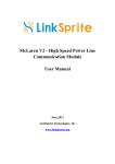
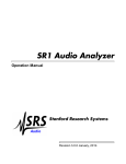
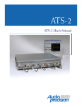
Testing for Optimal Results
ATS-1
Audio Precision Quality in a
Low-Cost, Stand-Alone Test Set
Unmatched Value
ATS-1: Audio Precision Quality in a Stand-Alone Package
The ATS-1 family of audio test instruments—at home on the
bench, or in a test rack under GPIB control.
With thousands of units sold, you’ll find the ATS-1 family of audio analyzers in operation
around the world in maintenance, engineering and production facilities. Whether in broadcast, communications, bench or production use, ATS-1 offers a complete easy-to-use audio
test set ready for almost any environment. With twelve different measurement functions
selectable at the push of a button, ATS-1 is comprehensive while remaining user-friendly. Its
popularity is no less due to its outstanding performance specifications; yet ATS-1 is as affordable as lower-performing test sets.
Analog Only or full Dual Domain—Analog and Digital
The ATS-1
System replacement for
obsolete equipment:
HP8903B emulation mode
over HPIB (GPIB)
ATS-1 Access includes comprehensive analog generation and measurement, with two outputs
and two inputs. Easy-to-set-up sweep capability produces graphs of frequency response, distortion vs. frequency and even amplitude sweeps. Non-volatile storage of up to 30 tests
allows easy one-button recall of your favorite test setup. Connect ATS-1 to a compatible
printer and produce reports incorporating high-resolution graphs. If you work with digital
audio, the ATS-1 Dual Domain® model adds AES3/SPDIF audio and interface measurement ca-
Unparalleled Precision
pabilities to the comprehensive analog capabilities of the ATS-1 family.
Low Distortion
Analog+Digital+AES3/SPDIF: the ATS-1 Dual Domain
Analog System THD+N 80 kHz BW –92 dB
ATS-1 Dual Domain® is a comprehensive audio test set for both analog and digital audio, as
Digital Distortion THD+N £–140 dB
well as for generation and measurement of AES3/SPDIF digital interface characteristics such
High Analog Bandwidth
as jitter. Like our 2700 Series family of instruments, ATS-1 Dual Domain features true dual
Signal Generation to 120 kHz
domain architecture. Digital signals are generated and measured purely in the digital do-
Low Noise
main, resulting in the extremely low distortion and noise residuals necessary for making
22 Hz–22 kHz < –114 dBu
useful digital audio measurements.
A-weighted < –118 dBu
Wide Input Voltage Range
Input Range 80 mV–250 V in 10 dB steps
Flat Response
20 Hz–20 kHz ±0.05 dB
Low Crosstalk
Input < –120 dB
Output < –110 dB
Low Jitter
Generator < 0.8 ns
Analyzer < 1.6 ns
Performance, Measurement Power, and Ease-of-Use
Easy to Use
Analog Performance:
Measurement functions are simply selected
The low distortion transformer-coupled ana-
from the front panel. Just press a button
log generator supplies a full +30.17 dBu
and make the
used, the setting knobs and
measurement. Se-
buttons also provide a con-
lection of analog
venient human interface for
and digital inputs
scrolling display cursors
is clearly indi-
and for entry of other set-
cated on the front
tings and data.
panel with LED
legends. ATS-1
makes graphs of
swept measurements in real time
on the high contrast back-lit LCD display,
including both frequency and amplitude
sweeps. Hard copy high-resolution graphs,
(+29.5 dBm into 600 W) at selectable
(50 W, 150 W or 600 W) source impedances. Extremely low analyzer noise and
residual distortion support measurement of
high performance digital devices.
Analog Convenience Functions:
In addition to the above measurements, the
Stereo:
ATS-1 Dual Domain is a true two channel instrument. Both analog and digital level
functions measure both inputs simultaneously. Phase and level ratio
measurements are also available.
Full Range of Analog & Digital Testing
Facilities:
ATS-1 Dual Domain provides complete and
analog GEN LOAD function measures the input resistance of your device at any
frequency you choose and makes swept impedance measurements (including
loudspeakers).
AC MAINS CHECK measures the voltage, frequency and distortion of the power line
without hazardous direct connections.
BARGRAPH display in AC MAINS CHECK function provides a visible history of maximum
and minimum mains voltage excursions.
compact screen-sized graphs or tabular data
parallel measurement capabilities for both
listings can be made from your ATS-1 to la-
analog and digital audio signals. Measure-
ser or ink jet printers at the touch of a
ments common to both domains include:
button. Bargraphs can display measure-
Amplitude, Noise, Level (2 channels simul-
ments ranging from AC mains power line
taneously), Frequency, Phase, THD+N,
distortion to digital interface error rate
SMPTE/DIN, IMD, Crosstalk and Level Ratio.
The dBg unit (dB referred to the present an-
…and nearly everything in between. Sepa-
Standard A-weighting, CCIR 468, and LP/HP
alog generator amplitude) is useful for
filters are included in both domains. RMS
compression threshold measurements or
and quasi-peak (CCIR 468) detectors are
rapid response sweeps at several different
available in both domains.
absolute levels, as well as for input to output gain/loss measurements.
600 W Analog Input Terminations are indi-
rate buttons and knobs provide independent
vidually switchable for each channel of the
control of frequency and amplitude. The
analog analyzer.
buttons provide large and medium steps
(decade and 1/3 octave steps for frequency,
10 dB and 1 dB for amplitude), with knobs
for finer resolution. When not otherwise
Turn on ATS-1: Audio Testing to Meet Your Challenges
Comprehensive Analog and
Digital Functions
Digital Performance:
fect on THD+N, IMD, or noise. Competitive
ATS-1 Dual Domain uses a true DSP-imple-
units can drive only one domain at a time
mented analyzer for digital measurements,
or use their analog generator to create the
which results in –130 dB residual THD+N,
digital jitter, and thus can’t make this mea-
0.01 dB flatness, and –140 dBFS residual
surement at all.
noise. Other mixed-signal test sets in the
Separate Digital Inputs & Outputs:
jitter meter: a 700 Hz high-pass filter used
for residual jitter measurements according
to AES standards, and a 50 Hz high-pass filter for jitter response measurements.
Other Interface Signal Measurements:
ATS-1 Dual Domain measures key digital I/O
interface parameters in addition to jitter,
including sample rate, AES signal voltage,
frame delay through the device under test,
and delay of the input signal relative to a
same price range have no digital analyzer,
house sync reference (frame or block).
but use a D/A converter and an analog analyzer. These architectures “bottom out” at
–70 dB to –84 dB residual THD+N (12–14
bit effective performance), and 0.1 dB flatness. With today’s best A/D converters
measuring –108 to
–112 dB THD+N,
their real performance is invisible
to these mixed signal analyzers
…buried under the
analyzer’s noise and
distortion floor.
A competitive instrument lacking a
DSP analyzer produces false THD+N
readings (red trace) from a popular A/D converter; but both the
ATS-1 Dual Domain and the Audio
Precision 2700 Series graph the
true performance of the converter
(from 5 dB to 28 dB lower), as
shown by the blue trace.
Separate & Independent Analog & Digital
Generators:
Often necessary for dual domain testing.
You may, for example, drive the inputs of an
A/D converter with the low-distortion analog sine while simultaneously driving the
converter’s digital reference (house sync)
input with the digital generator. Then, add
jitter or vary the sample rate to see the ef-
Three I/O formats: XLR, BNC, and optical
(Toslink®). All are completely separate from
the analog audio XLR connectors, permitting both digital and analog generators to
operate simultaneously. No cable changes
Flexible Interface Impairment Simulation:
required to go from A/D to D/A to D/D to
Flexible digital interface testing is vital for
A/A testing of a digital tape machine, for
troubleshooting and verifying performance
example.
of digital audio at the systems level. ATS-1
Dual Domain allows simulation of real world
Digital & Analog Monitors:
transmission and interface problems.
Listen to all measurements in the digital
and analog domains over the
internal loudspeaker or a
pair of headphones. In the analog domain, monitor
signals or distortion. In the digital domain,
the incoming signal, distortion, or jitter
can all be monitored.
Jitter Meter:
ATS-1 Dual Domain includes jitter measurement in nanoseconds or in Unit Intervals.
Two filter selections are provided for the
Vary the digital output signal to test the acceptance range of your digital devices. Set
sample rate anywhere from 28.8 kHz to
52.8 kHz, not just at the three standard
frequencies. Inject jitter amplitude from
0 UI to 2.5 UI (415 ns at 48 kHz) in
0.01 UI (1.6 ns) steps, or 0 UI to 25.5 UI
(4150 ns) in 0.1 UI (16 ns) steps.
Injected jitter frequency can be set from
10 Hz to 38.8 kHz, not just to a fixed frequency. Adjust output signal amplitude
Dither amplitude is automatically set to the
continuously from zero to 5.12 Volts in
proper value for the output word length
5 mV increments, not just at a few steps.
and the selected probability function.
Independent Interface I/O Word Lengths:
Sample & Frame Sync:
Word length (resolution) of digital input
Synchronize ATS-1 Dual Domain sample and
and output are independently set from 16
frame sync to the digital reference (house
to 24 bits. Output resolution is set to match
sync) input.
the device under test to assure proper
analysis techniques are compatible with the
dither. Input resolution must be set to ex-
BITTEST feature of our System products, so
clude signal in the AUX bits or other low-
you can test a transmission link end-to-end
Digital Pass Mode:
level bit activity meaningless to the desired
with an ATS-1 Dual Domain at one end and a
Sends the input digital audio content to
measurement.
System Two, Cascade or 2700 Series dual
the output while modifying status bytes,
domain instrument at the other.
validity bit, etc. ATS-1 Dual Domain can
thus be used as a problem-solver between
Other Digital Convenience Functions:
incompatible equipment.
Digital Status bytes are displayed and set in
Independent Input & Output Sample Rates:
high-level English.
Signal Monitoring Outputs:
A digital signal appropriate for syncing an
Lets you test sample rate converters. Mea-
external oscilloscope may be derived from
surement of the incoming embedded audio
the input sample rate, output sample rate,
signal can be referred to the incoming sam-
input block rate, output block rate, digital
ple rate, status byte indication of rate, or
audio waveform, jitter signal, or the de-
the outgoing generator rate.
tected interface errors. A buffered version
of the balanced AES3 signal from the XLR
input is also available, which coupled with
Error flag displays for confidence, lock, cod-
Dataü Error Testing Capability
for Digital Audio Signals:
Stimulate the test device with random data
and display current or totaled error measurements on both channels. The signal and
ing, parity errors and the validity bit are
included.
Additional active bit and actual bit displays
on the panel help determine the word
length of the incoming signal and detect
stuck bits.
Digital Dither:
ATS-1 Dual Domain includes a full complement of dither selections—triangular and
rectangular probability distribution functions; white or shaped spectrum.
the high input impedance of the XLR in
bridging mode allows non-intrusive digital
line measurements with conventional
ground-referenced oscilloscopes.
Connectivity, Test Results and GPIB or HPIB Automation
tings and on-line help to speed up code
development. Measurement sweep data is
Versatile Connectivity
stored in the instrument for quick batch
Choose among three different analog con-
transfers without holding up GPIB bus
nector panels for your ATS-1. The connector
traffic.
panel can be mounted on the front of your
instrument for convenience, or on the rear
Settled GPIB Readings:
of the instrument if you’d prefer your ATS-1
Reliable measurements are assured by algorithms inside the instrument which
automatically compensate for varying device settling speeds. Settling can be
disabled for measurements of jitter or other
ATS-1 prints graphs, panel setups and mea-
hard-wired in a rack. All the panels come
with extra dual banana and ground lugs. The
XLR panel allows for either balanced or unbalanced measurements by using a simple
dual banana-to-BNC (or to RCA phono)
instantaneous values.
sured data either to laser (PCL compatible)
or inkjet printers. Front panel keys select
GPIB Software Drivers
two sizes of graph output (including cursor
Audio Precision supports the ATS-1 with a
data), tabular sweep data, bargraphs and
National Instruments LabView and
front panels for printing.
LabWindows CVI driver for C and Basic pro-
adapter.
grammers. The LabWindows driver runs with
Save & Recall Tests:
for personal computers. The driver speeds
National Instruments GPIB interface cards
development of test routines by eliminating
Save 30 instrument set-
the need to learn the ATS-1 programming
ups, including sweep re-
mnemonics.
sults data, time-stamped
from the internal clock
HP8903B GPIB Emulation Mode
calendar. Use for
repeatable, easy bench and production testing or when in the field, for storing test
ATS-1 also emulates the HP8903B audio analyzer HP command set for a simple
data to be printed or analyzed later. Each
saved test includes all settings for the entire instrument, a default description or
your own title for the test, the date and
time, and the last test sweep result data.
IEEE-488.2 GPIB Port:
An IEEE-488.2 GPIB interface port is included on the ATS-1. The commands closely
model the front panel interface to make
software development more productive. ATS1 provides full query back of all manual set-
replacement of slow and outdated equipment in existing systems. A front panel
button selects between the Audio Precision
488.2 (GPIB) command mode and the HPIB
command mode.
ANALOG SIGNAL OUTPUTS
Low Distortion Sine Wave
Frequency Range
Frequency Accuracy
Amplitude Range
Balanced
Unbalanced
10 Hz to 120 kHz
±0.5 %
(20 Hz to 30 kHz)
<0.25 mV to 26.25 Vrms [–70 dBu to
+30.6 dBu]
<0.25 mV to 13.12 Vrms [–70 dBu to
+24.6 dBu]
±0.2 dB [±2.3 %] at 1 kHz
0.01 dB
Amplitude Accuracy
Amplitude Resolution
Flatness (1 kHz ref)
10 Hz–20 kHz
±0.05 dB
Residual THD+N
25 Hz–20 kHz
£(0.0025% + 3 µV), 80 kHz BW [–92 dB]
Square Wave
Frequency Range
20 Hz–30 kHz
Amplitude Range
Balanced
0.71 mVpp to 34.73 Vpp
Unbalanced
0.71 mVpp to 17.36 Vpp
Amplitude Accuracy
±0.3 dB [±3.5 %] at 400 Hz
Rise/fall time
Typically 2.5–3.0 µs
SMPTE (or DIN) Test Signals with option “ATS-IMD”
LF Tone
50, 60, 70, or 250; all ±1.0 %
HF Tone Range
7 kHz or 8 kHz (±1 %)
Mix Ratio
4:1 (LF:HF)
Residual IMD
0.0015 % [–96.5 dB], 60 Hz + 7 kHz
or 250 Hz + 8 kHz
OUTPUT CHARACTERISTICS
Source Configuration
Selectable balanced or unbalanced
Source Impedances
Balanced
50 W (±2 W), 150 W (±2 W), or
600 W (±6 W)
Unbalanced
50 W (±2 W)
Output Current Limit
75 mA peak
Max Output Power
Balanced
+29.9 dBm into 600 W (Rs = 50 W)
Unbalanced
+23.8 dBm into 600 W (Rs = 50 W)
Output Related Crosstalk
£–110 dB or 10 µV, whichever is
greater
(10 Hz–20 kHz)
ANALOG ANALYZER
ANALOG INPUT CHARACTERISTICS
Input Ranges
80 mV to 250 V in 10 dB steps
Maximum Rated Input
350 Vpk, 140 Vrms (dc to 20 kHz);
overload protected
Input Impedance
Balanced (each side)
Nominally 100 kW // 150–200 pF
Unbalanced
Nominally 100 kW // 150–200 pF
Terminations
Selectable 600 W ±1 %
CMRR 80 mV–2.5 V range
³70 dB, 50 Hz–20 kHz
Input Related Crosstalk
£–120 dB or 1 µV, whichever is
greater
10 Hz–20 kHz
Wideband Amplitude/Noise Function
Measurement Range
<1 µVrms to 140 Vrms [–118 dBu to
+45 dBu]
Accuracy (1 kHz)
±0.2 dB [±2.37 %] unweighted
Flatness (1 kHz ref)
±0.05 dB (20 Hz–20 kHz)
Bandwidth Limiting Filters
LF –3 dB
<10 Hz; 400 Hz ±5 % (3-pole)
HF –3 dB
22 kHz; 30 kHz; 80 kHz (3-pole), or
300 kHz
Weighting Filters
ANSI-IEC “A”; CCIR-QPK; CCIR-ARM;
CCIR-RMS
Optional Filters
Up to 2 (Aux 1 and Aux 2)
Detection
RMS (i=60 ms); AVG; QPK (CCIR
Rec 468)
Residual Noise
22 Hz–22 kHz BW
£1.5 µV [–114 dBu]
A-weighted
£1.0 µV [–118 dBu]
CCIR-QPK
£5.0 µV [–104 dBu]
Frequency Meter Related (both channels)
Measurement Range
10 Hz–200 kHz
Accuracy
±0.01 % [±100 PPM]
Resolution
5 digits
Phase Measurement Related
Measurement Ranges
±180, +90/–270, or –90/+270 deg
Accuracy 20 Hz–20 kHz
±2.0 deg
Resolution
0.1 deg
Level Meter Related (both channels)
Measurement Range
10 mV to 140 V for specified
accuracy and flatness, useable to
<100 µV [–38 dBu to + 45 dBu]
Accuracy (1 kHz)
±0.1 dB + 100 µV
Flatness (1 kHz ref)
(Vin >10 mV) ±0.05 dB
(20 Hz–20 kHz)
Bandpass Amplitude Function
Tuning Range (fO)
20 Hz to 120 kHz
Bandpass Response
Q=5 (2-pole)
Accuracy (at fo)
±0.3 dB, 20 Hz–120 kHz
THD+N / SINAD Function
Fundamental Range
10 Hz to 100 kHz, THD+N mode
Measurement Range
.001 %–100 %
SINAD Range
400 Hz–1 kHz
Accuracy
±1 dB, 20 Hz–120 kHz harmonics
Measurement Bandwidth
LF –3 dB
<10 or 400 Hz
HF –3 dB
22k, 30k, 80k, or 300 kHz
Residual THD+N
25 Hz–20 kHz
£(0.0025% + 3.0 µV), 80 kHz BW
[–92 dB]
Crosstalk Function
Frequency Range
10 Hz to 120 kHz
Measurement Range
–140 dB to 0 dB
Accuracy
±0.5 dB
SMPTE (DIN) IMD Function with option “ATS-IMD”
Test Signal Compatibility
40–250 Hz and 3 kHz–20 kHz in
0:1 to 8:1 ratio
IMD Measured
Amplitude modulation products of
the HF tone.
Measurement Range
<0.0025 %–20 %
Accuracy
±1 dB per SMPTE RP-120-1983,
DIN 45403
Residual IMD
£0.0025% [–92 dB], 60 + 7 kHz or
250 + 8 kHz
Wow & Flutter Function
Test Signal Compatibility
2.80 kHz–3.35 kHz
Accuracy (4 Hz)
±(5 % of reading + 0.002 %)
Detection Modes
IEC/DIN; NAB; JIS
Residual W+F
£0.005% Weighted; £0.01%
Unweighted
DIGITAL SIGNAL GENERATOR
DIGITAL OUTPUT CHARACTERISTICS
Output Formats
AES/EBU (per AES3-1992); SPDIFEIAJ; Optical
Sample Rates
28.8 kHz–52.8 kHz
Sample Rate Accuracy
±0.002% [±20 PPM] lockable to
external reference
Word Length
16 to 24 bits (even values)
Sine Wave
Frequency Range
10 Hz to 47 % of sample rate
(22.56 kHz at 48 ks/s)
Frequency Resolution
Sample Rate ¸ 223
(typically 0.006 Hz at 48 ks/sec)
Flatness
±0.001 dB
Residual Distortion
±0.00001 % [–140 dB]
Square Wave
Frequency Range
10 Hz to 1/6 sample rate
Frequencies available
fs ¸ 4096 to fs ¸ 6, in even integer
divisors
SMPTE/DIN IMD Waveform with option “ATS-IMD”
Upper Tone Range
Choice of 7 kHz or 8 kHz
Lower Tone Range
Choice of 50 Hz, 60 Hz, 70 Hz, or 250 Hz
Amplitude Ratio
4:1 (LF:HF)
Residual Distortion
£0.00001 % [–140 dB] at 4:1 ratio
Random Generator Waveform
Waveform
Compatible with Audio Precision
BITTEST
Dither (all waveforms)
Probability Distribution
Triangular or rectangular;
independent for each channel
Spectral Distribution
Flat (white) or Shaped (+6 dB/oct,
triangular only)
Amplitude
Automatically tracks word length or off
AES/EBU INTERFACE GENERATION
Interface Signal
Amplitude Range
Balanced (XLR)
Unbalanced (BNC)
Channel Status Bits
Validity Flag
AES/EBU Impairments
Induced Jitter
Jitter Freq Range
Jitter Amplitude
0–5.11 Vpp, into 110 W in 5 mV steps
0–1.62 Vpp, into 75 W in 1.6 mV steps
English language decoded,
Professional/Consumer
Selectable, set or cleared
Sine wave
10 Hz to 38.8 kHz
0–1.28 UI (pk), in steps of 0.005 UI
or better
1.3–12.75 UI, in steps of 0.05 UI or
better
(total generator/analyzer) peak calibrated
£0.005 UI (700 Hz–30 kHz BW)
£0.015 UI (700 Hz–30 kHz BW)
Residual Jitter
RMS response
Peak response
Spurious Jitter Products
Jitter & Ref Delay Off
£0.0005 UI
Jitter On
£–30 dB below jitter signal
REFERENCE INPUT CHARACTERISTICS
Input Formats
AES/EBU (per AES3-1992)
Input Sample Rates
28.8 kHz–52.8 kHz
Lock Range
±0.0025% [±25 PPM]
Narrow Band Amplitude
Frequency Range
Filter Shape
THD+N Measurements
Fundamental Range
0.04% to 40% of sample rate
(10 Hz–19.2 kHz at 48.0 ks/sec)
10-pole, Q=19 (BW = 5.3% of f0)
0.02% to 45% of sample rate
(10 Hz–22.0 kHz at 48.0 ks/sec
£–138 dBFS
22 Hz, 400 Hz 2-pole Butterworth
15 kHz, 20 kHz 6-pole elliptic lowpass
Weighting Filters
ANSI-IEC “A” weighting; CCIR QPK;
CCIR RMS
SMPTE (DIN) IMD Function with option “ATS-IMD”
Test Signal Compatibility
40–250 Hz and 3 kHz–20 kHz in 1:1
to 4:1 ratio
IMD Measured
Amplitude modulation products of
the HF tone.
Measurement Range
<0.0001%–10%
Accuracy
±1 dB per SMPTE RP-120-1983,
DIN 45403
Residual IMD (0 dBFS)
£0.0001% [–120 dB], 60 + 7 kHz or
250 + 8 kHz
Frequency Measurements
Range
5 Hz to 47% of sample rate
Phase Measurement Related
Measurement Ranges
±180, +90/–270, or –90/+270 deg
Accuracy
±2.0 deg (20 Hz–20 kHz)
Resolution
0.1 deg
BITTEST Measurement
Measurement
Compatible with random mode of
Audio Precision BITTEST
Residual THD+N
High pass Filters
Low pass Filters
DIGITAL INTERFACE MEASUREMENTS
AES/EBU Impairments, Real Time Displays
Input Sample Rate
±0.002% [±20 PPM] internal ref,
±0.0001% [*1 PPM] external ref
Output to Input or Reference Measures status propagation from
the AES/EBU output to the input.
Input to Input Delay
Range is 0–192 (frames), resolution
±60 ns.
AES/EBU Input Voltage
Balanced
400 mV to 10.24 Vpp,
±(10% + 50 mV)
Unbalanced
100 mV to 2.56 Vpp,
±(10% + 30 mV)
Jitter Amplitude (500 Hz)
(peak-peak sine wave calibrated)
0–10 UI,
Jitter Flatness
±1.5 dB, 100 Hz–22 kHz (50 Hz HP
selection, RMS detection, 48 kHz
sample rate)
Residual Jitter, peak calibrated (analyzer only) (700 Hz–30 kHz
BW)£0.01 UI RMS; £0.03 UI Peak
Spurious Jitter Products
£0.002 UI (1.2 kHz) or 0 dB below
jitter signal
Channel Status Bits
English language decoded
(Professional/Consumer)
Validity Flag
Displayed for selected channel
Parity; Signal Confidence;
Displayed for total signal (both
channels combined)
Receiver Lock; Coding Error
AUXILIARY SIGNALS
Generator Analog Sync Output; Digital Sync Output; Analyzer Input
Monitor; Analyzer Reading
AUDIO MONITOR
Power Output
Typically 1 watt
GENERAL / ENVIRONMENTAL
Power Requirements
Temperature Range
DIGITAL ANALYZER
Humidity
DIGITAL INPUT CHARACTERISTICS
Input Formats
AES/EBU (per AES3-1992); SPDIFEIAJ; Optical
Sample Rates
28.8 kHz–52.8 kHz
Word Length
16 to 24 bits
EMBEDDED AUDIO MEASUREMENTS
Wideband Level/Amplitude
Range
0 dBFS to –140 dBFS
Frequency Range
<10 Hz–22.0 kHz at 48 ks/sec
Accuracy
±0.01 dB, ³–90 dBFS
Flatness
±0.01 dB, 15 Hz–22 kHz
High pass Filters
22 Hz, 400 Hz, 2-pole Butterworth
Low pass Filters
15 kHz, 20 kHz 6-pole elliptic lowpass
Weighting Filters
ANSI-IEC “A” weighting; CCIR QPK;
CCIR RMS
Residual Noise
–140 dBFS unweighted; –142 dBFS
A-weighted
EMC
Dimensions
Weight
Safety
100/120/230/240 Vac (–10%/+6%),
50–60 Hz, 50 VA max
0° C to +50° C Operating; –20° C to
+60° C Storage
90% RH to at least +40° C (noncondensing)
Complies with 89/336/EEC, CISPR 22
(class B), and FCC 15 subpart J (class B)
16.5 x 6.0 x 13.6 inches [41.9 x 15.2
x 34.5 cm]
Approximately 20 lbs [9.1 kg]
Complies with 73/23/EEC,
93/68/EEC, EN61010, and IEC 1010
(including Amendments 1 and 2)
ATS-1 Dual Domain Block Diagram
WOW &
FLUTTER
DISCRIMINATOR
CHANNEL
A
SQUARE
WAVE
GENERATOR
MEASUREMENT
AMPLIFIER
BAND PASS
BAND REJECT
FILTER
INPUT
TERMINATION
ANALOG
INPUT
INPUT
PREAMP
and
ATTENUATOR
PRIMARY
READING
DETECTOR
WEIGHTING
FILTERS
SOURCE
IMPEDANCE
OUTPUT
ATTENUATOR
MAIN
OSCILLATOR
PHASE/FREQ
COMPARATORS
CHANNEL
B
OUTPUT
AMPLIFIER
SIGNAL
SUMMATION
SECONDARY
READING
DETECTOR
CHANNEL
A
ANALOG
OUTPUT
BALANCING
TRANSFORMER
CHANNEL
B
INPUT
TERMINATION
INTERMOD
DEMODULATOR
ANALOG
TRIGGER
OUTPUT
FUNCTION
MONITOR
IMD HF TONE
GENERATOR
INTERMODULATION DISTORTION OPTION
INPUT
MONITOR
SPEAKER/
HEADPHONE
MONITOR
MICROPROCESSOR
LCD DISPLAY
IEC60958
INPUT
AC/DC
M
U
X
AES3
INPUT
OPTICAL
INPUT
AES3
RECEIVER
MONITOR
D-to-A
JITTER
DETECTOR
A-to-D
DSP
Generator Waveform Trigger
OPTICAL
RECEIVER
Jitter Signal
Output Clock
DELAY
LOGIC
AES3
REFERENCE
INPUT
M
U
X
Input Clock
CLOCK
GENERATOR
SYNC
JITTER
GENERATOR
IEC60958
OUTPUT
AES3
TRANSMITTER
JITTER
MODULATOR
AES3
OUTPUT
DRIVER
OPTICAL
DRIVER
BUYING AN ATS-1 ANALYZER FOR
ANALOG AND DIGITAL AUDIO:
Ordering Information
ATS-1A
ATS-1 Access Audio Test System with GPIB interface
ATS-1DD
ATS-1 Dual Domain (digital and analog) Audio Test System with
GPIB interface
Select panel type and front or rear connections at time of order:
ATS-BNC: BNC and banana jack connector panel
ATS-XLR: XLR and banana jack connector panel
ATS-PHJ: ¼-inch phone and banana jack connector panel
ATS-R: Rear mount (front mount connector panel is default)
Options and Accessories for ATS-1 Instruments
ATS-IMD
SMPTE/DIN intermodulation distortion measurement and generation
(analog and digital)
RAK-ATS
Rack mount shelf for ATS-1 Access or ATS-1 Dual Domain
MAN-ATSA
Additional ATS-1 Access operator’s manual (one included with
instrument)
MAN-ATSDD
Additional ATS-1 Dual Domain operator’s manual (one included with
instrument)
MAN-ATS488
Additional GPIB manual for ATS-1 Access or ATS-1 Dual Domain (one
included with instrument)
SVC-ATS
Service manual for ATS-1 Access or ATS-1 Dual Domain
CAB-XMF
Set of four XLR male to XLR female cables
CAB-XBR
Set of four XLR male/female to RCA/BNC cables
CAB-AES
Set of two AES3 digital cables, 1 meter
CAB-AES2
Set of two AES3 digital cables, 2 meters
CAB-AES4
Set of two AES3 digital cables, 4 meters
ATS-1 includes a
removable carrying handle.
Portable and self-contained, take your
ATS-1 with you on the road.
pn 0057.0002 rev 0
What to look for when evaluating competitive instruments
Digital Architecture and Features:
Not all analyzers that accept a digital
input signal are actually digital analyzers. Does the instrument have a
real (DSP-implemented) digital domain analyzer, or just a D/A converter
from the digital input connector to an
analog hardware analyzer? This latter
approach in a competitive unit yields
distortion performance in the 12–14
bit range (–70 to –85 dB THD+N, for
example). There’s just not that much
12-bit digital audio around to measure anymore. ATS-1 Dual Domain’s
digital analyzer guarantees –130 dB
residual distortion (nearly 22 bit performance), far in excess of the
–108 to –112 dB actual linearity of
today’s best A/D converters.
Analog Performance: Does the instrument have an analog hardware
generator and an analog hardware analyzer? Some competitive units (at
twice the price of ATS-1 Dual Domain)
use DSP techniques for all generation
and analysis, so analog signals pass
DIGITAL
TRIGGER
OUTPUT
OPTICAL
OUTPUT
through converters inside the instrument. The result is THD+N as high as
–79 dB, flatness as poor as –0.2 dB
—inadequate for most modern audio
devices.
Interface Testing: Does the instrument have independent analog, digital, and jitter generators? If it can
only provide analog or digital output
at any one time, you can’t test a
house-synchronized A/D converter for
jitter rejection. Without independent,
flexible digital audio and jitter generators, you can’t measure jitter sensitivity of a D/A converter at various
audio and jitter frequency combinations.
True Dual Domain: True Dual Domain
hardware by definition guarantees a
full range of analysis capabilities in
both analog and digital domains. Everyone measures level and some measure THD+N (although implemented
with extremely limited performance,
as noted above). Be sure that other
useful measurements such as IMD
(Intermodulation Distortion), Phase,
and Crosstalk are available for both
analog and digital signals, not just
analog.
Testing for Optimal Results
5750 SW Arctic Drive
Beaverton, Oregon 97005
Tel 503-627-0832 Fax 503-641-8906
US Toll Free 1-800-231-7350
email: [email protected]
web: audioprecision.com
XI0607170000