1
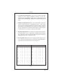
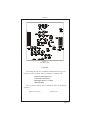
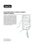
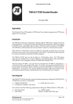
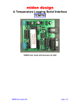
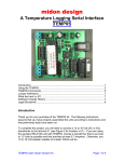
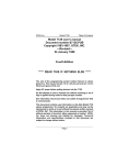
15182 Triton Lane #102 Huntington Beach CA 92649
VR-100
Vehicular
Repeater
Revision D Aug 25 1994
VR-100
Table of Contents
Specifications ..................................................................................... 1
Introduction ........................................................................................ 2
Functional Description ....................................................................... 3
Trunking Operation ........................................................................... 4
Installation .......................................................................................... 5
Jumper Selection ................................................................................ 5
Radio Connections ............................................................................. 6
Alignment ........................................................................................... 8
RF Alignment ..................................................................................... 8
Repeater Alignment ........................................................................... 9
CTCSS Table .................................................................................... 10
Figure 1 RF Test Points ................................................................... 11
Crystals ............................................................................................. 11
Figure 2 VR-100 Parts Locator ........................................................ 12
Parts List ........................................................................................... 13
Schematic ......................................................................... Fold Out
VR-100
Specifications
General:
Operation:
Modes:
Indicators:
Interface:
Adjustments:
Jumpers:
CTCSS:
Motorola PAC/RT® compatible plus trunking.
Priority, non-priority disabled, test mode.
8 high brightness LEDs, handheld queueing tones.
9 pin "D" connector with 6 ft. cable.
Receive sensitivity, transmit dev., squelch threshold,
local mic sens., lock tone decode frequency, lock
tone dev., local speaker audio.
COR polarity, on-air polarity, enable/disable polarity,
Tx audio flat/de-emph., Rx audio flat/pre-emph.
DIP switch selectable, 37 EIA tones + 69.3 & 97.4
Power Requirements:
DC supply:
Standby:
Receive:
Transmit:
13.6 VDC ±25% negative ground.
80 mA.
250 mA.
1.5 A.
Physical:
Dimensions:
Weight:
Case:
5.275"W x 6"L x 1.12"H.
18 oz.
One piece extruded aluminium.
Transmitter:
Frequency Range:
RF Power:
Tx Spurious:
Stability:
FM Noise:
Audio dist:
Tx sens:
Lock Tone:
FCC TA:
450-470 MHz
0.25-2W adjustable
-50dbc
5ppm
-55db
<5%
50mV-2.5V RMS
Jumper selectable: 832.5 or 847.5Hz
LRUVR-100U Parts 22, 90
Receiver:
Frequency Range:
Sensitivity:
Mod Acceptance:
Selectivity:
Spurious/image rej.:
IMD response:
Stability:
Lock Tone detect:
Local Rx Audio:
450-470 MHz
.4μV for 12db Sinad
±7.5kHz
70db
60db
65db
5ppm
Tunable: 820 Hz to 930 Hz, 1% bandwidth
400mW into 8 Ohms
Specifications Subject to Change without notification
Page 1
VR-100
Introduction
The Pyramid Communications model VR-100 is a microprocessor
controlled low power vehicular repeater. It is designed to interface
between a high power mobile radio and a low power UHF handheld. If
the radio operator is out of the vehicle and the mobile radio is receiving
a transmission, the VR-100 will repeat the signal to the users handheld.
The user may also transmit back to the VR-100 via the handheld, and their
transmission will be repeated back to the base by the high power mobile
radio, effectively extending the range of the low power handheld.
On-board logic control by the microprocessor ensures that only one
vehicle will become active as the repeater, should several vehicles arrive
at the same scene. The logic also handles cases where the priority vehicle
leaves the scene (or fails), or another priority vehicle arrives from a
different site.
The model VR-100 is fully compatible with Motorola PAC/RT®
systems, as well as GE Ericsson and Standard EX-10/ CTS-20 radios.
Additionally, the VR-100 supports connection to LTR® or Motorola
trunking radios, local mic audio repeat (local PTT from the mobile is
repeated to the HT's), and local speaker audio for HT-Base transmissions.
Designed to interface to a wide variety of mobile radios, the VR-100
has input and output adjustments for Rx audio sensitivity, mobile Tx
deviation, COR polarity and threshold, local mic sensitivity, local speaker
audio, on-air detect polarity, enable/disable polarity and audio response
selections for flat or 6db/octave for both Tx and Rx audio paths. There
are also jumper selections for lock tone frequency, priority sample rate,
conventional/trunking operation and a built in test mode.
The eight LED front panel status indicators confirm proper CPU
operation, priority status, and mobile/repeater COR and PTT status.
Page 2
VR-100
Functional Description
The VR-100 operates on UHF simplex frequencies; the handhelds
transmit CTCSS but are carrier squelch receive. The VR-100 has CTCSS
on receive only. The repeater should be connected to a VHF high band
or low band mobile for best operation. Connection to a UHF mobile is
possible, provided there is enough separation in the mobile transmit and
the VR-100 receive frequencies. Also, antennas for the VR-100 and the
mobile radio should be located as far apart as practical, and with vertical
separation if possible. Additionally, bandpass filters and notch cavities
may be used to reduce interference between the mobile and VR-100.
When the user leaves the vehicle, they activate the VR-100 via their
mobile radio front panel or a separate switch. When the mobile radio is
receiving carrier and proper tone, the VR-100 will begin transmitting on
the handheld's receive frequency. The user is able to hear and respond to
all radio traffic, including other handhelds at the site. The VR-100 will
cease transmission periodically to check for handheld activity. If the VR100 detects proper carrier and tone from a handheld, it will key the mobile
radio and repeat the users transmission. In this way, the handheld is given
priority and may respond during repeater hang time. The VR-100 has a
3 minute time-out timer in the base to handheld direction. If the base
transmits to the mobile for more than 3 minutes, the VR-100 will send an
error tone to the handheld, unkey the repeater and remain idle until the
base ceases transmissions.
When the VR-100 is first activated, it will transmit a short "lock tone"
that alerts the user that the system is functioning. It will then assume the
priority status and be ready to repeat any base to handheld or handheld to
base transmissions. If another unit arrives at the same site and is
activated, it too will transmit the "lock tone"; when the first VR-100
detects the lock tone from the second unit, it will increment it's priority
counter and will no longer repeat any transmissions. This process will
continue for each unit that arrives at the scene, creating a priority
hierarchy for up to 256 vehicles.
Even though the other VR-100's are not at priority status, they will
continue to monitor the channel for activity. If the priority unit were to
leave the scene or become disabled, the other units will detect the
condition to repeat and determine that there is no priority unit repeating
the transmission. They will then begin decrementing their priority
counters until one of them reaches the priority status and begins repeating
Page 3
VR-100
the transmission. Since the VR-100's are all at different priority counts,
only one will reach priority status and begin transmitting. The other units
will sense the priority repeater and cease decrementing their counters,
preserving the priority hierarchy.
If another unit were to arrive from a different scene and it is still
the active priority, there will be two active repeaters on the air when a
condition to repeat exists. When one of the VR-100's unkeys to check
for handheld activity, it will detect the presence of the other active
VR-100 and increment it's priority counter and cease transmission.
This is the self clearing mode to prevent radio "collisions".
If the user were to key the mobile radio locally and his VR-100 is
the priority, the VR-100 will detect the local mic PTT and repeat the
transmission to the other handhelds at the site so that they would not
miss half of the transmission.
If the users wish to communicate HT-HT without accessing the
mobile repeater, they may transmit on the same frequency without
CTCSS encode. The repeater will only respond to carrier and tone from
the handhelds.
Trunking Operation
When the model VR-100 is connected to a trunking radio and the
user wishes to access the system from the handheld, they key their
handheld briefly then release. The VR-100 will key the mobile radio
for 200mS, during which time it monitors the mobile's transmitter for
an on-air condition. If it does not see the radio transmit at all (system
is busy), it will retry every 5 seconds until successful or time out (30
Sec). It will also send a "busy" tone to the handheld every 5 seconds to
indicate the progress of the call attempt. If unsuccessful after 30
seconds, the VR-100 will transmit an error tone to alert the user that the
call attempt failed.
When the VR-100 detects that the mobile is transmitting, it will
continue to monitor the on-air line until the transmitter remains
keyed for at least 250 mS to ensure that the radio is not merely
handshaking or retrying. After successful acquisition of a voice
channel, it will continue to hold the mobile PTT active for 2 seconds
and transmit a go-ahead blip to the handheld user. The user then
keys their handheld to speak on the voice channel. If the user does
not key up within the 2 second period, the VR-100 will unkey the
mobile and send the error tone as before.
Page 4
VR-100
Installation
Before installing the VR-100, ensure that the RF and repeater
sections are properly aligned per the tuning procedure beginning on page
8 of this manual. Additionally, ensure that the VR-100 jumpers are
properly configured for use with the particular mobile radio that it will be
connected to:
JP1
Controls the polarity of the remote enable/disable feature of the
VR-100. If the remote enable line (pin 3 of P1) goes low to
activate the repeater, set JP1 to the (-) position. If pin 3 goes high,
set JP1 to the (+) position. If pin 3 is not used and you wish to
have the repeater active at all times set JP1 to the (-) position and
ground pin 3.
JP2
Controls the polarity of the mobile COR line. Before setting this
jumper, COR threshold adjustment (RV5) should be made as
described in the alignment section of this manual on page 9. If
the mobile COR line goes more positive in the presence of
carrier, set JP2 to the (+) position or to the (-) position if the line
goes more negative during carrier.
JP3
Controls the polarity of the on-air detect line (pin 9 of P1). This
line is only used in trunking applications. If the transmitter
sense line goes more positive during transmit, set JP3 to the (+)
position, otherwise set JP3 to the (-) position. If using a trunking
radio, ensure that JP6 is also shorted.
JP4
Controls the audio response of the mobile transmit signal. If
pin 2 of P1 is connected to the mobile transmitter audio path
before pre-emphasis, JP4 should be set to de-emph. in order to
correct for the pre-emphasized audio coming from the handheld.
If pin 2 is connected after pre-emphasis, set JP4 to flat.
JP5
Controls the VR-100 lock tone encode frequency. If JP5 is open
(default) the lock tone frequency is 832.5 Hz. If JP5 is shorted,
the lock tone frequency is 847.5.
JP6
If the VR-100 is connected to a conventional radio, leave JP6
open. If connected to a trunking radio, short JP6. If JP6 is
shorted, ensure that pin 9 of P1 is connected to a point in the radio
that indicates the radio is transmitting and ensure that JP3 is
configured properly.
Page 5
VR-100
JP7
During base to handheld transmissions, the VR-100 will
periodically unkey the repeater to check for handheld activity.
JP7 enables the priority sampling. If open, the VR-100 will not
priority sample. If JP7 is shorted, the VR-100 will sample at 1
second intervals.
JP8
Used only for testing and alignment of the VR-100. If shorted,
the VR-100 transmitter is active and the lock tone is sent
continuously. For normal operation, ensure that JP8 is open.
JP9
Controls the audio response of the repeater transmit signal. If
pin 6 of P1 is connected to the mobile's discriminator or a point
in the receiver before de-emphasis, JP9 should be set to flat. If
pin 6 is connected after de-emphasis, set JP9 to pre-emph. in
order to correct the audio for the handheld receiver.
Make the connections between the mobile radio and the VR-100
cable as follows:
Pin 1:
Ground. Connect the the radio's chassis or ground plane.
(Black/Shield)
Pin 2:
(White)
Pin 3:
(Blue)
Mobile transmit audio. Connect to the mobile transmit audio
path or tone input. If connected before pre-emphasis, ensure that
JP4 is set to de-emph. If connected after pre-emphasis, set JP4
to flat.
Remote enable/disable. Connect to the radios auxiliary output
or a separate switch to remotely enable or disable the repeater.
If this line goes high to activate the repeater, ensure that JP1 is
set to the (+) position. If this line goes to ground, set JP1 to the
(-) position. If not used ground pin 3 and set JP1 to the (-)
position; the repeater will be active any time there is 12 VDC at
pin 5.
Note: This line does not have a pull up resistor; if connected to
an open collector or dry contact output, add a 10K resistor
between pin 3 and pin 5 of P1 on the VR-100 main PCB.
Pin 4:
(Green)
Mobile PTT output. Connect to mic PTT on the mobile radio,
or a line that goes active low to transmit. This line is also used
to sense local mic PTT in order to repeat the local mic audio to
the handhelds.
Note: To disable local mic repeat, remove D4.
Pin 5:
12 VDC input. Connect to the radio's switched 12V supply.
(Red)
Page 6
VR-100
Pin 6:
(Yellow)
Pin 7:
(Violet)
Pin 8:
(Brown)
Mobile receiver audio. Connect this line to the mobile receive
audio path before the volume control. If pin 6 is connected before
de-emphasis ensure that JP9 is set to flat. If pin 6 is connected
after de-emphasis, set JP9 to pre-emph.
Mobile COR detect. This line is used to indicate when the
VR-100 should repeat the transmission to the handheld. Connect
to a logic point in the mobile that indicates proper tone and
carrier have been detected or the audio unmute line. If this line
goes more positive during an unmute condition, set JP2 to the (+)
position. If pin 7 goes more negative during unmute, set JP2 to
the (-) position. RV5 should also be set for the midway voltage
between mute and unmute. Example: If connected to a logic line
that goes between 0 and 5 VDC, set RV5 (pin 12 of U3) for 2.5
V. If pin 7 goes between 5.6 and 7.2 VDC, set RV5 for 6.4 VDC.
Local mic audio. When the user keys the mobile radio and the
VR-100 connected to it is the priority unit, the local mic audio
can be repeated to the handhelds. Connect this line to a point in
the mobile transmitter audio path after pre-emphasis but before
limiting or filtering. RV6 sets the sensitivity level.
Note: To disable local mic repeat, remove D4.
Pin 9:
(Grey)
On-air detect. Used only in trunking applications to indicate
when the mobile transmitter is actually on the air. This is not the
same as mobile PTT. Connect radio PTT on the logic board or
to switched transmitter B+. If pin 9 goes positive during
transmit, set JP3 to the (+) position. If pin 9 goes to ground
during transmit, set JP3 to the (-) position.
Install the VR-100 in the vehicle using the supplied mounting
bracket and hardware. The bracket is secured to the housing using four
8-32 x ¼" machine screws. Do not use screws longer than ¼" for
mounting the VR-100 to the bracket or circuit damage may result.
Page 7
VR-100
Alignment
In order to properly align the VR-100, you will need two service
monitors and the mobile radio that the repeater will be installed with.
Refer to figures 1 and 2 for alignment points.
Dis-assemble the repeater by removing the two allen-head screws on
the rear panel, the phillips screw on the bottom and sliding the main
circuit board out of the housing with the rear panel attached. Connect one
service monitor to the VR-100 BNC jack and the other to the mobile
antenna jack; connect the cable from the mobile radio to the VR-100.
Turn on the mobile and active the VR-100. Adjust the squelch control on
the RF board (R115) so that the repeater COR LED on the front panel is
off.
RF Alignment
Important: The case of the VR-100 is integral to the heat sink for the RF
module and voltage regulators. Do not transmit at full power for extended
periods of time with the PCB removed from the case or damage may result!
1.
Short jumper JP8 on the VR-100 main PCB. With a DC voltmeter
at TP01 on the RF board, adjust L203 and L204 for a maximum
reading.
2.
Move the voltmeter to TP02 on the RF board; adjust L203, L204,
L205 and L206 for a maximum reading.
3.
Move the voltmeter to TP03 on the RF board; adjust L205, L206,
L207 and L208 for a maximum reading.
4.
Move the voltmeter to TP04 on the RF board; adjust R232 to midway.
Adjust C244 and C247 for a minimum reading at TP04. Adjust R232
for 2 Watts. Adjust C205 for the transmit frequency ±100 Hz.
Remove the short from JP8 on the VR-100 main PCB.
5.
Set the service monitor connected to the VR-100 to generate the
repeater receive frequency with a 1kHz tone at ±3kHz deviation.
Connect a Sinadder to TP 1 on the VR-100 main PCB. Adjust the
signal generator output level for a reading of 12db Sinad.
6.
Adjust L112, L113, C147, C151, L101, C104 and L104 in that order
for a maximum Sinad reading at TP 1. Re-adjust the signal generator
output level as necessary to maintain a usable reading.
7.
Adjust C136 on the RF board for a maximum Sinad reading.
Page 8
VR-100
Repeater Alignment
1.
Set the mobile service monitor to generate mode and RF output for
1mV with a 1 kHz tone at ±3kHz deviation on the mobile receive
frequency. Set the VR-100 service monitor to the transmit monitor
mode.
2.
Mobile COR Threshold: With a positive voltmeter probe at pin
13 of U3 (VR-100), measure and record the voltage when the mobile
signal generator is both on and off. Move the voltmeter probe to pin
12 of U3 and adjust RV5 for the midway point of the 2 measurements
taken at pin 13. Set JP2 to the (+) position if the voltage at pin 13 went
more positive when the signal generator was on, otherwise, set JP2
to the (-) position.
3.
Repeater modulation limiting: Open JP7. Set RV1 on the
VR-100 main PCB fully clockwise. Turn the mobile signal generator
on and confirm that the VR-100 is keyed and the mobile COR and
Rptr PTT LEDs are on. Adjust R205 on the RF board for ±4.5kHz as
read on the service monitor connected to the VR-100. Adjust RV1
on the VR-100 main circuit board for ±3kHz deviation. Confirm that
when the mobile signal generator deviation is reduced to ±2kHz and
±1kHz, the VR-100 deviation tracks with it. Increase the mobile
signal generator deviation to ±5kHz and confirm that the VR-100
deviation does not exceed ±4.5kHz. Set JP7 per the installation
section, page 6.
4.
Lock Tone Deviation: Turn off the mobile signal generator and
short JP8 on the VR-100 main circuit board. Adjust RV3 for ±3kHz
deviation as read on the service monitor connected to the VR-100.
Remove the short from jumper JP8.
5.
Local Mic Repeat Level: Set the service monitor connected to the
mobile to the monitor mode; key the mobile radio, inject a 1kHz tone
into the mic audio circuit and adjust the audio level to produce ±3kHz
deviation. Confirm that the VR-100 is also transmitting and adjust
RV6 on the main PCB for ±3kHz deviation as read on the service
monitor connected to the VR-100. Unkey the mobile radio.
6.
Receive Audio Level: Set the service monitor connected to the
VR-100 to the generate mode and inject an RF signal at 1mV with a
1kHz tone at ±3kHz deviation. Connect a scope probe to TP1 on the
main PCB. Adjust R122 on the RF PCB for 1VPP as read at TP1.
Page 9
VR-100
7.
Lock tone decode frequency: Move the scope probe to TP2 and
change the service monitor modulation frequency to 832.5 Hz.
Adjust RV4 for a maximum reading at TP2. Confirm that the PRI
LED is off on the front panel. Return the modulation frequency to
1kHz.
8.
Mobile transmit audio level: Set the 6 position DIP switch for the
system CTCSS frequency as determined in table 1. Turn on the
service monitor CTCSS modulation at ±750 Hz deviation. Confirm
that the Rptr CTCSS and Mobile PTT LEDs are on, and the mobile
is keyed. Adjust RV2 on the VR-100 main PCB for ±3kHz deviation
as read on the service monitor connected to the mobile.
9.
Repeater Squelch level: Turn off the CTCSS deviation and reduce
the signal output to .25uV. Adjust R115 on the RF board so that the
Rptr COR LED is just off. Confirm that the LED comes on when the
signal generator level is increased to .4uV.
10. Local speaker level: Increase the signal generator output level to
1mV. Connect an 8 Ohm speaker to J1 of the VR-100 and adjust RV7
on the main PCB for the desired receive audio level.
Tone
1
2
3
4
5
6
Tone
1
2
3
4
5
6
67.0
69.3
71.9
74.4
77.0
79.7
82.5
85.4
88.5
91.5
94.8
97.4
100.0
103.5
107.2
110.9
114.8
118.8
123.0
127.3
0
0
1
0
1
0
1
0
1
0
1
0
1
1
1
1
1
1
1
1
0
0
0
0
1
0
0
0
1
0
0
0
1
0
1
0
1
0
1
0
0
0
0
0
0
0
0
0
0
0
0
0
0
0
0
0
0
0
0
0
0
1
0
0
0
0
0
0
0
1
0
1
0
0
0
1
1
1
1
1
0
1
0
0
0
1
0
1
0
0
1
0
1
1
1
0
0
0
0
1
0
0
0
1
0
0
1
1
1
0
0
1
0
1
1
0
0
1
1
0
131.8
136.5
141.3
146.2
151.4
156.7
162.2
167.9
173.8
179.9
186.2
192.8
203.5
210.7
218.1
225.7
233.6
241.8
250.3
No Tone
1
1
1
1
1
1
1
1
1
1
1
1
1
1
1
1
1
1
1
0
1
0
1
0
1
0
1
0
1
0
1
0
1
0
1
0
1
0
1
0
0
0
0
1
1
1
1
1
1
1
1
1
1
1
1
1
1
1
1
1
1
1
1
0
0
0
0
0
0
0
0
1
1
1
1
1
1
1
1
1
1
1
1
0
0
0
0
1
1
1
1
0
0
0
0
1
1
1
1
1
0
1
1
0
0
1
1
0
0
1
1
0
0
1
1
0
0
1
1
1
Note: '0' means off
Table 1
Page 10
VR-100
Figure 1
RF Test Points
Crystals
The model VR-100 uses a Standard Communications Corp. CU33
telemetry module for the RF section. Crystals are available from:
Frequency Management Co.
15302 Bolsa Chica Street
Huntington Beach CA 90649
(800) 800-9825
The crystal frequencies can be determined from the following
equations:
XtalRX=(FR-21.4)/9
XtalTX=FT/36
Page 11
Figure 2
VR-100 Main Board
Page 12
VR-100
Parts List
Reference
Description
Part #
C1,C32,C34
C2,C21
C3-C6, C33
C7
C8-C13,C22,C26-C31, C35,C37,C38
C14
C15,C16
C17,C23,C24
C18
C19,C36
C20
C25
D1,D4,D5,D6
D2,D3
F1
JP1-JP4, JP9
J1
P1
P2
Q1, Q3-Q10
Q2
RV1-RV3,RV5-RV7
RV4
R1,R4,R40
R2,R3
R10,R17,R21,R23,R24,R34,R46,R59,R60
R7,R8,R16,R18-R20,R57,R58
R36,R37,R38,R41
R6,R44
R9
R11,R12,R56
R5,R13,R28,R29,R39
R14,R15,R42,R43,R45
R22,R27,R35
R25,R26,R61
R30-R33
S1
U1,U2,U3
U4
U5
U6
U7
U8
U9
U10
VAR1
X1
.068μfd Polyester Cap
1μfd 16V Electrolytic Cap
100ufd 16V Electrolytic Cap
10μfd 16V Electrolytic Cap
.1μfd Polyester Cap
2.2μfd Tantalum Cap
33pfd Ceramic Cap
.0068μfd Polyester Cap
.001μfd Polyester Cap
.0033μfd Polyester Cap
.0022μfd Polyester Cap
4.7μfd 16V Electrolytic Cap
1N914 Pin diode
Right angle LED x4
3A Pica fuse
.100" Vertical Header
3.5mm Speaker Jack
DB-9 M Right Angle PCB
14 pin dip socket
2N4401 NPN TO92
TIP32 PNP TO220
10K Right Angle Pot
50K 10 Turn Pot
100K 1/8 Watt Carbon Film
560K 1/8 Watt Carbon Film
5.6K 1/8 Watt Carbon Film
22K 1/8 Watt Carbon Film
27K 1/8 Watt Carbon Film
33K 1/8 Watt Carbon Film
220 1/8 Watt Carbon Film
4.7K 1/8 Watt Carbon Film
2.2K 1/8 Watt Carbon Film
10K 1/8 Watt Carbon Film
1.0M 1/8 Watt Carbon Film
470K 1/8 Watt Carbon Film
18K 1/8 Watt Carbon Film
6 Position DIP Switch
MC 3403 Quad Op-Amp
8749H Microprocessor
MX-365 CTCSS Processor
4066 Quad analog switch
5V 1A Regulator
9V 2A Regulator
LM 386 400mW Audio Amp
DS 1233 Reset Controller
18V MOV
1.0 MHz xtal HC49U
Extruded Aluminium case
Aluminium Endplate
Acrylic Front panel
BNC Chassis Mt. Connector
Ribbon Cable with 14 Pin IDC Conns.
6 Ft. Radio Cable with DB-9 F Conn.
Shorting Blocks for JP1-JP4, JP9
1040-683
1032-105
1032-107
1032-106
1040-104
1031-225
1010-330
1040-682
1040-102
1040-332
1040-222
1032-475
5001-001
6001-401
7300-030
7220-103
7210-350
7400-011
7401-014
3104-401
3200-032
2101-103
2110-503
2008-104
2008-564
2008-562
2008-223
2008-273
2008-333
2008-102
2008-472
2008-222
2008-103
2008-105
2008-474
2008-183
7410-006
4003-403
4008-749
4000-365
4004-066
4007-805
4017-809
4000-386
4001-233
4900-018
8001-000
7201-001
7201-010
7201-011
7400-010
7301-002
7301-001
7400-009
Page 13
4
3
2
2N4401
12VDC
R6
33K
[-]
2
R9
[+]
820
U7
LM7805
1
1
R7
Q4
2N4401
VCC
IN
5V
3
1
C3
C4
100U
100U
R10
5k6
U2B
MC3403
U8
LM7809
IN
9VDC
9V
C6
100U
100U
4k7
7
Bias
3
C5
R56
5
6
Flat
R11
4k7
RV2
De-Emp
JP1
22K
C1
.068u
R4
100K
RV7
Local Spkr
Mob Dev
cw
cw
C31
2
7
3
.1u
C10
R13
D
C9
+
D
4
8
3
R12
U2A
MC3403
.1u
5
-
2
1
2k2
U9
LM386
12VDC
2
JP4
C8
.1u
C7
10U
3
R8
22K
3
R5
2k2
6
1
Q3
Q2
TIP117
1
18V
F1
3A
Pica
Fuse
1
VCC
VAR1
.1u
4k7
C32
Bias
C34
.068u
.068u
P1
9VDC
5
9
4
8
3
7
2
6
1
VCC
-
Q5
2N4401
D6
1N914
R20
22K
R55
CW
R19
VCC
R60
R17
5k6
R47-R54
330 Ohm
Q1
1
C16
33p
2
2
22K
Q8
2N4401
Q7
2N4401
Priority
R22
1M
C15
33p
JP3
3
R18
Power
VCC
2
I
O
1
3
U10
DS1233
Rpt Cor
C14
2U2
Rpt CTCSS
VCC
Rpt PTT
C
MCOR
MPTT
Spare
P2
X1
1.0 MHz
[-]
[+]
PROG
25
12
13
14
15
16
17
18
19
4
5
1
39
6
RESET
SS
T0
T1
INT
27
28
29
30
31
32
33
34
P1.0
P1.1
P1.2
P1.3
P1.4
P1.5
P1.6
P1.7
P2.0
P2.1
P2.2
P2.3
P2.4
P2.5
P2.6
P2.7
21
22
23
24
35
36
37
38
RD
WR
PSEN
ALE
8
10
9
11
X2
EA
U6C
4066
8
VCC
CW
C17
C19
6n8
JP5
JP6
JP7
JP8
C
Lock Tone
Trunking
Opt
Test Mode
RV1
cw
R24
C2
5k6
.1u
13
12
18K
18K
U3B
MC3403
18K
Rptr Dev
14
6
18K
9
U3C
MC3403
GND
560K
7
8
VEE
R3
5
10
R34
C13
R30
VSS
.1u
560K
R31
VDD
RV3
LTone Dev
3n3
R33
9
C11
Lock
Tone
Dev
R2
R32
Q9
2N4401
U4
8749
X1
DB.0
DB.1
DB.2
DB.3
DB.4
DB.5
DB.6
DB.7
3
7
7
6
5
4
3
2
1
J1
3mm_Jack
5k6
9VDC
8
9
10
11
12
13
14
8R_1W
D4
R59
5k6
1N914
5k6
R16
22K
2
2N4401
22K
VCC
1
Local Mic
R23
Q6
2N4401
U6A
4066
RV6
VCC
3
10K
C33
100U
JP2
[+]
2
[-]
14
11
R14
R21
5k6
6
13
9VDC
DB9_M
+
13
12
C12
.1u
U3D
MC_3403
4
10K
1
R15
RV5
COR Thresh
cw
1U
U2D
MC3403
9VDC
C18
1n
Bias
C20
2n2
R28
2k2
5k6
R1
100K
C35
C36
3n3
.1u
R57
Pre-Emp
R29
2k2
1
C21
1U
R58
TP1
JP9
2
22K
22K
2
1
B
B
3
3
Flat
U3A
MC3403
C22
.1u
C28
R27
1M
R35
50K 10Turn
27K
U1C
MC3403
Bias
3
U1A
MC3403
Bias
8
9
10
Bias
U2C
MC3403
R43
10K
R61
R44
33K
R45
10K
12
11
10
9
8
7
Q10
2N4401
5
TXI
22
4
10
C38
R25
R46
8
Bias
24
16
D0
7
5
23
17
TONE
.1u
470K
A
S1
Pyramid Communications
5k6
C25
4U7
470K
11
U6D
4066
R26
470K
D1
1N914
1
2
3
4
5
6
1N914
9
U1B
MC3403
IN
R/T
D1
D5
10K
100K
RXI
D2
10
R42
R40
6
2
18
TP2
2k2
1
PTL
MX_365
3
12
D3
R39
A
VCC
3
7
1
19
U6B
4066
C37
.1u
RX
2
10
TXO
RXO
U5
.1u
15
8
U1D
MC3403
D4
COMP
12
Bias
D5
6
R41
9
C27
21
20
DEC
14
VB
14
cw
13
LE
5
13
Rv4
LTone Dec
REF
6n8
4
27K
12
6n8
XO
C24
VSS
C23
XI
VCC
R38
27K
C30
27K
R37
11
R36
C29
.1u
VCC
1M
VR-100 Vehicular Repeater
C26
.1u
Size
CAGE Code
Rev
DWG NO
C
Monday, January 07, 2008
4
3
2
B
Scale
Sheet
1
1
of
1