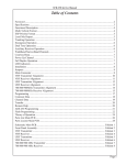
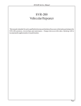
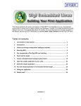
1
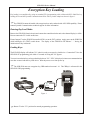
SVR-P250 Service Manual
Table of Contents
Foreword ............................................................................................................................................... 2
Specifications........................................................................................................................................ 3
Intellectual Property Rights .................................................................................................................. 3
Functional Description ......................................................................................................................... 4
Multi-Vehicle Operation ....................................................................................................................... 4
ESP Priority .......................................................................................................................................... 5
Local Mic Repeat .................................................................................................................................. 5
Trunking Operation .............................................................................................................................. 6
Emergency Operation ........................................................................................................................... 6
WideBand/NarrowBand Channels ....................................................................................................... 6
Courtesy Beep ....................................................................................................................................... 6
Power Up Channel ................................................................................................................................ 6
LED Indicators ...................................................................................................................................... 7
Installation ............................................................................................................................................ 8
Jumpers ................................................................................................................................................. 8
Main Connector .................................................................................................................................... 8
Alignment ........................................................................................................................................... 10
Programming ...................................................................................................................................... 12
Common Data ..................................................................................................................................... 13
Channel Data ...................................................................................................................................... 14
Transfer Menu .................................................................................................................................... 15
Remote Help ....................................................................................................................................... 15
Flash Programming ............................................................................................................................. 16
Encryption Key Loading ..................................................................................................................... 17
Parts List Main PCB ........................................................................................................................... 18
Parts Locator Main PCB ..................................................................................................................... 20
Schematic Main PCB.............................................................................................................. Foldout 1
Front Panel Assembly ............................................................................................................. Foldout 2
Page 1
SVR-P250 Service Manual
Foreword
Scope of this manual
This manual contains the specifications, functional description, operating instructions, schematic, parts
locator and parts list for the SVR-P250 synthesized vehicular repeater.
This manual is intended for use by qualified service technicians to aid them with installation, interfacing,
alignment and trouble shooting of the SVR-P250 when used with other land mobile radios.
Service manual revisions
Component changes, additions and deletions may occur in the circuit design to improve operation and will
be reflected in future releases of this service manual. Specifications and circuit changes are subject to change
without prior notice or obligation by Pyramid Communications.
Safety Information
The SVR-P250 is designed to operate within all applicable Federal regulations at the time of manufacture. Proper
operation and service procedures will assure continued compliance with these regulations:
•
Do not operate the SVR-P250 without an antenna or appropriate RF load connected to the antenna connector.
•
Do not operate the SVR-P250 in the presence of unshielded electrical blasting caps or explosive environmental
conditions.
•
Do not operate the SVR-P250 while refueling the vehicle or in the presence of explosive fumes.
•
Do not operate the SVR-P250 with persons standing closer than 2 feet from the mobile or repeater antenna.
FCC information
The SVR-P250 complies with the FCC rules parts 90 and 22 for radio frequency transmitters. The user must apply
for a license to operate the SVR-P250 transmitter pursuant to parts 90.243 and 90.247. Other FCC rules may apply
depending on the class of service the user qualifies for. A complete listing of FCC rules and regulations may be
ordered from:
Superintendent of Documents
Government printing office
Washington DC 20402
The following information pertaining to the SVR-P250 should be included in the FCC license application:
VHF
UHF
700/800 MHz
Type Acceptance:
LRUSVR-P250V
LRUSVR-P250U LRUSVR-P250M
Output Power:
0.25-2.0W
0.25-2.0W
0.25W-2.0W
Emission designators: 10K0F1D, 10K0F1E, 10K0F7D, 10K0F7E, 11K0F3E, 12K3F1D, 16K0F3E, 4K8F2D
7K6F1D, 8K1F1D, 8K1F1E, 8K1F7D, 8K1F7E, 8K4F2D
Frequency band:
136-174 MHz
Number of Channels: 20
Page 2
450-530MHz
20
764-870 MHz
20
SVR-P250 Service Manual
Specifications
Transmitter:
VHF
UHF
700/800 MHz
Frequency Range:
Rf power out:
Spurious emissions:
Freq stability -30°~+60°C:
Hum and Noise:
Audio response (300-3kHz):
Audio distortion:
Local mic sensitivity:
FCC Type Acceptance:
Industry Canada Approval:
136-174 MHz
500mW - 2W
-70dBc
1.5 PPM
-43/-38dB (25/12.5kHz)
Flat or +6dB/octave
<3% @ 60% deviation
300mV-5VPP
LRUSVR-P250V
2390A-SVRP250V
450-530 MHz
500mW - 2W
-70 dBc
1.5 PPM
-43/-38dB (25/12.5kHz)
Flat or +6dB/octave
<3% @ 60% deviation
300mV-5VPP
LRUSVR-P250U
2390A-SVRP250U
764-776 + 850-870 MHz
500mW - 1W
-70dBc
1.5 PPM
-40/-33dB (25/12.5kHz)
Flat or +6dB/octave
<3% @ 60% deviation
300mV-5VPP
LRUSVR-P250M
2390A-SVRP250M
136-174 MHz
.28μV
.20μV
.2μV to 2μV adjustable
75/65dB (30/15 kHz)
75db
75db
1.5 PPM
Flat or -6db/octave
0-5VPP AC coupled
400 mW 8 Ohms
450-530 MHz
.28μV
.20μV
.2μV to 2μV adjustable
75/65dB (25/12.5 kHz)
75db
75db
1.5 PPM
Flat or -6db/octave
0-5VPP AC coupled
400 mW 8 Ohms
764-776 + 850-870 MHz
.28μV
.20μV
.2μV to 2μV adjustable
75/65dB (25/12.5 kHz)
75db
75db
1.5 PPM
Flat or -6db/octave
0-5VPP AC coupled
400 mW 8 Ohms
13.6 VDC
170 mA
250 mA
1.5 A @ 2W
13.6VDC
170mA
250mA
1.75A @ 2W
13.6VDC
170mA
250mA
2A @ 1W
Receiver:
Frequency Range:
RF sensitivity Analog:
Digital (5% BER):
Squelch sensitivity:
Selectivity:
Spurious/image rejection:
IMD response:
Frequency stability:
Audio response (300-3kHz):
Audio output:
Local Rx Audio:
Power Requirements:
DC Supply
Standby
Receive
Transmit
Physical:
Dimensions:
Weight:
Case:
5.75"W x 8"L x 2.25"H
36 oz.
One piece extruded aluminium
Intellectual Property Rights
This product may be protected by one or more patents or designs of Tait Electronics Limited together with their international equivalents,
pending patents or design applications and registered Trade Marks: NZ409837, NZ409838, NZ508806, NZ508807, NZ509242,
NZ509640, NZ509959, NZ510496, NZ511155, NZ511421, NZ516280, NZ519742, NZ520650, NZ537902, NZ521450, NZ522236,
NZ524369, NZ524378, NZ524509, NZ524537, NZ524630, NZ530819, NZ534475, NZ534692, NZ535471, NZ537434, NZ546295,
NZ547713, NZ569985, AU2003281447, AU2004216984, AU2005207405, AU2005267973, AO200811677, CA2554213, CA2574670,
CN200830113833.4, EU1,532,866, EU1,599,792, EU0574655.9, EU000915475, GB23865476, GB23860110, GB2413249, GB2413445,
US11/232716, US10/597339, US10/520827, US5,745,840, US10/547653, US10/546696, US10/546697, US10/520827, US10/
547964, US10/523952, US11/572700, US29/306491.
This product may also be made under license under one or more of the following U.S. Patents: 4,590,473, 4,636,791, 4,716,407,
4,972,460, 5,146,497, 5,148,482, 5,164,986, 5,185,795, 5,185,796, 5,271,017, 5,377,229, and 5,502,767. The IMBE™ voice decoding
Technology embodied in this product is protected by Intellectual Property Rights including patent rights, copyrights, and trade secrets
of Digital Voice Systems, Inc. This voice coding Technology is licensed solely for use within this Communication Equipment. The user
of this Technology is explicitly prohibited from attempting to decompile, reverse engineer, or disassemble the Object Code, or in any
other way convert the Object Code into a human-readable form. Protected by U.S.Patents 5,870,405, 5,826,222, 5,754,974, 5,701,390,
5,715,365, 5,649,050, 5,630,011, 5,581,656, 5,517,511, 5,491,772, 5,247,579, 5,226,084, and 5,195,166.
Page 3
SVR-P250 Service Manual
Functional Description
Generally, vehicular repeaters are used as mobile extenders in cross-band operation: the link is VHF/UHF/800
MHz simplex and the mobile is Lo-band, VHF, UHF or trunking. In-band operation is possible, but care must be
taken to prevent interference between the mobile's higher power transmitter and the repeater receiver. Proper
frequency selection and antenna placement are important even in cross-band operation, but especially for inband
use. Low power pre-selector cavities may be placed in line with the repeater antenna cable since it is simplex and
low power.
) Important Note Analog Operation
The SVR-P250 is designed to operate on simplex frequencies; part of the multi-vehicle format dictates that
all of the SVR-P250s must be able to monitor all link traffic on site and be able to determine if a handheld is
transmitting, or if other repeaters are transmitting. In Analog mode, the handhelds must transmit CTCSS, but
should be carrier squelch receive. The handhelds should not use CTCSS decode if the repeater is utilizing the
multi-vehicle format, as this will interfere with the priority sampling which is essential for multi-vehicle
operation. Also, the handhelds would have to have different encode and decode tones in order for the repeater to
be able to tell the difference between handhelds and other repeaters, so the handhelds would not be able to hear
each other. The repeaters should not transmit CTCSS unless used only in a single vehicle environment.
) Important Note P25 Operation
In P25 mode, the SVR-P250 must also operate on simplex frequenices. The handhelds must transmit a
different NAC code than the SVR-P250 transmit NAC code, and the Handheld Receive NAC code must be F7Eh
(all call) in order to hear the other handhelds and the SVR-P250's which transmit different NAC codes for different
functions.
When the user leaves the vehicle, they activate the SVR-P250 via their mobile radio front panel or a separate
switch. When the mobile radio is receiving carrier and proper tone, the SVR-P250 will begin transmitting on the
handheld’s receive frequency. The user is able to hear and respond to all radio traffic, including other handhelds
at the site. In analog mode the SVR-P250 can be programmed to give the handhelds priority in a conversation by
periodically sampling for handheld activity (carrier and proper tone) during base-to-portable transmissions.
During sampling, if the SVR-P250 detects a handheld transmission, it will cease transmissions, key the mobile
radio and repeat portable-to-base. This allows the handheld to respond during repeater hang time or during full
duplex interconnect calls. Priority sampling can be enabled/disabled through PC programming and the interval
can be programmed between .25 seconds and 2.5 seconds in .25 second increments. Priority sampling is not
available in P25 mode.
The SVR-P250 has a programmable time out timer for base-to-portable transmissions. If the mobile COR is
active for more than the programmed time (and the SVR-P250 is the priority unit) it will send a double blip and
cease transmission until the mobile COR is inactive. The time-out is in affect regardless of whether the SVR-P250
is programmed for priority sampling or not.
Multi-vehicle operation
The SVR-P250 has 2 different multi-vehicle priority formats; both are compatible with the existing SVR-200
and Motorola PAC/RT formats. The new SVR-P250 with ESPTM logic has enhanced features that ensures a
priority vehicle is selected and ready to transmit during the idle time rather than during voice transmissions. The
2 formats are explained below:
SVR-200 Legacy format
When the SVR-P250 is first activated, it will transmit a short “lock tone” that alerts the user that the system
is functioning. It will then assume the priority status and be ready to repeat any base-to-portable or portable-tobase transmissions. If another unit arrives on scene and is activated, it too will transmit the “lock tone”; when
Page 4
SVR-P250 Service Manual
the first SVR-P250 detects the lock tone from the second unit, it will increment a “priority counter” and will no
longer repeat any transmissions. The recently arrived unit will be the priority repeater, and the first unit will be
1 count away from priority. This process will continue for each unit that arrives at the site, creating a priority
hierarchy for up to 256 vehicles, each with a unique count and only one unit at priority status. The SVR-P250 will
not transmit its lock tone if the radio channel is busy when first enabled. It will wait in non-priority status until
all transmissions cease, then send its lock tone and become the priority unit.
Even though the other SVR-P250s are not at priority status, they will continue to monitor the channel for
activity. If the priority unit were to leave the scene or become disabled, the other units will detect the condition
to repeat and determine that there is no priority unit repeating the transmission. They will then begin to decrement
their priority counters until one of them reaches the priority status and begins repeating the transmission. Since
the SVR-P250s are all at different counts, only one will reach priority status and begin transmitting. The other
units will sense the new priority repeater and cease counting down, preserving the priority hierarchy.
If another unit were to arrive from a different scene and it is still the active priority, there will be two active
repeaters on the air when a condition to repeat exists. When one of the SVR-P250s unkeys to check for handheld
activity (analog mode only), it will detect the presence of the other active SVR-P250 and increment its priority
counter and cease transmission. This is the self clearing mode to prevent radio collisions.
ESPTM Priority
The SVR-P250 Enhanced Sensor Priority works similar to the SVR-200 and PAC/RT formats and is
completely backward compatible with those systems. The SVR-P250 determines if there is a priority (and reestablishes the priority if missing) during idle time between conversations rather than at the critical start of a
conversation. When a condition to repeat exists, the SVR-P250 is always ready.
The priority SVR-P250 will transmit a short tone burst every 10 seconds. This serves 2 purposes: It informs
the handheld operator that they are still within range of the vehicle and it alerts the non-priority units that a priority
vehicle is still on scene. As long as the non-priority units hear this "beacon" every 10 seconds, they preserve their
counts and maintain the priority hierarchy. If the priority vehicle leaves the scene, after 10 seconds, the nonpriority vehicles will not hear the "beacon" and begin counting down. When one of the counts=0, that SVR-P250
will send lock tone for 800 mS, assume priority and begin sending the "beacon" tone every 10 seconds as before.
Since the "beacon" tone must be heard every 10 seconds, it does not have busy carrier lock out and will send the
tone if 2 handhelds are communicating directly or in the presence of co-channel interference.
Local Mic Repeat
If the handheld operator is out of the vehicle and their partner still in the vehicle were to key the mobile radio
using the local mic, the SVR-P250 will detect the local PTT and repeat the transmission to the other handhelds
so that both sides of the conversation will be heard by everyone on the link. The local mic repeat function can
be enabled/disabled via the PC software.
The SVR-P250 also has a local receive audio speaker jack that enables the person in the vehicle to monitor
portable-to-base transmissions that are being repeated through the mobile.
If the users wish to communicate portable-to-portable without accessing the mobile repeater, they may
transmit on the same frequency without tone/code (or a different tone/code); the SVR-P250 only responds to
carrier and proper tone/code from the handhelds.
Page 5
SVR-P250 Service Manual
Trunking operation
When the SVR-P250 is connected to a trunking mobile and the handheld operator wishes to access the system,
they key their handheld briefly then release. The SVR-P250 will attempt to acquire a voice channel on the trunking
system by keying the mobile for 800mS and monitoring the on-air detect line from the mobile. If it does not see
the radio transmit at all (system is busy), it will send a low tone to the hand held operator to alert them that the
system is busy. The SVR-P250 will automatically retry every 5 seconds and send busy tone to the handheld with
each unsuccessful attempt to indicate progress of the call attempt. If unsuccessful after 30 seconds, the SVR-250
will transmit intercept tone to alert the handheld operator that the call attempt failed.
When the SVR-P250 detects that the mobile is transmitting, it will continue to monitor the on-air line until
the transmitter remains keyed for at least 250mS to ensure that the radio is not handshaking or retrying. After
successful acquisition of a voice channel, it will continue to hold the mobile PTT active for 2 seconds and transmit
a go-ahead blip to the handheld operator. The user then keys their handheld to speak on the voice channel. If the
user does not key up within the 2 second period, the SVR-P250 will unkey the mobile and send intercept tone as
before.
If the user keys their handheld only once, or they key the first time for more than 1 second, the SVR-P250 will
cancel the call attempt and send intercept tone to the handheld operator. All of the queuing and error tones will
only be sent if the handheld is not transmitting to ensure that the user hears the proper tones.
The SVR-P250 can also be programmed to work in a similar way for use with the MSV mobile satellite phones,
except the time delays are extended to work properly within the network.
Emergency Operation (P25 mode Only)
The SVR-P250 can be programmed for Emergency operation on a per channel basis. If enabled, the
SVRP250 can detect an Emergency NAC code as well as portable-to-base NAC code. The Emergency NAC code is
used to indicate an Emergency condition from the portable and will assert an output pin when decoded. There
are 2 different Emergency formats: Emg output only or Emg output with voice repeat. Emg output only will assert
pin 10 on the main cable for as long as the Emergency NAC code is being received; it is used as a momentary output
to the mobile to initiate an Emergency sequence. This is the most common configuration with Motorola or MA/
Com radios. Emg output with voice repeat will assert pin 10 as before, but will also key the mobile and repeat
portable-to-base as long as the Emergency NAC code is being received. This format is used with the Tait mobiles.
Additionally, there is a solder jumper on the main logic PCB that determines if the Emg output signal pulls to
ground (NO) or breaks ground (NC).
Wide Band / Narrow Band Channels (Analog Mode Only)
The SVR-P250 can be programmed for Wide/Narrow band operation on a per channel basis. Wide band
operation is 25kHz for UHF and 800 MHz, 30kHz for VHF. Narrow band is 12.5kHz for UHF and 800 MHz,
15kHz for VHF. In addition to changing the receiver bandwidth and transmitter modulation characteristics, the
audio levels into and out of the SVR-P250 are automatically adjusted so the levels at the mobile will be correct
with either bandwidth selected.
Courtesy Beep
If enabled, the SVR-P250 will send a short beep to the handheld user at the end of each portable-to-base
transmission to confirm that the user is still within range.
Power Up Channel
The SVR-P250 can be programmed to revert to the last channel used when powered down or a preprogrammed "Home" Channel.
Page 6
SVR-P250 Service Manual
LEDs
The SVR-P250 has a 2 digit channel display as well as eight status LEDs:
CPU:
PRI:
RCOR:
RTONE:
RTX:
MCOR:
MTX:
OPT:
Flashes at a 1 Hz rate to indicate proper operation of the microprocessor.
When on, indicates that the unit is at priority count zero and will repeat all transmissions.
Repeater Carrier detect.
Repeater sub-audible decode; when on, indicates a condition to repeat portable-to-base.
Repeater transmit indicator.
Mobile unmute detector indicating a condition to repeat base-to-portable.
Mobile transmit indicator.
Emergency Tone/Code Decode.
) If the decimal point is illuminated in the 2 digit channel display it indicates a P25 channel is selected.
Page 7
SVR-P250 Service Manual
Installation
Before installing the SVR-P250, ensure that the mobile radio is properly aligned per the manufacturer's tuning
instructions. Additionally, ensure that the SVR-P250 jumpers are properly configured for use with the particular
mobile radio that it will be connected to:
J1 Controls the maximum drive level of the transmit audio output to the mobile radio. If J1 is installed, output
amp U1A will have an adjustment range of 0-100 mVPP. If J1 is removed, U1A can be adjusted between 05VPP.
J2 Controls the output impedance of the transmit audio line to the mobile radio. If connected to a low impedance
point in the mobile, installing JP2 sets the output impedance to 600 ohms. If JP2 is open, the output impedance
is 2.2Kohms. Install the jumper for radios that require a lot of modulation drive or that have low impedance
microphone circuits. Remove the jumper if the SVR-P250 installation decreases local microphone audio at
the mobile.
J4 Used to internally tie the local mic input of the SVR-P250 to the transmit audio output line which is usually
connected to the mic hi line in the mobile.
J5 Used to internally tie the on-air detect input of the SVR-P250 to the PTT output. Do so only on conventional
radios; trunking radios must have the on-air detect line connected to a line indicating that the radio is
transmitting.
J6 Changes the maximum gain of the local mic input amp from unity (Out) to 10x (In).
J7 Changes the maximum gain of the receive audio line input from unity (Out) to 7x (In).
J8 Adds a pull up (+ position) or pull down (- position) resistor to the remote enable line (blue).
J9 Adds a pull up resistor (10K to 5VDC) to mobile COR line (violet)
J10 Connects the front panel on-off control to the remote enable line to enable the SVR-P250 from the front panel.
J11 Adds (Out) or removes (In) a 100KOhm resistor in series with the Tx audio line for applications with low level
mic audio and alternator whine problems (see Service Bulletin 113).
J13 Selects the Emergency output polarity: NO=pull to ground during Emg NC=break ground during Emg.
Make the connections between the mobile radio and the SVR-P250 cable as follows:
Pin 1:
Ground. Connect to the radio's chassis or ground plane.
Black/Shield
Pin 2:
White
Pin 3:
Blue
Page 8
Mobile transmit audio. Connect to the mobile transmit audio path or tone input. If connected to the
mobile mic input, ensure that the SVR-P250 is programmed for flat (common data). If connected
after pre-emphasis, ensure that the SVR-P250 transmit audio path is programmed for pre-emphasis.
Pin 2 is AC coupled and has an output impedance of 600 or 2.2Kohms (determined by J2). RV3 sets
the transmit audio output level and J1 sets the adjustment range between 0-5VPP (J1 open) or 0100mVPP (J1 shorted).
Remote enable/disable. Connect to the radio's auxiliary output or a separate switch to remotely
enable or disable the repeater. If this line goes high to activate the repeater, ensure that JP1 is set to
the “+” position. If this line goes to ground, set JP1 to the “-” position. J8 has two positions to add
a pull up (+) or pull down (-) resistor to this line if used with an open collector or dry contact output.
J10 connects this line to the front panel on/off control.
SVR-P250 Service Manual
Pin 4:
Green
Pin 5:
Red
Pin 6:
Yellow
Pin 7:
Violet
Pin 8:
Brown
Pin 9:
Gray
Mobile PTT output. Connect to mic PTT on the mobile radio, or a line that goes active low to transmit.
Pin 4 is an open drain output rated at 2A at 15VDC.
12 VDC input. Connect to the radios 12V switched supply or a point capable of supplying at least
2A of current.
Mobile receive audio. Connect this line to the mobile receive audio path before the volume control.
If pin 6 is connected to the mobile discrimminator, ensure that the SVR-P250 receive path is
programmed for de-emphasis (common data). If connected after de-emphasis, program the receive
path for flat. Pin 6 is AC coupled and high impedance (>15K ohm). RV5 sets the receive audio level
sensitivity; this input should be between 30mVPP and 5VPP. J7 sets the gain of the receive input
amp. If open, the input has a maximum gain of one; if installed, the input has a maximum gain of
7.
Mobile COR detect. This line is used to indicate when the SVR-P250 should repeat the transmission
to the handheld. Connect to a logic point in the radio that indicates proper tone and carrier have been
detected or the audio unmute line. If this line goes more positive during an unmute condition, program
the mobile COR line as active high (common data). If the line goes more negative during an unmute
condition, program the mobile COR line as active low. The input from pin 7 is high impedance and
does not have to go rail to rail. The SVR-P250 uses a voltage comparator as a COR threshold detector
and is factory set at 1.6VDC. The COR input must go at least 0.5VDC on either side of this threshold.
Local mic audio. If programmed for local mic repeat, the SVR-P250 will go into transmit mode and
repeat the audio from this line whenever the mobile radio is keyed by the local mic. Connect this line
to the mobile transmitter audio path before limiting or filtering. This input is AC coupled and high
impedance (>5.6Kohms). The input level at this pin should be 300mV to 5VPP. RV2 sets the local
mic sensitivity. If the mic high line has sufficient drive for this input, install J4 and leave pin 8
unconnected. J6 sets the gain of the local mic input amp. If open, the maximum gain is one; if
installed, the maximum gain is 10.
On-Air detect.
Trunking: Connect to a point in the radio that indicates the mobile transmitter is actually on the air.
This is not the same as mic PTT. If pin 9 goes positive during transmit, program the on-air detect line
for active high (common data). If pin 9 goes to ground during transmit, program the on air detect line
for active low.
Conventional: Used for local mic repeat indication from the mobile. Connect pin 9 to pin 4 of the
SVR-P250 and program the on-air detect line for active low. Solder jumper J5 will connect pin 9 to
pin 4 (PTT output) and can be used on conventional systems only. Do not install J5 for trunking
operation.
Pin 10:
Black/White
Emergency Output. Connect to the Emergency input on the mobile radio. On Motorola radios, the
Emergency input opens from ground on activation and jumper J13 should be in the "NC" position.
On all other radios, the Emergency input pulls to ground on activation and jumper J13 should be in
the "NO" position.
Install the SVR-P250 in the vehicle using the supplied mounting bracket and hardware. Install the unit where
it will be easily visible by the driver and will not interfere with the drivers vision or constitute a hazard during a
vehicle collision. The SVR-P250 mounts in the bracket using the four 8-32 x ¼" machine screws. Do not use
longer screws to mount the SVR-P250 to the bracket or circuit damage may result.
Page 9
SVR-P250 Service Manual
Alignment
Before aligning the SVR-P250, ensure that the mobile radio is aligned per the manufacturer’s service
procedure; Ensure that the SVR-P250 is properly programmed and the jumpers are set per the previous section.
In order to properly align the SVR-P250, you will need two service monitors and the mobile radio that the repeater
will be installed with.
Dis-assemble the repeater by removing the two cap screws on the front panel; disconnect the front panel from
the main chassis by removing the 2 connectors. Remove the two cap screws from the rear panel and slide the main
circuit board out of the housing with the rear panel attached. Re-connect the front panel to the main PCB. Connect
one service monitor to the SVR-P250 TNC jack and the other to the mobile antenna jack. Connect the cable from
the mobile radio to the SVR-P250 (See figure 4 on page 11). Turn on the mobile and activate the SVR-P250.
Adjust the repeater squelch control (RV9) so that the repeater COR led is off. Adjust the mobile so that the audio
is squelched.
SVR-P250 Transmitter
1. Maximum deviation/lock tone deviation: Press S3 (Test) and adjust RV7 (Lock Tone) for maximum. Adjust
RV8 (repeater deviation) until the wave form just enters clipping; adjust RV7 for total 60% deviation .
Release S3.
2. Mobile COR: Measure the voltage at TP2 (R11) on the SVR-P250 main PCB and record. Ensure the mobile
COR LED on the front panel is off. Set the mobile service monitor for the mobile receive frequency, 1mV
RF output and CTCSS modulation of 15% deviation. Measure the voltage again at TP2 and record. Ensure
the mobile COR LED on the front panel is on. The 2 voltages at TP2 must be at greater than 2.1VDC and less
than 1.1 VDC.
3. RX audio sensitivity/CTCSS deviation: Set the service monitor connected to the mobile for the mobile receive
frequency and 1mV RF output. Modulate the signal generator with a 1kHz tone at 60% deviation and CTCSS
tone at 15% deviation. Ensure that the SVR-P250 mobile COR and repeater PTT LED’s are on. Adjust RV5
on the SVR-P250 main board for 75% deviation if CTCSS/DCS transmit is programmed, adjust for 60%
deviation if carrier squelch transmit, as read on the service monitor connected to the SVR-P250. Turn the RF
output from the mobile service monitor off and ensure that the SVR-P250 mobile COR and repeater PTT LEDs
are off.
4. Local mic repeat: If the SVR-P250 is programmed for local mic repeat, key the mobile local mic and inject
an audio signal into the local mic to produce 60% deviation on the service monitor connected to the mobile.
Confirm that the SVR-P250 repeater PTT LED is on; adjust RV6 for 60% deviation as read on the service
monitor connected to the SVR-P250. Unkey the mobile radio.
Page 10
SVR-P250 Service Manual
Communications
Monitor A
Mobile Radio
Interface
Cable
SVR-P250
Communications
Monitor B
Figure 4
Page 11
SVR-P250 Service Manual
Programming
Using the Software
The SVRP250CPS personalization software is used to program the SVR-P250 for all of the operating
parameters and options. The software is compatible with Windows 2000 and later operating systems The software
is menu driven and on-line help is available at any time by clicking the left mouse button on the HELP icon on
the right side of the tool bar.
Important Note:
Before attempting to program the SVR-P250 start the software and ensure the FY-4 programming cable is
plugged into the correct serial port. The com port may be selected under the “Transfer” menu. Plug the FY-4
programming cable into P7 on the front of the SVR-P250; the channel indicator should show "PC".
Menu selections
File
Open: Allows you to load a previously saved file from disk. Enter the file name or select from the Windows Dialog
box. Only files with the .P25 extension can be loaded.
Save: Allows you to save the current configuration to disk. Enter the file name to save as or select a previous file
from the Windows Dialog box to overwrite. The .P25 extension is automatically added to the file name. The
program will prompt you before overwriting an existing file.
Print: Sends the current configuration to the selected printer. Make sure the printer is on line and paper is loaded
before executing this command.
Exit: You will be asked to confirm before exiting the program. The software will also prompt you if the
configuration has changed since program start up and data has not been saved to disk.
Page 12
SVR-P250 Service Manual
Common Data
File Name: 15 character name for this profile stored
in E²PROM.
Number of Channels: Select 1-20 channels
Radio Unit ID: Used for P25 channels only,
each SVR-P250 should have a unique Radio ID.
Range is 0000001-9999999.
Band: Select the frequency band to match your
SVR-P250. Changing bands resets all data to default
values (confirmation req.)
COR Polarity: Determines if the COR signal from
the mobile is active high or low.
On-Air Polarity: Determines if the Tx indication
from the mobile is active high or low.
Radio Type: Select either Conventional, Trunking
or MSV Satellite. If Trunking or MSV is selected,
the SVR-P250 will go through the voice channel
acquisition procedure during portable-to-base repeat
mode.
Tx Audio: If the mobile Tx audio from the SVR-P250 to the mobile is connected to the mic input, select Flat
response. If connected after pre-emphasis, select Pre-Emp.
Rx Audio: If the Rx audio from the mobile to the SVR-P250 is connected to the discriminator, select De-Emp.
If connected after de-emphasis, select Flat response.
Power Up Channel: Select either Last Channel or Home Channel.
Local Mic Repeat: Enables or disables the local mic repeat function; if enabled, ensure the on-air polarity is set
correctly and the Grey wire or J5 is configured correctly (see pages 8 & 9).
Priority Sampling: If the SVR-P250 is used in a multi-vehicle environment, priority sampling must be enabled
for proper operation. Priority sampling is in effect for Analog Channels Only.
Sampling Rate: If Priority sampling is enabled, this selects the sampling interval. Range is 0.25 seconds to 2.5
seconds in .25 sec increments. The higher this setting, the longer the handheld operator must wait before speaking
after pressing PTT during base-to-portable sampling.
Time Out Timer: This is the maximum duration of a single base to portable transmission that will be allowed.
Emergency Format: Emg Out Only will assert pin 10 of the main connector for as long as secondary tone is
decoded. Emg Out with voice will assert pin 10 but also repeat portable-to-base mode.
Priority Format: The SVR-P250 has an enhanced signalling format to determine if the priority vehicle has left
the scene during idle time. Select SVR-200 legacy to turn off this feature. Both formats are fully SVR-200
compatible.
Page 13
SVR-P250 Service Manual
Channel Data
) Note: The number of channels available is determined by the setting in Common Data.
Tx and Rx Frequency: Enter the Transmit and Receive frequencies for each channel. The frequency must be
in the range for the band selected under Common Data and will be rounded to the nearest channel step.
Squelch Type: Select either CTCSS or DCS (NAC for P25). These can be selected on a per channel basis, but
cannot be mixed within a channel.
Rx Code: The primary tone/code, when received will put the SVR-P250 into portable-to-base repeat mode.
Emg Code: The secondary tone/code, when received will initiate an Emergency sequence.
Tx Code: In Analog mode, the SVR-P250 does not normally transmit sub-audible signalling. In P25 mode, the
SVR-P250 must transmit a NAC code. If enabled, the Tx code should not be the same as the Rx or Emg Code.
Lock Tone: This is the tone burst (Analog Mode) or NAC code (P25 mode) first transmitted when the SVR-P250
is enabled and sent every 10 seconds if ESPTM priority mode is selected. The tone must be the same in all vehicular
repeaters in the system.
Encrypt Key: In P25 mode this specifies which stored Encryption key is used. Range 1-16.
P25: If selected the channel will be P25 phase 1 CAI compliant. If not selected, the channel is analog.
Encrypton: If selected the channel will be encrypted (P25 mode Only).
PL Encode: If selected, sub-audible transmit is enabled for that channel (Analog Mode Only).
EMG: If selected, the Emergency function is enabled for that channel (P25 Mode Only).
NB: If selected, the channel BW is 12.5/15 kHz. If not selected the channel BW is 25/30kHz (Analog Mode Only).
Courtesy Beep: If selected, a short beep will be sent to the handheld user at the end of each portable-to-base
transmission to confirm they are still within range.
Tx Pwr: The transmitter power can be set on a per channel basis. Select 0.5W, 1W or 2W.
Page 14
SVR-P250 Service Manual
Transfer
Send: Downloads the current configuration to the SVR-P250. The program will prompt you to make the FY-4
connection before downloading. Download takes approx 2 seconds.
Receive: Uploads the current configuration from the SVR-P250. The program will prompt you to make the
FY-4 connection before uploading. Download takes approx 1 second.
Com Port: Selects the serial port to use for uploading and downloading between the PC and the SVR-P250. Comm
ports 1-8 are supported.
Help
On-line context sensitive help is available for all entry fields by selecting the field on a form and clicking on the
Help Icon on the tool bar.
Additional help menu items:
About: Gives you version information about the software and contact information for Pyramid Communications.
Remote Tech Support: Remote Tech Support is a utility that allows the Customer Service Technicians at Pyramid
Communications to remotely access your computer via the internet in order to troubleshoot any problems you
might be having with the software or to assist you in operation of the program. Please call Pyramid
Communications during normal business hours prior to selecting remote support. The Technician will give you
a password to enter and the remote connection screen will appear:
Once the internet connection is made, the Technician will be able to see your computer screen at their location
and assist you with the program. The remote connection is only active when this item is selected and can only
be enabled by the local PC user.
Page 15
SVR-P250 Service Manual
Flash Programming
The SVR-P250 uses an Atmel 89C51RB2 microprocessor which contains the operating system. The chip can be
reprogrammed in-circuit using Atmel's FLIP software and a PC running Windows 2000 or XP. The FLIP software
can be downloaded from Pyramid's web site:
www.pyramidcomm.com/support
,
Warning- Do not attempt to re-flash the SVR-P250 μP unless you are familiar with operation
of the SVR-P250 and reasonably competent using Windows software. If the μP is not programmed
correctly, it can render the SVR-P250 inoperable.
Install the software onto your PC; the download will include several config (.cfg) and hex data (.hex) files.
Ensure these are copied into the \Program Files\Atmel directory on your computer. Perform the flash
programming in the EXACT steps as outlined below:
Prior to starting the FLIP software, disassemble the SVR-P250 by removing the 2 cap screws on the front
panel. Disconnect the front panel from the main PCB by unplugging the 2 cables. Remove the 2 cap screws from
the rear panel and carefully slide the entire assembly out of the extrusion. Reconnect the front panel to the main
PCB.
Connect the radio cable to the SVR-P250 and apply power. Connect the FY-4 DB9 connector to your computer
and the modular connector to P7 at the front of the SVR-P250 main PCB; the channel indicator should show "PC".
Start the FLIP software. Install a shorting jumper onto J12.
Flash Program U3:
1. Press the Reset switch S2. In the FLIP software, press F4 (load config) and locate the Atmel directory on your
computer; select and load the SVRP250.cfg file. The FLIP software will automatically establish communications
with the IC in the SVR-P250. If it does not, wait until it times out, click OK to close the error message, check
the com port, cable etc., and start at the beginning of step 1. When FLIP is successful, it will populate the device
data fields on the right side of the PC screen. Do not change any of these settings!
2. On the left side of the screen, confirm the Erase, Blank Check, Program and Verify boxes are checked. In the
center of the screen, confirm the SVR-P250.HEX file is loaded. Click the Run button to flash U3 with the
hex file. Each of the checked boxes will turn green in series as things progress. If any of them fail, verify all
of the connections as above and start over at step 1.
Page 16
SVR-P250 Service Manual
Encryption Key Loading
Key loading is accomplished by using our standard FY-4 programming cable, a Motorola KVL-3000 Plus key
loading device and the Pyramid Communications KLA-250 key loader adapter as shown in figure 1.
)
The SVR-P250 cannot be loaded with encryption keys unless ordered with AES / DES capability. Please
contact Pyramid Communications technical support for more information.
Entering Key Load Mode:
Remove the SVR-P250 from its chassis and connect the control head to the unit so the channel display is visible.
Do not connect the FY-4 cable at this time.
Ensure Jumper J7 on the SVR-P250 controller PCB is set to the "RF" position. Apply power to the SVR-P250
while holding the S3 (TEST) switch down. The display of the SVR-P250 will indicate ". ." during the
initialization of key load mode.
Loading Keys:
The SVR-P250 display will indicate "LL" when it is ready to accept a key load device. Connect the FY-4 to the
SVR-P250 P7 programming jack within 15 seconds of seeing the "LL" appear.
You can view and write keys as long as the display shows "LL". If "Er" is displayed, a time out or communications
error has occurred with the key load device. Start the process over from power up.
The SVR-P250 must use encryption key CKR numbers between 1-16. The CKR(s) is referenced in the
)
SVR-P250 CPS programming.
Figure 1
) Return J7 to the "U3" position for normal programming operation.
Page 17
SVR-P250 Service Manual
Parts List
Reference
Description
Part #
C1,C2,C43 ........................................................................ 6.8μFd 16V tantalum chip capacitor .. 1610-25-6685
C3-C5,C10,C15,C16,C18,C25,C26,C28,C29, ................. .1μFd chip capacitor ........................... 1010-02-5104
C31-34,C37-C40
C6,C20-C22 ...................................................................... 100μFd elctrolytic cap ........................ 1400-08-7107
C7,C36,C42 ...................................................................... 2.2μFd tantalum chip capacitor .......... 1610-04-6225
C8,C9 ................................................................................ 5pFd chip capacitor ............................. 1010-02-5509
C11-C14,C41,C42 ............................................................ 2.2μFd tantalum chip capacitor .......... 1610-05-6474
C17 ................................................................................... 22μFd tantalum chip capacitor ........... 1610-05-6226
C24 ................................................................................... 2200pFd chip capacitor ....................... 1010-02-5222
C23,C35 ............................................................................ 1000pFd chip capacitor ....................... 1010-02-5102
C27,C44 ............................................................................ .01μFd chip capacitor ......................... 1010-02-5103
C30 ................................................................................... 100pFd chip capacitor ......................... 1010-02-5101
C41 ................................................................................... 3300pFd chip capacitor ....................... 1010-02-5332
D1-D4 ............................................................................... BAV99 dual diode SOT23 .................. 3110-01-0099
F1 ...................................................................................... 2A SMT Pica fuse ............................... 2610-04-0020
JP1,J17 .............................................................................. 0.1" 3 position vertical header ............ 7300-53-0103
JP12 .................................................................................. 0.1" 2 position vertical header ............ 7300-53-0102
P1 ...................................................................................... DB-15 M right angle PCB .................. 7400-00-0012
P2 ...................................................................................... 3.5mm RA speaker jack ...................... 7401-02-0051
P3 ...................................................................................... 5 circuit RA header ............................. 7301-04-0105
P4 ...................................................................................... 2 x 9 vertical header 0.1" .................... 7300-15-0209
P5 ...................................................................................... 6 circuit RA header ............................. 7301-04-0106
P7 ...................................................................................... RJ11 programming jack ...................... 7401-04-0011
P8 ...................................................................................... MCX RF connector ............................. 7400-00-0005
P9 ...................................................................................... TNC RA bulkhead connector ............. 7401-02-0007
Q1,Q2,Q5,Q10 .................................................................. 2N4401 NPN transistor SOT23 .......... 3010-01-4401
Q3 ..................................................................................... IRF-5305 P Ch MOSFET TO251 ....... 3300-26-5305
Q8,Q13 ............................................................................. N Ch MOSFET TSOP6 ...................... 3310-01-1902
Q4,Q12 ............................................................................. Dual NPN transistor TSOP6 ............... 3010-03-4210
Q11 ................................................................................... P Ch JFET SOT23 .............................. 3310-01-0175
RV8................................................................................... 200K 3mm SMT pot ........................... 2030-08-8204
RV3,RV5,RV6,RV7 ......................................................... 100K 3mm SMT pot ........................... 2030-08-8104
RV9................................................................................... 10K 3mm SMT pot ............................. 2030-08-8103
R1-R3,R5,R7-R9,R42-R44,R47,R56,R65,R68, ............... 22K chip resistor ................................. 2010-02-5223
R69,R71,R72,R77
R4,R15,R16,R29,R30-32,R63,R64 .................................. 2.2K chip resistor ................................ 2010-02-5222
R6,R14,R19 ...................................................................... 820 Ohm chip resistor ......................... 2010-02-5821
R10 ................................................................................... 5.6K chip resistor ................................ 2010-02-5562
R11,R13,R17,R23,R25,R26,R35,R38,R39, ..................... 100K chip resistor ............................... 2010-02-5104
R41,R45,R46,R51-R53,R55,R57,R12,R27 ...................... 56K chip resistor ................................. 2010-02-5563
R18,R22,R75,R76,R79,R80 ............................................. 10K chip resistor ................................. 2010-02-5103
R20 ................................................................................... 10 Ohm chip resistor ........................... 2010-02-5100
R21 ................................................................................... 8.2 Ohm 1W resistor ........................... 2000-10-5829
R24,R28,R40,R50,R74 ..................................................... 1.0M chip resistor ............................... 2010-02-5105
R33 ................................................................................... 470 Ohm chip resistor ......................... 2010-02-5471
R34 ................................................................................... 1K chip resistor ................................... 2010-02-5102
Page 18
SVR-P250 Service Manual
R36,R37 ............................................................................ 470K chip resistor ............................... 2010-02-5474
R48 ................................................................................... 24K chip resistor ................................. 2010-02-5243
R49 ................................................................................... 33K chip resistor ................................. 2010-02-5333
R54 ................................................................................... 4.7K chip resistor ................................ 2010-02-5472
R58,R59,R70,R73............................................................. 15K chip resistor ................................. 2010-02-5153
R60 ................................................................................... 220K chip resistor ............................... 2010-02-5224
R61,R62 ............................................................................ 47K chip resistor ................................. 2010-02-5473
R66,R67 ............................................................................ 330 Ohm chip resistor ......................... 2010-02-5331
R78 ................................................................................... 620 Ohm 1206 chip resistor ................ 2010-04-5621
S2,S3 ................................................................................. 3x6mm Tact Switch ............................ 7010-06-0101
TP1, Rx Ant, Tx Ant ........................................................ 1 pin header ......................................... 7300-13-0101
U1 ..................................................................................... TLC2272 dual op-amp ........................ 3410-01-2272
U2 ..................................................................................... LM386 audio amp ............................... 3410-01-0386
U3,U4 ............................................................................... AT89C51RB2 Microprocessor ........... 3611-02-8951
U5 ..................................................................................... 24C128 Serial E²PROM ..................... 3610-01-4128
U6 ..................................................................................... 74HC595 Shift Register ...................... 3510-01-4595
U7 ..................................................................................... LM7805CV 1.5A reg D2PAK ........... 3410-27-7805
U8 ..................................................................................... LM7809CV 1.5A reg D2PAK ............ 3410-27-7809
U9 ..................................................................................... LM7833CV 1.5A reg D2PAK ............ 3410-27-7833
U10,U15 ........................................................................... TLC2274 Quad op-amp ...................... 3410-01-2274
U14 ................................................................................... MCP101-300 reset controller.............. 3410-11-0300
U16-U18,U24 ................................................................... LM321 op-amp SOT23-5.................... 3410-12-0321
U19 ................................................................................... MAX32322 RS232 Driver .................. 3410-01-3232
U20,U21 ........................................................................... 4053 Analog Mux ............................... 3410-01-4053
U22,U23 ........................................................................... Max4583 Analog Mux ........................ 3410-01-4583
VAR1 ................................................................................ 18V MOV ........................................... 2580-02-0018
X1 ..................................................................................... 14.7456 MHz CSM7 ........................... 6010-01-1474
Extruded aluminium case .................... 8100-01-0250
Aluminium end panel .......................... 8200-04-0250
Rear panel gasket ................................ 8200-07-0252
4.5" Dual MCX cable ......................... 7504-04-0505
10ft. radio cable with DB-15F conn. .. 7500-10-1201
Shorting block for JP1 ........................ 7200-03-0102
Mounting bracket ................................ 9600-05-0250
4-40 SS jack screw .............................. 8000-42-4404
8-32 x ¼" SS philips ........................... 8000-24-8324
8-32 x 3/8" SS cap screw .................... 8000-34-8323
4-40 x ¼" SS philips ........................... 8000-24-4404
4-40 x .156" aluminium spacer .......... 8000-65-4425
4-40 x .250" aluminium spacer ........... 8000-65-4404
Aluminium heat sink (Tx module) ...... 8400-05-0010
Page 19
SVR-P250 Service Manual
Page 20
SVR-P250 Service Manual
Front Panel Assembly
Reference
Description
Part #
DS301 ............................................................................... 8 LED Multi-Color Display ................ 4001-08-0200
DS302 ............................................................................... 2 Digit 7 Segment LED Display ......... 4012-02-0704
P301 .................................................................................. 5 Conductor 4" cable 2mm ................. 7504-04-0504
P302 .................................................................................. 6 Conductor 4" cable 2mm ................. 7504-04-0604
RV304 ............................................................................... 20K Pot w/on-off Switch .................... 2021-04-5203
R301-R324........................................................................ 330 Ohm chip resistor 0603 ................ 2010-02-5331
RS301 ............................................................................... Rotary Quadrature Channel Switch .... 7001-04-0290
U301-U303 ....................................................................... 74HC595 Shift Reg ............................. 3510-01-4595
ABS Plastic front panel....................... 8200-03-2510
Front panel gasket ............................... 8200-08-0210
8-32 x 7/8" SS cap screw .................... 8000-34-8327
Volume Knob w/Line ......................... 8700-04-0210
Channel Knob w/o Line ...................... 8701-04-0210
Page 21