1
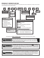
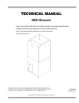
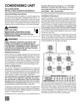
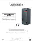
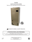
TECHNICAL INFORMATION MANUAL
ACNF, AWUF, ADPF, ARPF,
ARUF, AEPF, ASPF, ATUF
Air Handlers
Models listed
on page 3
• Refer to Service Manual RS6100004 & RS6200006
for installation, operation, and troubleshooting
information.
• All safety information must be followed as provided
in the Service Manual.
• Refer to the appropriate Parts Catalog for part
number information.
This manual is to be used by qualified, professionally trained HVAC technicians only.
Goodman does not assume any responsibility for property damage or personal injury
due to improper service procedures or services performed by an unqualified person.
Copyright © 2004-2007 Goodman Company, L.P.
RT6121000 Rev. 3
November 2007
PRODUCT IDENTIFICATION
The model number is used for positive identification of component parts used in manufacturing. Please use this number
when requesting service or parts information.
A
W
Product Type
A: Air Handler
U F
3642
1
6
A
Minor
Revision*
Electrical Supply
Cabinet
Finish
1: 208-240V/60Hz/1ph
P: Painted
U: Unpainted
N: Uncased
A
Major
Revision*
Refrigerant Charge
No Digit: R-22 Only
6:
R-410A or R-22
Application
C: Ceiling Mount PSC Motor
D: Downflow PSC Motor
E: Multi-Position
Variable-Speed Motor
S: Energy-Efficient Motor
R: Multi-Position PSC Motor
T: Coated Coils
W :Wall Mount PSC Motor
Nominal Capacity Range
@13 SEER
Dedicated Application
3636: 3 Tons
Multi-Position & Downflow Applications
3642: 3 - 3 1/2 Tons
1830: 1 1/2 - 3 1/2 Tons
@10 SEER
1729: 1 1/2 - 2 1/2 Tons (for export systems)
Expansion Device
F: Flowrator
T: TXV (Expansion Valve)
Ceiling Mount & Wall Mount Applications
(Nominal Cooling Capacity/Electric Heat kW)
1805: 1 1/2 Tons Cooling / 5 kW Electric Heat
2405: 2 Tons Cooling / 5 kW Electric Heat
3608: 3 Tons Cooling / 8 kW Electric Heat
All Airhandlers use DIRECT DRIVE MOTORS. Power supply is AC 208-230v, 60 hz, 1 phase.
WARNING
WARNING
WARNING
2
HIGH VOLTAGE!
Disconnect ALL power before servicing or installing this unit. Multiple
power sources may be present. Failure to do so may cause property
damage, personal injury or death.
Installation and repair of this unit should be performed ONLY by individuals meeting the requirements of an "entry level technician" as specified by
the Air Conditioning and Refrigeration Institute (ARI). Attempting to install
or repair this unit without such background may result in product damage,
personal injury or death.
Goodman will not be responsibile for any injury or property damage arising
from improper service or service procedures. If you install or perform
service on this unit, you assume responsibility for any personal injury or
property damage which may result. Many jurisdictions require a license to
install or service heating and air conditioning equipment.
PRODUCT IDENTIFICATION
The model number is used for positive identification of component parts used in manufacturing. Please use this number
when requesting service or parts information.
ACNF18001**
ACNF18051**
ACNF18061**
ACNF18081**
ACNF24001**
ACNF24051**
ACNF24061**
ACNF24081**
ACNF24101**
ACNF30001**
ACNF30051**
ACNF30061**
ACNF30081**
ACNF30101**
AWUF18051**
AWUF18081**
AWUF24051**
AWUF24081**
AWUF24101**
AWUF30051**
AWUF30081**
AWUF30101**
AWUF36051**
AWUF36081**
AWUF36101**
WARNING
ADPF18241**
ADPF30421**
ADPF48601**
ADPF182416**
ADPF304216**
ADPF486016**
ARPF18241**
ARPF30301**
ARPF37431**
ARPF48601**
ARPF182416**
ARPF193116**
ARPF303016**
ARPF363616**
ARPF364216**
ARPF374316**
ARPF486016**
ARUF18241**
ARUF30301**
ARUF36421**
ARUF37431**
ARUF48601**
ARUF172916**
ARUF182416**
ARUF193116**
ARUF303016**
ARUF363616**
ARUF364216**
ARUF374316**
ARUF486016**
AEPF18301**
AEPF30361**
AEPF42601**
ASPF183016*
ASPF303616*
ASPF426016*
ATUF182416**
ATUF193116**
ATUF303016**
ATUF363616**
ATUF364216**
ATUF374316**
ATUF486016**
The United States Environmental Protection Agency (“EPA”) has issued various regulations regarding the introduction and disposal of refrigerants introduced into this unit. Failure to follow these regulations may harm the
environment and can lead to the imposition of substantial fines. These
regulations may vary by jurisdiction. Should questions arise, contact your
local EPA office.
WARNING
To prevent the risk of property damage, personal injury, or death, do not
store combustible materials or use gasoline or other flammable liquids or
vapors in the vicinity of this appliance.
WARNING
Do not connect or use any device that is not design certified by Goodman
for use with this unit. Serious property damage, personal injury, reduced
unit performance and/or hazardous conditions may result from the use of
such non-approved devices.
3
PRODUCT DESIGN
WARNING
When installing or servicing this equipment, safety
clothing, including hand and eye protection, is
strongly advised. If installing this equipment in an
area that has special safety requirements (hard hats
etc.), observe these requirements. To protect the
unit when brazing close to the painted surfaces,
the use of a quenching cloth is strongly advised to
prevent scorching or marring of the equipment finish.
AIR HANDLERS
*See Air Handler Specification Sheet for Proper Combinations.
ALL AIR HANDLERS USE DIRECT DRIVE MOTORS. POWER SUPPLY IS 220-240 V, 60 HZ, 1
PHASE
Installation
Before installing this appliance insure that it is properly sized
and adequate power is available.
This appliance can be installed in the vertical or right horizontal position without modification. The horizontal left and
downflow positions require product modification.
This product is designed for zero inches (0 inches) clearance; however, adequate access for service or replacement
must be considered without removing permanent structure.
This unit can be installed on a platform when deemed necessary.
WARNING
The unit MUST have an uninterrupted, unbroken
electrical ground to minimize the possibility of personal injury if an electrical fault should occur. The
electrical ground circuit may consist of an appropriately sized electrical wire connecting the
ground lug in the unit control box to the building
electrical service panel. Other methods of grounding are permitted if performed in accordance with
the “National Electric Code” (NEC)/“American National Standards Institute” (ANSI)/“National Fire
Protection Association” (NFPA) 70 and local/state
codes. In Canada, electrical grounding is to be in
accordance with the Canadian Electric Code CSA
C22.1. Failure to observe this warning can result
in electrical shock that can cause personal injury
or death.
In an attic installation a secondary drain pan must be provided by the installer and placed under the entire unit with a
separate drain line properly sloped and terminated in an area
visible to the owner. This secondary drain pan is required in
the event that there is a leak or main drain blockage. Closed
cell insulation should be applied to the drain lines in unconditioned spaces where sweating may occur.
Appliances installed in garages, warehouses or other areas
where they may be subjected to mechanical damage must
be suitably guarded against such damage by installing behind protective barriers, being elevated or located out of the
normal path of vehicles. When installed on a base, the base
must also be protected by similar means.
Heating and cooling equipment located in garages, which
may generate a glow, spark or flame capable of igniting flammable vapors, must be installed with the ignition source at
least 18"[46cm] above the floor level.
When more than one appliance is installed in a building it
shall be permanently identified as to the area or space serviced by the equipment.
When this product is installed in the downflow installation in
an unconditioned space, remove the horizontal drain pan and
install the following insulation kit
WARNING
If this appliance is installed in an enclosed area
such as a garage or utility room with any carbon
monoxide (CO) producing appliance (i.e. automobile, furnace, water-heaters, etc.), ensure the area
is properly ventilated.
ARUF/ARPF
AEPF/ASPF
INSULATION KIT
018-032
N/A
DPI18-30/20
036-042
30
DPI36-42/20
048-061
036, 060
DPI48-61/20
This kit is used to prevent sweating on the vertical drain pan.
4
PRODUCT DESIGN
To prevent the horizontal drain pan from sweating in high
humidity applications, it is recommended that a DPIH
insulation accessory kit be used. NOTE: The DPIH insulation kit is not supplied with this product and must be
purchased separately.
See Chart below for the correct DPIH kit.
ARUF/ARPF
1729
1824
3030
1931
3636
3642
3743
4860
AEPF/ASPF
INSULATION KIT
N/A
DPIH18-32
1830
DPIH36-42
3036
DPIH48-61
4260
ACNF AC electric heat air handlers are designed for ceiling
mounting and have a direct drive, multi-speed motor. They
are available in 1-1/2, 2 and 2 1/2 ton sizes.
AWUF is a vertical stud or wall-mount electric heat air handler and features a direct drive, multi-speed motor. The AWUF
has a check flowrater for cooling only and heat pump operation, with sequence controlled heating elements of 5, 8, and
10 kW. The AWUF is available in 1 1/2 to 3 ton sizes.
rect drive motors. They are available in 1 1/2 to 5 ton sizes
with optional 3 kW to 21kW electric heat kits available for
field installation. (See note below.)
ARUF is a multi-position air handler and can be used with R410A or R-22 (models ending in 1/16) and features a direct
drive, multi-speed motor. The ARUF has a check flowrater for
cooling-only and heat pump operation. The ARUF is available in 1 1/2 to 5 ton sizes.
*AEPF is a multi-position, variable-speed air handler and can
be used with R-410A or R-22 (models ending in 1/16). The
unit's blower design includes a variable-speed DC motor and
is compatible with heat pumps and variable-capacity cooling
applications. (See note below.)
*ASPF is a multi-position air handler that can be used with R410A or R-22 and it features a X-13 motor. This motor is a
constant torque motor with very low power consumption and
it is energized by a 24V signal. The X-13 features an
integrated control module and is compatible with heat pumps
and cooling applications. (See note below.)
*NOTE: Factory-sealed to achieve a 2% or less leakage rate
at 1.0" water gauge external duct static pressure.
Complies with the Factory-sealed Air Handling Credit as
listed in the 2001 Florida Building Code, Chapter 13, Section
610.2.A.2.1.
ADPF is a dedicated downflow, multi-speed air handler and
is available in 1 1/2 to 5 ton sizes. Electric heat kits are
available as a field-installed option.
*ARPF air handlers are multi-position, multi-speed with di-
5
PRODUCT DIMENSIONS
DIMENSIONS
Model
ACNF18
ACNF24
ACNF30
AC18
AC30
AC36
6
A
37¼”
43¼”
49¼”
37¼”
43¼”
49¼”
B
3411/16”
4011/16”
4611/16”
3411/16”
4011/16”
4611/16”
C
30”
36”
42”
30”
36”
42”
D
6½”
6½”
6½”
6½”
6½”
6½”
ACNF
PRODUCT DIMENSIONS
AWUF
Small Chassis
AWUF 18 & 24
A
36"
Large Chassis
AWUF 30 & 36
A
36"
B
20 3/8"
B
24"
C
16 1/8"
C
21"
D
16"
D
19 7/8"
E
11"
E
15 7/8"
FILTER
14" X 18" X 1"
FILTER
16" X 20" X 1"
7
PRODUCT DIMENSIONS
ADPF
2 ȹ”
Model
8
A
B
C
D
E
F
G
ADPF18241/16
42ȶ”
22”
13½”
15½”
10”
3½”
6 1/16”
ADPF30421/16
53¼”
24”
20”
22”
12”
ADPF48601/16
53¼”
24”
20”
22”
12”
H
I
L
M
13ȶ” 17 15/16” 15½”
15 5/16”
9¼”
11 13/16” 19ȸ” 19 15/16” 217/16”
21¼”
9¼”
11 13/16” 19ȸ” 19 15/16” 217/16”
21¼”
PRODUCT DIMENSIONS
ARPF
J
2 ȹ”
[7.30 cm]
Model
A
B
C
D
E
F
G
H
I
J
ARPF18241*
42 1/8"
22"
13 1/2"
15 1/2"
10"
14 1/2"
11 15/16"
13 1/8"
17 15/16"
2"
ARPF19311*
46 3/4"
22"
17 1/2"
19 1/2"
10"
14 1/2"
11 15/16"
17 1/8"
17 15/16"
2"
ARPF30301*
46 3/4"
22"
17 1/2"
19 1/2"
10"
14 1/2"
11 15/16"
17 1/8"
17 15/16"
2"
ARPF36361*
46 3/4"
22"
17 1/2"
19 1/2"
10"
14 1/2"
11 15/16"
17 1/8"
17 15/16"
2"
ARPF36421*
53 1/4"
24"
20"
22"
12"
14 1/2"
11 15/16"
19 5/8"
19 15/16"
1 13/16"
ARPF37431*
53 1/4"
24"
20"
22"
12"
14 1/2"
11 15/16"
19 5/8"
19 15/16"
1 13/16"
ARPF48601*
53 1/4"
24"
20"
22"
12"
14 1/2"
11 15/16"
19 5/8"
19 15/16"
1 13/16"
9
ARUF
PRODUCT DIMENSIONS
J
2 ȹ”
[7.30 cm]
Model
A
B
C
D
E
F
G
H
I
J
ARUF172916
42 1/8"
22"
13 1/2"
15 1/2"
10"
14 1/2"
11 15/16"
13 1/8"
17 15/16"
2"
ARUF182416
42 1/8"
22"
13 1/2"
15 1/2"
10"
14 1/2"
11 15/16"
13 1/8"
17 15/16"
2"
ARUF193116
46 3/4"
22"
17 1/2"
19 1/2"
10"
14 1/2"
11 15/16"
17 1/8"
17 15/16"
2"
ARUF303016
46 3/4"
22"
17 1/2"
19 1/2"
10"
14 1/2"
11 15/16"
17 1/8"
17 15/16"
2"
ARUF363616
46 3/4"
22"
17 1/2"
19 1/2"
10"
14 1/2"
11 15/16"
17 1/8"
17 15/16"
2"
ARUF364216
53 1/4"
24"
20"
22"
12"
14 1/2"
11 15/16"
19 5/8"
19 15/16"
1 13/16"
ARUF374316
53 1/4"
24"
20"
22"
12"
14 1/2"
11 15/16"
19 5/8"
19 15/16"
1 13/16"
ARUF486016
53 1/4"
24"
20"
22"
12"
14 1/2"
11 15/16"
19 5/8"
19 15/16"
1 13/16"
10
AEPF
PRODUCT DIMENSIONS
J
2 ȹ”
[7.30 cm]
A
B
C
D
E
F
G
H
I
J
AEPF18301/16
46¾”
22”
17½”
19½”
10”
14½”
11 15/16”
17ȶ”
17 15/16”
2”
AEPF30361/16
53¼”
24”
20”
22”
12”
19ȸ”
11 15/16”
19ȸ”
19 15/16” 113/16”
AEPF42601/16
53¼”
24”
20”
22”
12”
19ȸ”
11 15/16”
19ȸ”
19 15/16” 113/16”
Model
11
PRODUCT DIMENSIONS
ASPF
J
2 ȹ”
[7.30 cm]
Model
A
B
C
D
E
F
G
H
I
J
ASPF183016*
46 3/4"
22"
17 1/2"
19 1/2"
10'
14 1/2"
11 15/16"
17 1/8"
17 15/16"
2"
ASPF303616*
53 1/4"
24"
20"
22"
12"
19 5/8"
11 15/16"
19 5/8"
19 15/16"
1 13/16"
ASPF426016*
53 1/4"
24"
20"
22"
12"
19 5/8"
11 15/16"
19 5/8"
19 15/16"
1 13/16"
12
ACNF18051
ACNF18061
ACNF18081
ACNF24001
ACNF24051
ACNF24061
ACNF24081
ANF24101
ACNF30001
ACNF30051
ACNF30061
ACNF30081
ACNF30101
ACNF
ACNF18001
PRODUCT SPECIFICATIONS
Diameter
5.75
5.75
5.75
5.75
6.31
6.31
6.31
6.31
6.31
6.75
6.75
6.75
6.75
6.75
Width
6.75
6.75
6.75
6.75
8.25
8.25
8.25
8.25
8.25
8.25
8.25
8.25
8.25
8.25
Coil Drain Connection FPT
3/4"
3/4"
3/4"
3/4"
3/4"
3/4"
3/4"
3/4"
3/4"
3/4"
3/4"
3/4"
3/4"
3/4"
Blower
Lineset Connection Size
Liquid
3/8"
3/8"
3/8"
3/8"
3/8"
3/8"
3/8"
3/8"
3/8"
3/8"
3/8"
3/8"
3/8"
3/8"
Suction
3/4"
3/4"
3/4"
3/4"
3/4"
3/4"
3/4"
3/4"
3/4"
3/4"
3/4"
3/4"
3/4"
3/4"
Electrical Data
Min. Circuit Ampacity @ 240V
0.9
27
33.5
40.5
1.68
27.8
34.3
41.3
54.9
1.68
27.8
34.3
41.3
54.9
Min. Circuit Ampacity @ 208V
0.9
2405
30.5
36.8
1.68
25.3
31.36
37.6
49.8
1.68
25.3
31.3
37.6
49
Max. Overcurrent Device 240V
15
30
40
50
15
30
40
50
60
15
30
40
50
8
60
Max. Overcurrent Device @ 208V
15
30
40
40
15
30
40
40
50
15
30
40
40
Minimum VAC
197
197
197
197
197
197
197
197
197
197
197
197
197
50
Maximum VAC
253
253
253
253
253
253
253
253
253
253
253
253
253
253
FLA
0.72
0.72
0.72
0.72
1.34
1.34
1.34
1.34
1.34
1.34
1.34
1.34
1.34
1.34
HP
1/8
1/8
1/8
1/8
1/4
1/4
1/4
1/4
1/4
1/4
1/4
1/4
1/4
1/4
Ship Weight (lbs)
59
59
59
59
69
69
69
69
69
79
79
79
79
79
Blower Motor
AC18-05D
AC18-06D
AC18-08D
AC30-05D
AC20-08D
AC30-10D
AC36-05D
AC36-08D
AC36-10D
AC
Diameter
5.75
5.75
5.75
5.75
6.31
6.31
6.31
6.31
6.31
Width
6.75
6.75
6.75
6.75
8.25
8.25
8.25
8.25
8.25
Coil Drain Connection FPT
3/4"
3/4"
3/4"
3/4"
3/4"
3/4"
3/4"
3/4"
3/4"
Blower
Lineset Connection Size
Liquid
3/8"
3/8"
3/8"
3/8"
3/8"
3/8"
3/8"
3/8"
3/8"
Suction
3/4"
3/4"
3/4"
3/4"
3/4"
3/4"
3/4"
3/4"
3/4"
Min. Circuit Ampacity @ 240V
29
36
43
29
43
58
29
44
59
Min. Circuit Ampacity @ 208V
27
33
39
27
39
53
27
39
54
Electrical Data
Max. Overcurrent Device 240V
30
40
45
30
45
60
30
45
60
Max. Overcurrent Device @ 208V
30
40
40
30
40
60
30
40
60
Minimum VAC
197
197
197
197
197
197
197
197
197
Maximum VAC
253
253
253
253
253
253
253
253
253
FLA
0.72
0.72
0.72
0.72
1.34
1.34
1.34
1.34
1.34
HP
1/8
1/8
1/8
1/4
1/4
1/4
1/4
1/4
1/4
Ship Weight (lbs)
59
59
59
59
69
69
69
69
69
Blower Motor
13
AWUF
AWUF18081
AWUF24051
AWUF24081
AWUF24101
AWUF30051
AWUF30081
AWUF30101
AWUF36051
AWUF36081
AWUF36101
Heating Capacity
Actual kW @ 240 volts
BTU/h @ 240 volts
Blower
Diameter
AWUF18051
PRODUCT SPECIFICATIONS
4.8
16,390
7.3
24,925
4.8
16,390
7.3
24,925
9.8
33,460
4.8
16,390
7.3
24,925
9.8
33,460
4.8
16,390
7.3
24,925
9.8
33,460
9"
9"
10"
10"
10"
9"
9"
9"
9"
9"
9"
Width
Coil Drain Connection FPT
Lineset Connection Size
6"
3/4"
6"
3/4"
6"
3/4"
6"
3/4"
6"
3/4"
8"
3/4"
8"
3/4"
8"
3/4"
8"
3/4"
8"
3/4"
8"
3/4"
Liquid
Suction
Electrical Data
3/8"
5/8"
3/8"
5/8"
3/8"
5/8"
3/8"
5/8"
3/8"
5/8"
3/8"
3/4"
3/8"
3/4"
3/8"
3/4"
3/8"
3/4"
3/8"
3/4"
3/8"
3/4"
Min. Circuit Ampacity*
Max. Overcurrent Device (amps)*
Minimum VAC
Maximum VAC
Blower Motor
FLA
HP
Ship Weight (lbs)
26.7/23.3 39.7/34.2 26.7/23.3 39.7/34.2 52.7/45.6 27.0/23.6 40.0/34.5 53.0/45.9 27.0/23.6 40.0/34.5 53.0/45.9
30/30
40/40
30/30
40/40
60/50
30/30
40/40
60/50
30/30
40/40
60/50
197
197
197
197
197
197
197
197
197
197
197
253
253
253
253
253
253
253
253
253
253
253
1.35
1/5
84
1.35
1/5
84
1.35
1/5
84
1.35
1/5
84
1.35
1/5
84
1.61
1/3
93
1.61
1/3
93
1.61
1/3
93
1.61
1/3
96
1.61
1/3
96
1.61
1/3
96
* @ 208V/240V
ADPF
Blower
Diameter
Width
Coil Drain Connection FPT
Lineset Connection Size
Liquid
Suction
Electrical Data
Voltage
Min. Circuit Ampacity*
Max. Overcurrent Device (amps)*
Minimum VAC
Maximum VAC
Blower Motor
FLA
HP
Ship Weight (lbs)
* @ 208V/240V
14
ADPF1824
1/16
ADPF3042
1/16
ADPF4860
1/16
9 1/2"
6"
3/4"
10 5/8"
8"
3/4"
10 5/8"
10 5/8"
3/4"
3/8"
3/4"
3/8"
7/8"
3/8"
7/8"
208/240
2.1/2.1
15/15
197
253
208/240
3.7/3.7
15/15
197
253
208/240
5.4/5.4
15/15
197
253
1.70
1/3
100
2.95
1/2
144
4.30
3/4
160
ARPF
PRODUCT SPECIFICATIONS
Blower
Diameter
Width
Coil Drain Connection FPT
Lineset Connection Size
Liquid
Suction
Electrical Data
Voltage
Min. Circuit Ampacity
Max. Overcurrent Device (amps)
Minimum VAC
Maximum VAC
Blower Motor
FLA
HP
Ship Weight (lbs)
Blower
Diameter
Width
Coil Drain Connection FPT
Lineset Connection Size
Liquid
Suction
Electrical Data
Voltage
Min. Circuit Ampacity
Max. Overcurrent Device (amps)
Minimum VAC
Maximum VAC
Blower Motor
FLA
HP
Ship Weight (lbs)
ARPF18241*
ARPF19311*
ARPF30301*
ARPF36361*
9 1/2"
6"
3/4"
9 1/2"
6"
3/4"
9 1/2"
8"
3/4"
9 1/2"
6"
3/4"
3/8"
3/4"
3/8"
7/8"
3/8"
3/4"
3/8"
3/4"
208 / 240
2.1 / 2.1
15 / 15
197
253
208 / 240
1.9 / 1.9
15 / 15
197
253
208 / 240
3.3 / 3.3
15 / 15
197
253
208 / 240
3.3 / 3.3
15 / 15
197
253
1.70
1/3
120
1.48
1/4
155
2.64
1/3
144
2.64
1/3
164
ARPF36421*
ARPF37431*
ARPF48601*
10 5/8"
8"
3/4"
11 15/16"
10 11/16"
3/4"
10 5/8"
10 5/8"
3/4"
3/8"
7/8"
3/8"
7/8"
3/8"
7/8"
208 / 240
3.7 / 3.7
15 / 15
197
253
208 / 240
4.2 / 4.2
15 / 15
197
253
208 / 240
5.4 / 5.4
15 / 15
197
253
2.95
1/2
173
3.39
1/2
195
4.30
3/4
192
15
ARUF
PRODUCT SPECIFICATIONS
Blower
Diameter
Width
Coil Drain Connection FPT
Lineset Connection Size
Liquid
Suction
Electrical Data
Voltage
Min. Circuit Ampacity
Max. Overcurrent Device (amps)
Minimum VAC
Maximum VAC
Blower Motor
FLA
HP
Ship Weight (lbs)
Blower
Diameter
Width
Coil Drain Connection FPT
Lineset Connection Size
Liquid
Suction
Electrical Data
Voltage
Min. Circuit Ampacity
Max. Overcurrent Device (amps)
Minimum VAC
Maximum VAC
Blower Motor
FLA
HP
Ship Weight (lbs)
16
ARUF172916
ARUF182416
ARUF193116
ARUF303016
9 1/2"
6"
3/4"
9 1/2"
6"
3/4"
9 1/2"
6"
3/4"
9 1/2"
8"
3/4"
3/8"
3/4"
3/8"
7/8"
3/8"
3/4"
3/8"
3/4"
208 / 240
2.1 / 2.1
15 / 15
197
253
208 / 240
2.1 / 2.1
15 / 15
197
253
208 / 240
1.9 / 1.9
15 / 15
197
253
208 / 240
3.3 / 3.3
15 / 15
197
253
1.70
1/3
110
1.70
1/3
120
1.48
1/4
155
2.64
1/3
144
ARUF363616
ARUF364216
ARUF374316
ARUF486016
9 1/2"
6"
3/4"
10 5/8"
8"
3/4"
11 15/16"
10 11/16"
3/4"
10 5/8"
10 5/8"
3/4"
3/8"
3/4"
3/8"
7/8"
3/8"
7/8"
3/8"
7/8"
208 / 240
3.3 / 3.3
15 / 15
197
253
208 / 240
3.7 / 3.7
15 / 15
197
253
208 / 240
4.2 / 4.2
15 / 15
197
253
208 / 240
5.4 / 5.4
15 / 15
197
253
2.64
1/3
164
2.95
1/2
173
3.39
1/2
195
4.30
3/4
192
AEPF
PRODUCT SPECIFICATIONS
AEPF183016
AEPF303616
AEPF416016
9 1/2"
8"
3/4"
10 5/8"
10 5/8"
3/4"
10 5/8"
10 5/8"
3/4"
3/8"
3/4"
3/8"
7/8"
3/8"
7/8"
208/240
2.5/2.5
15/15/
197
253
208/240
3.1/3.1
15/15
197
253
208/240
7.8/7.8
15/15
197
253
2.00
1/2
125
2.50
3/4
176
6.20
3/4
195
Blower
Diameter
Width
Coil Drain Connection FPT
Lineset Connection Size
Liquid
Suction
Electrical Data
Voltage
Min. Circuit Ampacity*
Max. Overcurrent Device (amps)*
Minimum VAC
Maximum VAC
Blower Motor
FLA
HP
Ship Weight (lbs)
ASPF
Blower
Diameter
Width
Coil Drain Connection FPT
Lineset Connection Size
Liquid
Suction
Electrical Data
Voltage
Min. Circuit Ampacity
Max. Overcurrent Device (amps)
Minimum VAC
Maximum VAC
Blower Motor
FLA
HP
Ship Weight (lbs)
ASPF183016*
ASPF303616*
ASPF426016*
9 1/2"
8"
3/4"
10 5/8"
10 5/8"
3/4"
10 15/16"
10 11/16"
3/4"
3/8"
3/4"
3/8"
7/8"
3/8"
7/8"
208 / 230
3.1 / 3.1
15 / 15
197
253
208 / 230
3.8 / 3.8
15 / 15
197
253
208 / 230
5.3
15 / 15
197
253
2.5
1/2
125
3.0
3/4
176
4.2
3/4
195
17
BLOWER PERFORMANCE DATA
Model
ACNF18001
ACNF18051
ACNF18061
ACNF18081
ACNF24001
ACNF24051
ACNF24061
ACNF24081
ACNF24101
ACNF30001
ACNF30051
ACNF30061
ACNF30081
ACNF30101
18
Speed
ACNF
CFM delivered against External
Static Pressure
0.1” 0.2” 0.3” 0.4” 0.5”
High
780
710
625
520
440
Low
High
Low
High
Low
High
Low
High
675
780
675
780
675
780
675
935
585
710
585
710
585
710
585
880
510
625
510
625
510
625
510
810
460
520
460
520
460
520
460
735
400
440
400
440
400
440
400
675
Low
High
Low
High
Low
High
Low
High
Low
High
Low
High
Low
High
Low
High
Low
High
Low
720
935
720
935
720
935
720
935
720
1,075
830
1,075
830
1,075
830
1,075
830
1,075
830
680
880
680
880
680
880
680
880
680
1,015
785
1,015
785
1,015
785
1,015
785
1,015
785
630
810
630
810
630
810
630
810
630
945
720
945
720
945
720
945
720
945
720
565
735
565
735
565
735
565
735
565
865
665
865
665
865
665
865
665
865
665
490
675
490
675
490
675
490
675
490
770
605
770
605
770
605
770
605
770
605
CFM Delivered Against External
Static Pressure
0.1” 0.2” 0.3” 0.4” 0.5”
Model
Speed
AC18-05D
AC18-06D
AC18-08D
High
780
710
625
520
440
Low
675
585
510
460
400
AC30-05D
AC30-08D
AC30-10D
High
1,075 1,015 945
865
770
665
605
AC36-05D
AC36-08D
AC36-10D
High
Low
Low
830
785
720
1,200 1,150 1,090 1,025 945
920
880
Note:
Assumes dry coil with filter in place;
208-volt operation x .96
830
770
710
BLOWER PERFORMANCE DATA
Model
AWUF18051
AWUF18081
AWUF24051
AWUF24081
AWUF24101
AWUF30051
AWUF30081
AWUF30101
AWUF36051
AWUF36081
AWUF36101
Speed
AWUF
CFM deliverd against External Static Pressure
0.1"
0.2"
0.3"
0.4"
0.5"
High
750
730
690
650
595
Low
710
700
690
635
585
High
750
730
690
650
595
Low
710
700
690
635
585
High
880
845
810
770
735
Low
845
815
780
745
705
High
880
845
810
770
735
Low
845
815
780
745
705
High
880
845
810
770
735
Low
845
815
780
745
705
High
1250
1195
1135
1085
1010
Low
1110
1055
1020
955
905
High
1250
1195
1135
1085
1010
Low
1110
1055
1020
955
905
High
1250
1195
1135
1085
1010
Low
1110
1055
1020
955
905
High
1280
1190
1110
1010
930
Low
1170
1100
1030
950
890
High
1280
1190
1110
1010
930
Low
1170
1100
1030
950
890
High
1280
1190
1110
1010
930
Low
1170
1100
1030
950
890
Note: Assumes dry coil with filter in place; SCFM correction for wet coil = 4% (208V/240V)
19
BLOWER PERFORMANCE DATA
Model
Speed
High
Med
Low
High
Med
Low
High
Med
Low
ADPF18241/16
ADPF30421/16
ADPF48601/16
0.1”
1,155
875
640
1,700
1,500
1,345
2,135
1,980
1,715
ADPF
CFM delivered against External Static Pressure
0.2”
0.3”
0.4”
1,090
1,025
950
830
790
750
610
570
535
1,680
1,645
1,610
1,480
1,440
1,380
1,320
1,275
1,230
2,080
1,985
1,900
1,935
1,875
1,775
1,670
1,650
1,590
0.5”
895
715
490
1,535
1,325
1,195
1,805
1,675
1,530
Note: Assumes dry coil with filter in place; SCFM correction for wet coil = 4% (208V/240V)
ARPF
Model
ARPF18241*
ARPF19311*
ARPF30301*
ARPF36361*
ARPF36421*
ARPF37431*
ARPF48601*
Speed
CFM deliverd against External Static Pressure
0.1"
0.2"
0.3"
0.4"
0.5"
High
1155
1090
1025
950
895
Med.
875
830
790
750
715
Low
640
610
570
535
490
High
1135
1085
1025
965
915
Med.
860
825
780
750
680
Low
600
570
545
500
465
High
1455
1385
1330
1205
1090
Med.
1340
1290
1230
1140
1050
Low
1075
1030
980
910
840
High
1345
1290
1230
1150
1070
Med.
1270
1210
1140
1075
980
Low
1045
1005
955
885
805
High
1700
1680
1645
1610
1535
Med.
1500
1480
1440
1380
1325
Low
1345
1320
1275
1230
1195
High
2065
2000
1925
1860
1780
Med.
1685
1635
1550
1470
1410
Low
1490
1425
1345
1280
1205
High
2135
2080
1985
1900
1805
Med.
1975
1935
1875
1775
1675
Low
1715
1670
1650
1590
1530
Note: Assumes dry coil with filter in place; SCFM correction for wet coil = 4% (208V/240V)
20
BLOWER PERFORMANCE DATA
Model
ARUF172916
ARUF182416
ARUF193116
ARUF303016
ARUF363616
ARUF364216
ARUF374316
ARUF486016
Speed
ARUF
CFM deliverd against External Static Pressure
0.1"
0.2"
0.3"
0.4"
0.5"
High
1155
1090
1025
950
895
Med.
875
830
790
750
715
Low
640
610
570
535
490
High
1155
1090
1025
950
895
Med.
875
830
790
750
715
Low
640
610
570
535
490
High
1135
1085
1025
965
915
Med.
860
825
780
750
680
Low
600
570
545
500
465
High
1455
1385
1330
1205
1090
Med.
1340
1290
1230
1140
1050
Low
1075
1030
980
910
840
High
1345
1290
1230
1150
1070
Med.
1270
1210
1140
1075
980
Low
1045
1005
955
885
805
High
1700
1680
1645
1610
1535
Med.
1500
1480
1440
1380
1325
Low
135
1320
1275
1230
1195
High
2065
2000
1925
1860
1780
Med.
1685
1635
1550
1470
1410
Low
1490
1425
1345
1280
1205
High
2135
2080
1985
1900
1805
Med.
1975
1935
1875
1775
1675
Low
1715
1670
1650
1590
1530
Note: Assumes dry coil with filter in place; SCFM correction for wet coil = 4% (208V/240V)
21
BLOWER PERFORMANCE DATA
AEPF
The AEPF air handler blower motor is pre-programmed for operation at four distinct airflow levels when operating
in the Cooling, Heat Pump heating, Backup heating (Electric Heating), and Backup + Heat Pump heating modes.
Each mode has four levels to deliver different CFM. Simply flip the dipswitch for a different CFM combination.
Setting the Motor
Dipswitch
Number
1
Electric Heat Mode
2
Electric Heat Mode
3
N/A
Function
Instructions
Select the taps allowed in the tables (Dipswitch 1/2) below.
N/A
ON =
4
Thermostat Mode
5
Cooling/Heat Pump Mode
6
Cooling/Heat Pump Mode
7
Trim CFM Adjust Mode
8
Trim CFM Adjust Mode
The system operates with single-stage units using a single-stage cooling or heat
pump thermostat. (factory default)
OFF = The system operates with two-stage units with either a conventional two-stage
cooling/heat pump thermostat or with an encoded two-stage thermostat for cooling
operation. The encoded thermostats can be used with two-stage condensing units in
retrofit applications where not enough existing wires are available for connections to
the indoor thermostat and outdoor units.
Find the airflow for your application in the tables (Dipswitch 5/6) below.
Set up the motor based on the outdoor unit capacity tons.
Increase or decrease your selected airflow to fit your requirement.
ON-OFF = Increases selected Cool/Heat Pump airflow by 10%.
OFF-ON = Decreases selected Cool/Heat Pump airflow by 15%
NOTE: Other settings have no effect on the set airflow.
Dipswitch 1/2
5/6
DipswitchDipswitch
5/6
AEPF1830
Heating Element
(kW)
Up to 10
Up to 10
5
Switch
Position
Off-Off1
On-Off
Off-On
Emergency
Backup
1100
850
700
Heat Pump
with Backup
1210
935
770
AEPF1830 AEPF1830
SwitchSwitch
Heating Element
Position
(kW)
Position
Off-Off1
2.5
Off-Off1
On-Off
2
On-Off
Off-On
1.5
Off-On
AEPF3036 / 4260
AEPF3036/4260
Heating Element
Heating Element
(kW)
(kW)
Up to 20
Up to 20
Up to 20
Up to 20
Up
to 15
Up to
15
Up
to 10
Up to
10
1
Up
Upto
o 10
Switch
Switch
Position
Position
Off-Off
Off-Off
On-Off
On-Off
Off-On
Off-On
On-On
On-On
On-On
On-On
Emergency
Emergency
Backup
Backup
2050
2050
1750
1750
1600
1600
1200
1200
1020
Heat Pump
Heat Pump
With Backup
with Backup
2150
2150
1835
1835
1680
1680
1260
1260
1020
1020
AEPF3036 / 4260
AEPF3036/4260
Indoor Airflow
Switch
Indoor Airflow
Heating Element
Switch
Position
Cooling
Heat Pump
(kW)
Position
Cooling
Heat
Pump
Off-Off
1600
1600
5
Off-Off
1800
1800
On-Off
1350
1350
4
On-Off
1580
1580
Off-On
1250
1250
3.5
Off-On
1480
1480
On-On
1000
1000
3
On-On
1200
1200
1
850
850
On-On
2.5
On-On
1020
1020
Indoor
Airflow
Indoor
Airflow
Cooling
Pump
Cooling Heat
Heat
Pump
1100
1100
1100
1100
850
800
850
800
700
600
700
600
1
7-8 shall be OFF-ON for 2.5-TON applications
NOTE: When applying a humidistat (normally closed), refer to the installation and operating instructions. The humidistat can adjust the
cooling airflow to 85%
22
BLOWER PERFORMANCE DATA
Model
ASPF183016
ASPF303616
ASPF426016
Motor
Speed Tap
ASPF
CFM deliverd against External Static Pressure
0.1"
0.2"
0.3"
0.4"
0.5"
1
700
670
650
595
510
2
820
785
765
745
705
3
920
900
850
840
815
4
1075
1055
1015
975
960
5
1130
1115
1085
1040
1000
1
1060
865
600
515
420
2
1105
910
795
745
690
3
1165
1070
1020
960
915
4
1285
1240
1195
1140
1100
5
1435
1395
1350
1315
1265
1
1445
1275
1040
940
855
2
1545
1405
1325
1260
1145
3
1660
1610
1555
1490
1415
4
1905
1870
1810
1750
1695
5
2115
2070
2000
1965
1915
Notes: Assumes dry coil with filter in place; SCFM correction for wet coil = 4% (208/240V)
All ASPF models are shipped from the factory with the speed tap set on T4.
23
WIRING DIAGRAMS
ACNF
HIGH VOLTAGE!
DISCONNECT ALL POWER BEFORE SERVICING OR INSTALLING THIS
UNIT. MULTIPLE POWER SOURCES MAY BE PRESENT. FAILURE TO
DO SO MAY CAUSE PROPERTY DAMAGE, PERSONAL INJURY OR DEATH.
Wiring is subject to change. Always refer to the wiring diagram on the unit for the most up-to-date wiring.
24
GR
BR
WH
BL
RD
RD
M2
R1
M1
BR RD
M4
BL
RD *
M3
RD *
EBTDR
SU
BR
BL
WH
COM
NO
NC
M2 M1
EVAPORATOR MOTOR LEADS
PU COMMON
BK HIGH
RD LOW
BK
G
C
XFMR-C
R
XFMR-R
BR
FC
EM
BR
RD PU BK
SEE
NOTE 5
RD
BK
*
5
3
RD
BK
TL1
TL1
2
RD
4
1
BK
TL2*
HTR2*
HTR1
TL2
TR
RD
RD
DISC
EM
EBTDR
WH
BK
RD
YL
BL
TL1
TL1
HI
4
GREEN
PURPLE
BROWN
5
DISCONNECT SWITCH
EVAPORATOR MOTOR
ELECTRONIC BLOWER
TIME DELAY RELAY
R
FC
TL
TR
HTR
COMPONENT CODE
GR
PU
BR
24 VOLT
3
LO
HTR 1
*
HTR 2
SEE NOTE 1
1
2
EM
COLOR CODE
TR
WHITE
BLACK
RED
YELLOW
BLUE
RD
R
EBTDR
FC
*
WH BR
EBTDR
RELAY
FAN CAPACITOR
THERMAL LIMIT
TRANSFORMER
HEATER ELEMENT
NO
*
4) ASTERISK (*) I NDICATES THAT HEATING ELEMENT , THERMAL LIMIT,
RELAY (SEQUENCER) AND INT ERCO NNECTING WI RES AND JUMPERS OF HEATER #2
ARE DELET ED WI TH SINGLE ELEMENT UNITS.
3) SEE COMPOSIT E WI RING DI AGRAM S IN INSTALLATION INSTRUCTIONS FOR PROPER
LOW VOLTAGE WI RING CONNECTIONS.
BT14933447 REV B
5) EBTDR HAS A 7 SECOND ON DELAY W HEN "G" IS ENERGIZED AND A 65 SECOND
OFF DELAY W HEN "G " IS DE-ENERGIZED.
GR
NOTE 3
R1
COM
M1
EBTDR
NC
M2
M3
R1 *
WIRING CODE
M2
*
M4
FACTORY WIRING
HIGH VOLTAGE
LOW VOLTAGE
FIELD WIRING
HIGH VOLTAGE
LOW VOLTAGE
BL
TL2
*
TL2
C
208/230 VOLTS
1) RED WI RE TO B E ON TRANSFORMER TERMINAL 3 FOR 230 VOLTS AND ON
TERMINAL 2 F OR 208 VOLTS.
2) TO PLACE AIRHANDLER IN HIGH SPEED, REMOVE RED MOTOR LEAD FROM E LECTRONIC
BLOW ER TIME DELAY RELAY (EBTDR) COM TERMINAL AND REPLACE WI TH BLACK
MOTOR LEAD. ALL UNITS WI LL BE FACTORY CONNECTED AT LOW SPEED.
NOTES:
*
CONTROLS SHOWN WITH UTILITIES IN "ON" POSITION AND THERMOSTAT IN "OFF" POSITION.
IF REPLACEMENT OF THE ORIGINAL WIRES SUPPLIED WITH THIS ASSEMBLY IS NECESSARY, USE 105°C. WIRE. SIZE TO CONFORM TO THE NATIONA L ELECTRIC CODE.
POWER SUPPLY
(SEE RATING PLATE)
USE MIN. 75°C FIELD WIRE
RD
SEE
NOTE
3
DISC
PU BK BK
DISC
RD RD RD
EQUIPMENT GROUND
G
WIRING DIAGRAMS
AWUF
HIGH VOLTAGE!
DISCONNECT ALL POWER BEFORE SERVICING OR INSTALLING THIS
UNIT. MULTIPLE POWER SOURCES MAY BE PRESENT. FAILURE TO
DO SO MAY CAUSE PROPERTY DAMAGE, PERSONAL INJURY OR DEATH.
Wiring is subject to change. Always refer to the wiring diagram on the unit for the most up-to-date wiring.
25
WIRING DIAGRAMS
ADPF, ARPF, ARUF
HIGH VOLTAGE!
DISCONNECT ALL POWER BEFORE SERVICING OR INSTALLING THIS
UNIT. MULTIPLE POWER SOURCES MAY BE PRESENT. FAILURE TO
DO SO MAY CAUSE PROPERTY DAMAGE, PERSONAL INJURY OR DEATH.
FL
FL
FL
FL
HTR2 TL
FL
HTR1 TL
HTR1 TL
FL
RD
BK
BK
2
HTR2 TL
FL
1
BK
FL
HTR1 TL
BK
BK
FL
RD
BK
BK
RD
HTR3 TL
FL
HTR3 TL
1
HTR1 TL
HTR2 TL
YL
HTR4 TL
1
BL
BK
RD
PU
BK
2
3
BL
BK
M1
3
M1
4
M3
M2
6
BK
RD
8
M2
5
M4
BL
M3
3
RD
BL
M1
M4
BL
BK RD
4
M1
YL
M2
R2
RD
5
BR
RD
BL
M3
M2
M4
M5
M7
M6
M8
R1
WH
6
3
RD
BL
R2
BR
4
5
BK
BK
6
RD
RD
WH
6
7
7
BK
7
YL
8
RD
YL
BK
8
9
RD
9
BL
BK
8
RD
9
9
L1
1
2
PU
BK
BK
WH
7
BK
RD
R1
R
WH
PU
BK
BL
RD
5
M2
BK
PU
4
M1
R
YL
2
YL
RD
RD
L2
L1
ONE (1) ELEMENT ROWS
L2
L1
TWO (2) ELEMENT ROWS
L2
L1
L2
THREE (3) ELEMENT ROWS
L1
L2
L1
L2
FOUR (4) ELEMENT ROWS
NOTE: WHEN INSTALLING HEATER KIT, ENSURE SPEED TAP DOES NOT EXCEED MINIMUM BLOWER SPEED (MBS) SPECIFIED FOR THE AIRHANDLER/HEAT ER
KIT COMBINATION ON THIS UNIT'S S&R PLATE. AFTER INSTALLING OPTIONAL HEAT KIT, MARK AN "X" IN THE
PROVIDED ABOVE.
MARK ACCORDING TO NUMBER OF HEATER ELEMENT ROWS INSTALLED. NO MARK INDICATES NO HEAT KIT INSTALLED.
TERMINAL BLOCK SHOWN
FOR 50HZ MODELS ONLY
BL RD GR WH
L1
L2
BK
RD
PLM
1
2
3
4
5
6
7
8
9
PLF
1
2
3
4
5
6
7
8
9
BK
RD
PU
BL
BR
WH
BR
SR
EQUIPMENT GROUND
USE COPPER OR ALUMINUM WIRE
208/240 VOLTS
GRD
L2
L1
PLM 2
1 PLM
1 PLF
3
SEE
NOTE 4
LO
BR
HI
WH
2
EM
RC
SEE
NOTE
2
PLF
1
2
3
4
24V
5
M1
NO
NC
EBTDR
M2
COM
SEE NOTE 1
TR
C
EBTDR R
GR
RD
G
BL
K1
COM
K1
C
BL
SPEEDUP
RD
NO
C
6
SEE NOTE 1
1
2
3
BK
RD
240
TR
PU
5
24V
4
COMPONENT CODE
RD
SEE
NOTE
3
PU
BK
THREE SPEED MOTOR WIRING
(SELECT MODELS ONLY)
SEE NOTE 3
(M1) RD
(M2) BL
(TR 1)
MEDIUM
HIGH
PU
BR
IF REPLACEMENT OF THE ORIGINAL WIRES
SUPPLIED WITH THIS ASSEMBLY IS NECESSARY,
USE WIRE THAT CONFORMS TO THE
NATIONAL ELECTRIC CODE.
RD
LOW
(COM) BK
PU
RC
RC
BR
EM
3 SPEED
BL
WH BR
RD
COPPER OR ALUMINUM
POWER SUPPLY
(SEE RATING PLATE)
USE MIN. 75°C FIELD WIRE
EM
BR
EM
RC
SR
R
EBTDR
EVAPORATOR MOTOR
RUN CAPACITOR
STRAIN RELIEF
RELAY
ELECTRONIC BLOWER TIME
DELAY RELAY
GR
WIRING CODE
FACTORY WIRING
HIGH VOLTAGE
LOW VOLTAGE
FIELD WIRING
HIGH VOLTAGE
LOW VOLTAGE NOTE 2
TR
PLF
PLM
FL
TL
HTR
TRANSFORMER
FEMALE PLUG CONNECTOR
MALE PLUG CONNECTOR
FUSE LINK
THERMAL LIMIT
HEAT ELEMENTS
Notes:
1) Red wires to be on transformer terminal "3" for 240 volts and on terminal "2" for 208 volts.
2) See composite wiring diagrams in installation instructions
for proper low voltage wiring connections.
3) Confirm speed tap selected is appropriate for application. If speed tap needs
to be changed, connect appropriate motor wire (Red for low, Blue for medium,
and Black for high speed) on "COM" connection of the EBTDR.
Inactive motor wires should be connected to "M1 or M2" on EBTDR.
4) Brown and white wires are used with Heat Kits only.
5) EBTDR has a 7 second on delay when "G" is energized and a 65 second off
delay when "G" is de-energized.
0140M00037
Wiring is subject to change. Always refer to the wiring diagram on the unit for the most up-to-date wiring.
26
G
4 PLF
GR GREEN
BK BLACK
PU PURPLE
RD RED
YL YELLOW BR BROWN
BL BLUE
WH WHITE
BL
BL
M2
5
COLOR CODE
NC
M1
EBTDR
RD
PU
EBTDR
R
XFMR-R
XFMR-C
RD
BK
SEE NOTE 5
WIRING DIAGRAMS
AEPF
HIGH VOLTAGE!
DISCONNECT ALL POWER BEFORE SERVICING OR INSTALLING THIS
UNIT. MULTIPLE POWER SOURCES MAY BE PRESENT. FAILURE TO
DO SO MAY CAUSE PROPERTY DAMAGE, PERSONAL INJURY OR DEATH.
FL
FL
FL
FL
HTR2 TL
FL
HTR1 TL
HTR1 TL
FL
HTR1 TL
BK
BK
HTR1 TL
FL
R
HTR2 TL
R
R
HTR3 TL
FL
BK
BK
2
BK
HTR2 TL
FL
FL
1
BK
Y
HTR3 TL
1
BK
HTR4 TL
1
BL
BK
R
PU
BK
2
3
BL
PU
4
M1
R
BK
3
M1
W
4
M3
M2
6
BK
BK
R
R
M3
3
BK R
BL
BL
4
BR
5
M1
Y
R2
R
M3
M2
M4
R
W
6
M7
M6
M8
3
R
R2
BK
R
BK
6
BL
4
BR
5
W
6
7
7
BK
7
Y
8
R
Y
BK
8
9
R
8
BL
BK
9
R
9
L1
M5
R1
BK
R
8
BL
M2
R1
BK
1
2
PU
R
M1
M4
M2
5
M4
W
7
BK
BL
M1
R
PU
BK
BL
R
5
M2
Y
2
Y
R
R
9
L2
L1
ONE (1) ELEMENT ROWS
L2
L1
TWO (2) ELEMENT ROWS
L2
L1
L2
THREE (3) ELEMENT ROWS
L1
L2
L1
L2
FOUR (4) ELEMENT ROWS
AFTER INSTALLING OPTIONAL HEAT KIT, MARK AN "X" IN THE
PROVIDED ABOVE.
MARK ACCORDING TO NUMBER OF HEATER ELEMENT ROWS INSTALLED
NO MARK INDICATES NO HEAT KIT INSTALLED
TO
C ONDEN SER
* SEE NOTE 7
LO W VOLTAGE
FIEL D CO N NEC TION
B OX
TO
TH ERM OSTAT
208/240 VOLTS
YCO N O
W 1 C Y1 Y/Y2
G
R
C W2 W2 R
O
R
PL 1
2
PL 2
2
SEE N OTE 8
BK
Y
R
W
O
BL
BR
BL
BR
PU
R
1
PL 1
1
PL 2
TO L OW VOLTAG E
TER MINAL BOARD
EM
Y
G
O PL 1
1
2
3
4
5
67
PL 2
1
2
3
4
5
6
8
9
8
9
2
1
7
3
TR
BL
BK
C
5
4 2 4 VOLT
4
20 8
2
24V
3
COM
5
BL
R
5 PL 2
6
BR
BL
R
R
HUM
BL
W1
OT
2
OT
1
YCO N
IN4005
DIODE
P J4
OT
C
O
W W2
Y1
E W1
N OTE DIOD E
ON VSTB
Y
Y2
G
C
*SEE N O TE 7
W
SEE NOT E 2
SEE N OTE 3
BK
PL 2
SE E
N O TE 4
PJ2
PJ6
R
4
PL2
SEE N O TE 5
SEE N O TE 1
PU
Y1
R
24 VAC
THERMOSTATS
OT1 OT2
C
R
W2
G
G
HUM
HUMIDISTAT
Y/Y2
Y1
DS 1
J2 J3
TR
W2
BR
O
BR
O OTC
W1
HEATER
R
W
E\W1
ED
PJ4
PJ2
BL
OU TD O OR
W2
W2
BR
W/W2
W1
PJ6
W
BL
CONDE NSER HEATPUMP
R Y CON COM O
OT1
OT2
HUM
P N. B1368270 RE V. A
Y
J1
24 0
1
R
Y
C OLOR C O DE
R
BL
BR
W
R
W
BK
R
Y
BL
G
W HITE
BL AC K
R ED
YEL LO W
BL UE
G
PU
BR
0
PK
W IRIN G COD E
GR E EN
PUR PL E
BROW N
ORANG E
PIN K
FAC TO RY W IRIN G
HIGH VO LTAGE
LOW VO LTAG E
FIEL D W IRIN G
HIGH VO LTAGE
LOW VO LTAG E
C O MPON ENT C ODE
EM
PL
PJ2,PJ 4,PJ6
VSTB
FL
EM
C OPPER
POW ER SUP PLY
(SEE RATIN G PLATE)
EQUIPM EN T GRO UN D
U SE COPPER W IR E
EVA PORATO R M O TOR
PLUG
PRO GRAM JU MPER
VAR IABLE S PEED
TER MINAL BOARD
FU SE LI NK
TL
H TR
R
TR
TH E RM AL LIMIT
H EA T EL EMEN T
R EL AY
TR ANSF ORMER
NOTES:
1.
2.
3.
4.
5.
6.
7.
8.
FOR HEAT PUMP APPLICATIONS REMOVE ORANGE JUMPER WIRE BETWEEN O & Y1.
FOR TWO STAGE ELECTRIC HEAT APPLICATIONS CUT PJ4. (USE ONLY ON 15 & 20 KW MODELS).
FOR OUTDOOR THERMOSTAT OPERATION OF SECOND STAGE HEAT, CUT PJ2 & ADD OT18-60 TO OTC & OT2.
FOR SINGLE STAGE COOLING APPLICATIONS CONNECT THERMOSTAT TO Y/Y2 ONLY,
TAPE OR REMOVE Y1 CONNECTION. CONNECT CONDENSING UNIT TO YCON & C.
WHEN HUMIDSTAT IS PROVIDED CUT PJ6. THERMOSTAT OPENS ON HUMIDITY RISE.
RED WIRES TO BE ON TRANSFORMER TERMINAL 3 FOR 240 VOLT S AND ON TERMINAL 2 FOR 208 VOLTS.
SEE COMPOSITE WIRING DIAGRAMS IN I NSTALLATION INSTRUCTIONS FOR PROPER LOW VOLTAGE
CONNECTIONS AND DETAILS ON COMPATIBLE THERMOSTATS AND THEIR CONNECTIONS.
DISCARD ORIGINAL "PL1" PLUG CONNECTOR WHEN INSTALLING OPTIONAL HEAT KIT.
C ONTR OLS SHOW N W ITH U TILIT IES IN " ON" POSITION AND TH ERM OSTAT IN "O FF" POSIT IO N .
IF REPL AC EM ENT OF THE ORIGINAL W IR ES S U PPL IED W ITH THIS ASSEM BLY IS N EC ESSAR Y, U SE 1 05°C . W IRE. SIZE TO CONFO RM T O T HE NATIO NA L ELECT RI C C ODE.
0 1 40 A0 00 00 P
Wiring is subject to change. Always refer to the wiring diagram on the unit for the most up-to-date wiring.
27
FL
HTR1 TL
RD
BK
BK
FL
BK
HTR2 TL
RD
RD
HTR3 TL
FL
YL
HTR3 TL
BK
BK
BK
HTR2 TL
FL
1
2
HTR1 TL
FL
HTR1 TL
1
BK
HTR4 TL
1
BL
BK
RD
PU
BK
2
3
BL
M1
BK
M1
3
4
M4
5
M2
6
BK
RD
3
RD
BL
M1
M4
1
BL
BK RD
4
M1
YL
M2
R2
RD
5
BR
M2
BL
M3
M4
M5
M7
M6
M8
R1
BK
RD
2
PU
WH
6
RD
3
RD
BL
R2
BR
4
5
BK
BK
6
RD
WH
6
7
7
BK
8
M3
M2
BK
WH
7
BK
RD
R1
R
WH
BL
M1
M3
PU
BK
BL
RD
5
M2
BK
PU
4
R
YL
2
YL
RD
RD
RD
8
YL
BK
8
9
7
YL
RD
9
BL
BK
8
RD
9
9
L1
L2
L1
ONE (1) ELEMENT ROWS
L2
L1
TWO (2) ELEMENT ROWS
L2
L1
L2
THREE (3) ELEMENT ROWS
L1
L2
L1
L2
FOUR (4) ELEMENT ROWS
NOTE: WHEN INSTALLING HEATER KIT, ENSURE SPEED TAP DOES NOT EXCEED MINIMUM BLOWER SPEED (MBS) SPECIFIED FOR THE AIRHANDLER/HEAT ER
KIT COMBINATION ON THIS UNIT'S S&R PLATE. AFTER INSTALLING OPTIONAL HEAT KIT, MARK AN "X" IN THE
PROVIDED ABOVE.
MARK ACCORDING TO NUMBER OF HEATER ELEMENT ROWS INSTALLED. NO MARK INDICATES NO HEAT KIT INSTALLED.
TERMINAL BLOCK SHOWN
FOR 50HZ MODELS ONLY
SEE NOTE 2
R C G W1 W2 Y1 Y2 O DH 1 2 3 4 5
L1
BK
L2
EQUIPMENT GROUND
USE COPPER OR ALUMINUM WIRE
208/240 VOLTS
GRD
RD
PLM
1
2
3
4
5
6
7
8
PLF
1
2
3
4
5
6
7
89
BK
RD
BL
BR
WH
9
PLM 2
1 PLM
RD
BR
1 PLF
C L GN
PLF
1
BL
3
2
4
BL
COM
XFMR-C
C
GR
4
RD
G
NO NC
7
BL
1
A
GR
RD
SEE
NOTE 3
B
BL
BL
BL
RD
C
1
2
3
5
24V
4
5
4 PLF
1
2
3
4
5
240
R C G W1 W2 Y1 Y2 O DH 1 2 3 4 5
TR
COLOR CODE
GR GREEN
BK BLACK
PU PURPLE
RD RED
YL YELLOW BR BROWN
WH WHITE
BL BLUE
BL
BL
RD
COMPONENT CODE
RD
EM
C L GN
RD BK
BL
EVAPORATOR MOTOR
TERMINAL BOARD
RELAY
CONTROL RELAY
ELECTRONIC BLOWER TIME
DELAY RELAY
EM
C
WIRING CODE
FACTORY WIRING
HIGH VOLTAGE
LOW VOLTAGE
FIELD WIRING
HIGH VOLTAGE
LOW VOLTAGE
TR
PLF
PLM
FL
TRANSFORMER
FEMALE PLUG CONNECTOR
MALE PLUG CONNECTOR
FUSE LINK
TL
THERMAL LIMIT
HTR
HEAT ELEMENTS
Notes:
1) Red wires to be on transformer terminal "3" for 240 volts and on terminal "2" for 208 volts.
2) See composite wiring diagrams in installation instructions
for proper low voltage wiring connections.
3) Confirm speed tap selected is appropriate for application. If speed tap needs
to be changed, connect red wire from terminal 4 of CR relay to appropriate tap
at TB
4) Brown and white wires are used with Heat Kits only.
0140A00034
ASPF******AA
1 234 5
EM
TB
R
CR
EBTDR
4
5
SEE NOTE 1
COPPER OR ALUMINUM
POWER SUPPLY
(SEE RATING PLATE)
USE MIN. 75°C FIELD WIRE
IF REPLACEMENT OF THE ORIGINAL WIRES
SUPPLIED WITH THIS ASSEMBLY IS NEC ESSARY,
USE WIRE THAT CONFORMS TO THE
NATIONAL ELECTRIC CODE.
7
A
RD
BK
RD
EBTDR
24V
6
RD
BK
NO NC
CR
B
CR
G
SEE NOTE 1
TR
GR
C
2
SEE
NOTE 4
WH
RD
COM
EBTDR
XFMR-C
EM
RD
XFMR-R
R
XFMR-R
R
L2
L1
HIGH VOLTAGE!
DISCONNECT ALL POWER BEFORE SERVICING OR INSTALLING THIS
UNIT. MULTIPLE POWER SOURCES MAY BE PRESENT. FAILURE TO
DO SO MAY CAUSE PROPERTY DAMAGE, PERSONAL INJURY OR DEATH.
Wiring is subject to change. Always refer to the wiring diagram on the unit for the most up-to-date wiring.
FL
HTR2 TL
FL
HTR1 TL
WIRING DIAGRAMS
28
FL
FL
FL