1
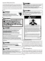
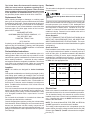
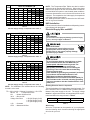
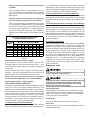
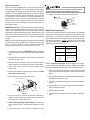
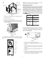
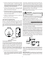
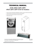
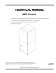
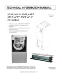
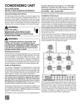
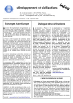
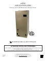
AEPF
AIR HANDLERS
INSTALLATION & OPERATING INSTRUCTIONS
®
C
US
RECOGNIZE THIS SYMBOL AS A SAFETY PRECAUTION.
ATTENTION INSTALLING PERSONNEL
Prior to installation, thoroughly familiarize yourself with this Installation Manual. Observe all safety warnings.
During installation or repair, caution is to be observed.
It is your responsibility to install the product safely and to educate the customer on its safe use.
IO-287G
6/2011
Goodman Manufacturing Company, L.P.
5151 San Felipe, Suite 500, Houston, TX 77056
www.goodmanmfg.com
© 2004-2011 Goodman Manufacturing Company, L.P.
CONTENTS
Important Safety Instructions ....................................... 3
Shipping Inspection ...................................................... 3
Codes & Regulations .................................................... 3
Replacement Parts ........................................................ 4
Pre-Installation Instructions ......................................... 4
Location ......................................................................... 4
Ductwork ........................................................................ 4
COOLING ONLY 2 STAGE HEAT THERMOSTAT ............................. 12
COOLING ONLY -2 STAGE HEAT
(1ST ROOM THERMOSTAT & 2ND OT ................. 12
COOLING ONLY 2 STAGE HEAT (THERMOSTAT ENABLED OT) .. 13
HEAT PUMP WITH 1 STAGE EMERGENCY HEAT,
1 STAGE AUXILIARY HEAT .................................. 13
HEAT PUMP - 2 STAGE EMERGENCY HEAT,
1 STAGE AUXILIARY HEAT .................................. 14
HEAT PUMP - 2 STAGE EMERGENCY HEAT,
2 STAGE AUXILIARY 1 OUTDOOR THERMOSTAT ................................. 14
HEAT PUMP - 2 STAGE EMERGENCY HEAT,
2 STAGE AUXILIARY 2 OUTDOOR THERMOSTATS ............................... 15
HEAT PUMP - 2 STAGE EMERGENCY HEAT,
1 STAGE AUXILIARY 1 OUTDOOR THERMOSTAT ................................. 15
HEAT PUMP - WITH 1 STAGE EMERGENCY HEAT,
1 STAGE AUXILIARY HEAT .................................. 16
HEAT PUMP - WITH 1 STAGE EMERGENCY HEAT,
1 STAGE AUXILIARY HEAT .................................. 16
HEAT PUMP - 2 STAGE EMERGENCY HEAT,
1 STAGE AUXILIARY HEAT .................................. 17
HEAT PUMP - 2 STAGE EMERGENCY HEAT,
2 STAGE AUXILIARY 1 OUTDOOR THERMOSTAT ................................. 17
HEAT PUMP - 2 STAGE EMERGENCY HEAT,
2 STAGE AUXILIARY 2 OUTDOOR THERMOSTATS ............................... 18
HEAT PUMP - 2 STAGE EMERGENCY HEAT 1 STAGE AUXILIARY 1 OUTDOOR THERMOSTAT ................................. 18
2 SPEED COOLING ONLY WITH 1 STAGE ELECTRIC HEAT ......................... 19
2 SPEED COOLING ONLY WITH 2 STAGE HEAT THERMOSTAT ................... 19
2 SPEED COOLING ONLY WITH 2 STAGE HEAT THERMOSTAT ................... 20
2 SPEED COOLING ONLY 2 STAGE HEAT (THERMOSTAT ENABLED OT) .. 20
WIRING DIAGRAM ....................................................... 21
Return Ductwork ......................................................... 4
Return Air Filters ......................................................... 4
Electric Heat .................................................................. 4
HKR Installation ............................................................. 5
Electrical Supply Wire and MOP .................................. 5
Building Electrical Service Inspection ...................... 5
Wire Sizing ................................................................... 6
Maximum Overcurrent Protection (MOP) .................. 6
Electrical Connections – Supply Voltage .................. 6
Air Handler Only (Non-Heat Kit Models) ............... 6
Air Handler With Non-Circuit Breaker Heat Kits .. 6
Air Handler With Heat Kits
Containing a Circuit Breaker ................................. 6
Low Voltage Connections ...................................... 6
Refrigerant Lines ........................................................... 6
Tubing Preparation ...................................................... 6
Post Brazing ................................................................ 6
Piping Size ................................................................... 7
Special Instructions .................................................... 7
Downflow Conversion .................................................. 7
Horizontal Conversion .................................................. 8
AEPF MOTOR ORIENTATION ....................................... 9
Condensate Removal .................................................... 9
ACHIEVING 2% LOW LEAKAGE RATE ...................... 10
AEPF Motor .................................................................. 10
Motor Speed Adjustment .......................................... 10
Dipswitch Functions ................................................. 10
CFM Delivery .............................................................. 10
Thermostat “Fan Only Mode” ................................... 10
CFM Trim Adjust ........................................................ 10
Humidity Control ....................................................... 10
Two Stage Heating .................................................... 10
Thermostats ................................................................. 11
Start-Up Procedure ..................................................... 11
Regular Maintenance .................................................. 11
THERMOSTAT CONNECTIONS .................................. 11
2
Important Safety Instructions
The following symbols and labels are used throughout this
manual to indicate immediate or potential safety hazards. It
is the owner’s and installer’s responsibility to read and comply with all safety information and instructions accompanying
these symbols. Failure to heed safety information increases
the risk of personal injury, property damage, and/or product
damage.
Do not connect to or use any device that is not designcertified by Goodman for use with this unit. Serious
property damage, personal injury, reduced unit
performance and/or hazardous conditions may result
from the use of such non-approved devices.
To prevent the risk of property damage, personal
injury, or death, do not store combustible materials or
use gasoline or other flammable liquids or vapors in
the vicinity of this unit.
HIGH VOLTAGE!
Disconnect ALL power before servicing.
Multiple power sources may be present.
Failure to do so may cause property damage,
personal injury or death.
CARBON MONOXIDE POISONING HAZARD
Special Warning for Installation of Furnace or Air Handling Units in
Enclosed Areas such as Garages, Utility Rooms or Parking Areas
Carbon monoxide producing devices (such as an automobile, space
heater, gas water heater, etc.) should not be operated in enclosed areas
such as unventilated garages, utility rooms or parking areas because of
the danger of carbon monoxide (CO) poisoning resulting from the exhaust
emissions. If a furnace or air handler is installed in an enclosed area such
as a garage, utility room or parking area and a carbon monoxide producing
device is operated therein, there must be adequate, direct outside
ventilation.
To avoid property damage, personal injury or death
due to electrical shock, this unit MUST have an
uninterrupted, unbroken electrical ground. The
electrical ground circuit may consist of an
appropriately sized electrical wire connecting the
ground lug in the unit control box to the building
electrical service panel.
Other methods of grounding are permitted if performed
in accordance with the National Electric Code
(NEC)/American National Standards Institute
(ANSI)/National Fire Protection Association (NFPA) 70
and local/state codes. In Canada, electrical grounding
is to be in accordance with the Canadian Electric Code
(CSA) C22.1.
This ventilation is necessary to avoid the danger of CO poisoning which
can occur if a carbon monoxide producing device continues to operate in
the enclosed area. Carbon monoxide emissions can be (re)circulated
throughout the structure if the furnace or air handler is operating in any
mode.
CO can cause serious illness including permanent brain damage or death.
B10259-216
-
Shipping Inspection
Always keep the unit upright; laying the unit on its side or top
may cause equipment damage. Shipping damage, and subsequent investigation is the responsibility of the carrier. Verify
the model number, specifications, electrical characteristics,
and accessories are correct prior to installation. The distributor or manufacturer will not accept claims from dealers for
transportation damage or installation of incorrectly shipped
units.
This product is factory-shipped for use with
208/240/1/60 electrical power supply. DO NOT
reconfigure this air handler to operate with any other
power supply.
Codes & Regulations
This product is designed and manufactured to comply with
national codes. Installation in accordance with such codes
and/or prevailing local codes/regulations is the responsibility of the installer. The manufacturer assumes no responsibility for equipment installed in violation of any codes or regulations.
When installing or servicing this equipment, safety
clothing, including hand and eye protection, is
strongly recommended. If installing in an area that has
special safety requirements (hard hats, etc.), Observe
these requirements.
3
The United States Environmental Protection Agency
(EPA) has issued various regulations regarding the introduction and disposal of refrigerants. Failure to follow
these regulations may harm the environment and can lead
to the imposition of substantial fines. Should you have
any questions please contact the local office of the EPA.
Ductwork
This air handler is designed for a complete supply and return
ductwork system.
Do not operate this product without all the ductwork
attached.
Replacement Parts
When reporting shortages or damages, or ordering repair
parts, give the complete product model and serial numbers
as stamped on the product. Replacement parts for this product are available through your contractor or local distributor.
For the location of your nearest distributor consult the white
business pages, the yellow page section of the local telephone book or contact:
CONSUMER AFFAIRS
GOODMAN MANUFACTURING COMPANY, L.P.
7401 SECURITY WAY
HOUSTON, TEXAS 77040
(877) 254-4729
To ensure correct system performance, the ductwork is to be
sized to accommodate 375-425 CFM per ton of cooling with
the static pressure not to exceed .5" WC. Inadequate duct
work that restricts airflow can result in improper performance
and compressor or heater failure. Ductwork is to be constructed in a manner that limits restrictions and maintains
suitable air velocity. Ductwork is to be sealed to the unit in a
manner that will prevent leakage.
Return Ductwork
DO NOT TERMINATE THE RETURN DUCTWORK IN AN
AREA THAT CAN INTRODUCE TOXIC, OR OBJECTIONABLE FUMES/ODORS INTO THE DUCTWORK. The return
ductwork is to be introduced into the air handler bottom (upflow
configuration).
If replacing an air handler, the system must be manufacturer
approved and Air Conditioning, Heating, and Refrigeration
Institute (AHRI) matched. NOTE: Installation of unmatched
systems is strongly discouraged.
Return Air Filters
Each installation must include a return air filter. This filtering
may be performed at the air handler or externally such as a
return air filter grille. Air handlers mounted in the downflow
orientation, including “B” series, require external filtering. A
washable filter is available as an accessory. To ensure optimum performance frequent filter cleaning is advised. Refer
to Table 1 for the appropriate filter.
Pre-Installation Instructions
Carefully read all instructions for the installation prior to installing product. Make sure each step or procedure is understood and any special considerations are taken into account
before starting installation. Assemble all tools, hardware
and supplies needed to complete the installation. Some items
may need to be purchased locally. Make sure everything
needed to install the product is on hand before starting.
Location
NOTE: Air handlers are designed for indoor installation
only.
Give special consideration to minimizing the length of refrigerant tubing when installing air handlers. Refer to Remote
Cooling/Heat Pump Service Manual, TP-106 Long Line Set
Application R-22 or TP-107 Long Line Set Application R-410A
for guidelines. The unit clearance from a combustible surface may be 0". However, service clearance is to take precedence. In addition allow a minimum of 24" in front of the unit
for service clearance.
If the unit is located in an area with high ambient temperature
and/or high humidity, the air handler may be subject to nuisance sweating of the casing. On these installations, a wrap
of 2” fiberglass insulation with a vapor barrier is recommended.
Do not install the air handler in a location that violates the
instructions provided with the condenser.
Consult all appropriate regulatory codes prior to determining
final clearances. When installing this unit in an area that may
become wet, elevate the unit with a sturdy, non-porous material. In installations that may lead to physical damage (i.e. a
garage) it is advised to install a protective barrier to prevent
such damage.
AEPF
Filter Number
Qty Required
N/A
FIL 18-32
1
1830
FIL 36-42
1
3036
3137
FIL 48-61
1
4260
Table 1
Electric Heat
Refer to this manual in combination with the instructions provided with the heat kit for the correct installation procedure.
The air handlers listed in this manual do not have factory
installed electric heat. Electric heat is available as an accessory. If installing this option, the ONLY heat kits that can be
used are the HKR series.
NOTE: The Amana® brand EHK, ECB, EDB, and EDK kits
are NOT approved for use with these air handlers.
4
The heating mode temperature rise is dependent upon the
system airflow, the supply voltage, and the heat kit size (kW)
selected. Use Tables 2, 3, and 4 to determine the temperature rise (ºF).
CFM
600
800
1000
1200
1400
1600
1800
2000
NOTE: The Temperature Rise Tables can also be used to
determine the air handler airflow delivery. When using these
tables for this purpose set the room thermostat to maximum
heat and allow the system to reach steady state conditions.
Insert two thermometers, one in the return air and one in the
supply air. The temperature rise is the supply air temperature
minus the room air temperature.
Use HKR specification sheets to determine the HKR available for a given air handler.
HEAT KIT NOMINAL kW
3
5
6
8
10
15
20
21
18
13
11
9
8
7
6
5
28
21
17
14
12
10
9
8
35
26
21
18
15
13
12
11
41
31
25
21
18
15
14
12
42
34
28
24
21
19
17
50
42
36
31
28
25
56
48
42
37
34
62
53
46
41
37
HKR Installation
Follow instructions listed in Installation and Operating Instructions shipped with the heat kit.
Table 2
230/1/60 Supply Voltage - Temperature Rise Table °F
CFM
600
800
1000
1200
1400
1600
1800
2000
3
5
17
13
10
8
7
6
6
5
27
20
16
13
11
10
9
8
HEAT KIT NOMINAL kW
6
8
10
15
20
34
25
20
17
14
13
11
10
39
30
24
20
17
15
13
12
40
32
27
23
20
18
16
48
40
34
30
27
24
53
46
40
36
32
Electrical Supply Wire and MOP
21
FIRE HAZARD!
To avoid the risk of property damage, personal injury
or fire, use only copper conductors.
59
51
44
39
35
HIGH VOLTAGE!
Disconnect ALL power before servicing.
Multiple power sources may be present.
Failure to do so may cause property damage,
personal injury or death.
Table 3
220/1/60 Supply Voltage - Temperature Rise Table °F
CFM
600
800
1000
1200
1400
1600
1800
2000
3
5
16
12
10
8
7
6
5
5
25
19
15
13
11
9
8
8
HEAT KIT NOMINAL kW
6
8
10
15
20
32
24
19
16
14
12
11
10
37
38
22
19
16
14
12
11
38
30
25
22
19
17
15
46
38
33
28
25
23
51
43
38
34
30
HIGH VOLTAGE!
To avoid property damage, personal injury or death
due to electrical shock, this unit MUST have an
uninterrupted, unbroken electrical ground. The
electrical ground circuit may consist of an
appropriately sized electrical wire connecting the
ground lug in the unit control box to the building
electrical service panel.
Other methods of grounding are permitted if performed
in accordance with the National Electric Code
(NEC)/American National Standards Institute
(ANSI)/National Fire Protection Association (NFPA) 70
and local/state codes. In Canada, electrical grounding
is to be in accordance with the Canadian Electric Code
(CSA) C22.1.
21
56
48
42
37
34
Table 4
208/1/60 Supply Voltage - Temperature Rise Table °F
Building Electrical Service Inspection
This unit is designed for single-phase electrical supply. DO
NOT OPERATE ON A THREE-PHASE POWER SUPPLY.
Measure the power supply to the unit. The supply voltage
must be in agreement with the unit nameplate power requirements and within the range shown in Table 5.
NOTE: For installations not indicated above the following
formula is to be used:
TR = (kW x 3412) x (Voltage Correction) x 1.08 / CFM
Where: TR
= Temperature Rise
kW
= Heater Kit Actual kW
3412 = Btu per kW
Voltage Correction
=.96 (230 Supply Volts)
=.92 (220 Supply Volts)
=.87 (208 Supply Volts)
1.08
= Constant
CFM = Measured Airflow
Nominal Input
208/240
Minimum Voltage
187
Maximum Voltage
253
Table 5
Wire Sizing
Wire size is important to the operation of your equipment.
Use the following check list when selecting the appropriate
wire size for your unit.
5
•
Wire size must carry the Minimum Circuit Ampacity (MCA).
•
Refer to the NEC (USA) or CSA (Canada) for wire sizing. The unit MCA for the air handler and the optional
electric heat kit can be found on the unit Series and
Rating Plate.
•
ity. A ground screw is also contained in this area. Attach the
supply wires to the air handler conductors as shown in the
unit wiring diagram using appropriately sized solderless connectors or other NEC or CEC approved means.
Air Handler With Non-Circuit Breaker Heat Kits
A terminal block is provided with the HKR kit to attach the
power supply and air handler connections. Follow the HKR
Installation Manual and wiring diagram for complete wiring
details.
Wire size allows for no more than a 2% voltage drop
from the building breaker/fuse panel to the unit.
Refer to the latest edition of the National Electric Code
or in Canada the Canadian Electric Code when determining the correct wire size. The following table shows
the current carrying capabilities for copper conductors
rated at 75oC with a 2% voltage drop. Use Table 6 to
determine the voltage drop per foot of various conductors.
Air Handler With Heat Kits Containing a Circuit Breaker
HKR models with a “C” suffix contain a circuit breaker(s).
The air handler has a plastic cover on the access panel that
will require either one or both sections to be removed to allow the heat kit circuit breaker(s) to be installed. See the
HKR Installation Instructions for further details. The air handler wires and supply wires are installed directly onto the HKR
circuit breaker(s) as shown in the HKR Installation Manual
and wiring diagram.
Maximum Allowable Length in Feet
to Limit Voltage Drop to 2%*
Wire Size
(AWG)
14
12
10
8
6
Low Voltage Connections
Several combinations of low voltage schemes are available,
depending on the presence of a heat kit and whether the
heat kit is single-stage or multi-staging. The low voltage connections are determined by whether the outdoor unit is a condenser or heat pump. The 24V-control voltage connects the
air handler to the room thermostat and condenser. Low voltage wiring is to be copper conductors. A minimum of 18AWG
must be used for installations up to 50’ and 16AWG for installations over 50’. Low voltage wiring can be connected
through the top of the cabinet or either side. See the “Thermostat Wiring” section of this manual for typical low voltage
wiring connections.
Minimum Circuit Ampacity (MCA)
10
75
118
188
301
471
15
50
79
125
201
314
20
37
59
95
150
235
25
NR
47
75
120
188
30
NR
NR
63
100
157
35
NR
NR
54
86
134
40
NR
NR
NR
75
118
45
NR
NR
NR
68
110
*Based on NEC 1996
Table 6
Maximum Overcurrent Protection (MOP)
Every installation must include an NEC (USA) or CEC
(Canada) approved overcurrent protection device. Also,
check with local or state codes for any special regional requirements.
Protection can be in the form of fusing or HACR style circuit
breakers. The Series and Rating Plate can be used as a
guide for selecting the MAXIMUM overcurrent device.
Refrigerant Lines
This product is factory-shipped under pressure. Follow
these instructions to prevent injury.
NOTE: Fuses or circuit breakers are to be sized larger
than the equipment MCA but not to exceed the MOP.
A quenching cloth is strongly recommended to prevent
scorching or marring of the equipment finish when
welding close to the painted surfaces. Use brazing
alloy of 5% minimum silver content.
Electrical Connections – Supply Voltage
USE COPPER CONDUCTORS ONLY.
A knockout is provided on the air handler top panel or side to
allow for the entry of the supply voltage conductors. If the
knockouts on the cabinet sides are used for electrical conduit, an adapter ring must be used in order to meet UL1995
safety requirements. An NEC or CEC approved strain relief
is to be used at this entry point. The wire is to be sized in
accordance with the “Electrical Wire and MOP” section of
this manual. Some areas require the supply wire to be enclosed in conduit. Consult your local codes.
Tubing Preparation
All cut ends are to be round, burr free, and clean. Failure
to follow this practice increases the chances for refrigerant
leaks. The suction line is spun closed and requires pipe
cutters to remove the closed end.
Post Brazing
Quench all welded joints with water or a wet rag.
Piping Size
For the correct tubing size, follow the specification for the
condenser/heat pump.
Air Handler Only (Non-Heat Kit Models)
The building supply connects to the stripped black and red
wires contained in the air handler electrical compartment cav-
6
Special Instructions
This coil comes equipped with a check style flowrator for
refrigerant management. For most installations with matching applications, no change to the flowrator piston is required.
However, in mix-matched applications, a flowrator piston
change may be required. See the Goodman® piston kit chart
or consult your local distributor for details regarding mixmatched piston sizing. If the mix-match application requires
a different piston size, change the piston in the flowrator on
the indoor coil before installing the coil and follow the procedure shown below.
Excessive torque can cause orifices to stick. Use the
proper torque settings when tightening orifices.
10. Replace suction line grommet and insulation.
SUCTION LINE
WITH SPIN CLOSURE
RUBBER
GROMMET
IMPORTANT NOTE: Torch heat required to braze tubes of
various sizes is proportional to the size of the tube. Tubes of
smaller size require less heat to bring the tube to brazing
temperature before adding brazing alloy. Applying too much
heat to any tube can melt the tube. Service personnel must
use the appropriate heat level for the size of the tube being
brazed.
NOTE: The use of a heat shield when brazing is recommended
to avoid burning the serial plate or the finish on the unit. Heat
trap or wet rags should be used to protect heat sensitive
components such as service valves and TXV valves.
Figure 2
Downflow Conversion
Conversion to downflow MUST be performed in an area that
allows access to all sides prior to placing the air handler in its
final location. To prevent the evaporator coil pan from “sweating” the DPI accessory insulation kit is to be used when performing this conversion. NOTE: The DPI kit is not supplied
with this product and is to be purchased separately. See
Table 7 for the correct DPI kit.
1. Loosen the 13/16 nut 1 TURN ONLY to allow high pressure tracer gas to escape. No gas indicates a possible
leak.
AEPF Model
Insulation Kit
N/A
DPI18-30/20
1830
DPI36-42/20
3036
DPI48-61/-20
3137
2. After the gas has escaped, remove the nut and discard
the black or brass cap.
4260
Table 7
3. Remove the check piston to verify it is correct and then
replace the piston. See piston kit chart in instructions.
Refer to Figures 3 through 5 for the location of the components referenced in the following steps. Figure 3 illustrates
the new installation location for the removed components.
4. Use a tube cutter to remove the spin closure on the
suction line.
1. Before inverting the air handler, remove all access panels, the coil rear channel bracket, and the filter close-off
panel.
5. Remove the tailpiece clamped to the exterior and slide
the 13/16 nut into place.
6. Braze tailpiece to the line set liquid tube.
2. Remove the evaporator coil and the horizontal drain pan.
Discard horizontal drain pan.
PLASTIC or BRASS CAP
3. Install the provided plastic plug into the vacated access
panel.
13/16” NUT
TAILPIECE
4. Remove the two (2) zee coil support brackets and insulation retaining brackets.
WHITE
TEFLON SEAL
5. Remove the tie bracket.
PISTON
6. Install the DPI Insulation Kit onto the bottom of the drain
pan.
Figure 1
7. Insert the suction line into the connection, slide the insulation and the rubber grommet at least 18" away from
the braze joint. Braze suction line.
8. AFTER THE TAILPIECE HAS COOLED, confirm position of the white Teflon® seal and hand tighten the 13/16”
nut.
9. Torque the 13/16” nut to 7-25 ft-lbs. or tighten 1/6 turn.
7
NOTE: When converted to downflow position the coil may
protrude above the cabinet on some models.
RETURN AIR SIDE
OF UNIT
REAR CHANNEL
BRACKET
ACCESS
PANEL
Horizontal Conversion
Dedicated Downflow models are not suitable for horizontal
application and must not be used for this type of installation.
The only field modification required for conversion to “Horizontal Right-Hand” is the removal of the plastic knockouts in
the horizontal panel drain connections. To prevent the horizontal drain pan from sweating in high humidity applications,
it is recommended that a DPIH insulation accessory kit be
used. NOTE: The DPIH insulation kit is not supplied with this
product and should be purchased separately. See Table 8
for the correct DPIH kit.
ZEE COIL
SUPPORT BRACKET
COIL RETAINING
BRACKET
TIE BRACKET
NOTE: The filter provision is not applicable
in THIS downflow application.
Figure 3
7. Install the zee coil supports and the wrapper stiffeners.
8. Install the tie bracket.
AEPF Model
Insulation Kit
N/A
DPIH18-32
1830
DPIH36-42
9. Install the rear channel bracket.
10. To prevent possible condensate “blow off” the insulation retainers are to be laid into the evaporator coil pan
as shown in Figure 4.
3036
DPIH48-61
3137
4260
Table 8
The following describes converting to “Horizontal Left-Hand”.
Conversion to downflow MUST be performed in an area that
allows access to all sides prior to placing the air handler in its
final location (See Figure 6).
3” FLAT INSULATION
RETAINER (BOTH SIDES)
Figure 4
To complete the conversion, slide the evaporator coil into
the chassis and attach the three (3) access panels. (Figure
5).
DPIH KIT
SECONDARY
DRAIN
PRIMARY
DRAIN
Figure 6
WRAPPER
1. Remove the (3) air handler access panels.
INSULATION
JACKET
2. Remove the “J” shaped bracket that retains the evaporator coil.
ZEE COIL
SUPPORT
3. Remove the flowrator from the lower left side access
panel and slide out the evaporator coil and horizontal
drain pan.
WRAPPER
STIFFENER
DRAIN PAN
INSULATION KIT
4. Remove the gasket from the horizontal pan drain connections.
BLOWER
ASSEMBLY
5. Remove the oval shaped plastic plug from the left side
access panel. Remove the oval shaped rubber gasket
seal from the lower right side access panel.
Figure 5
8
6. The drain connections for the horizontal pan are sealed
with a thin coating of plastic. Carefully knock out this
plastic seal with a screwdriver and hammer. Note: The
upper drain will become the secondary drain which
is mandatory in many municipalities .
A Secondary Condensate Drain Connection has been provided for areas where the building codes require it. Pitch the
drain line 1/4" per foot to provide free drainage. Insulate drain
lines located inside the building to prevent sweating. Install a
condensate trap to ensure proper drainage. If the secondary
drain line is required, run the line separately from the primary
drain and end it where it can be easily seen.
NOTE: Water coming from this line means the coil primary
drain is plugged and needs clearing.
7. Install the plastic plug removed in step 5 to the right
side lower access panel and the oval shaped rubber
gasket to the lower left access panel.
8. Reinstall the evaporator coil with the horizontal panel
on the left side. Note: Push the assembly completely to
the rear to ensure the engagement of the upflow pan
with the rear channel bracket.
CAUTION
If secondary drain is not installed, the secondary
access must be plugged.
9. Install the “J” bracket (removed in step 2) to support the
upflow pan to the tie channel.
The installation must include a “P” style trap that is located
as close as is practical to the evaporator coil. See Figure 7
for details of a typical condensate line “P” trap.
NOTE: Trapped lines are required by many local codes. In
the absence of any prevailing local codes, please refer to the
requirements listed in the Uniform Mechanical Building Code.
A drain trap in a draw-through application prevents air from
being drawn back through the drain line during fan operation
thus preventing condensate from draining, and if connected
to a sewer line to prevent sewer gases from being drawn into
the airstream during blower operation.
Field experience has shown condensate drain traps with an
open vertical Tee between the air handler and the condensate drain trap can improve condensate drainage in some
applications,but may cause excessive air discharge out of
the open Tee. Goodman® does not prohibit this type of drain
but we also do not recommend it due to the resulting air leakage. Regardless of the condensate drain design used, it is
the installer’s responsibility to ensure the condensate drain
system is of sufficient design to ensure proper condensate
removal from the coil drain pan.
10. Attach all panels and the metering device.
AEPF MOTOR ORIENTATION
If the unit is in the upflow position, there is no need to rotate
the motor. If the unit is in the downflow position, loosen motor mount and rotate motor as shown in Figure 7. Be sure
motor is oriented with the female connections on the casing
down. If the motor is not oriented with the connections down,
water will collect in the motor and may cause premature failure.
Drain
Connection
FEMALE
CONNECTIONS
Figure 7
(AEPF Motor Orientation)
Air Handler
2" MIN.
Condensate Removal
The coil drain pan has a primary and a secondary drain with
3/4" NPT female connections. The connectors required are
3/4" NPT male, either PVC or metal pipe, and should be hand
tightened to a torque of approximately 37 in-lbs. to prevent
damage to the drain pan connection. An insertion depth between .355 to .485 inches (3-5 turns) should be expected at
this torque. Use the female (3/4 NPT) threaded fitting that
protrudes outside of the enclosure for external connections.
POSITIVE LIQUID
SEAL REQUIRED
AT TRAP
3" MIN.
Figure 8
Use of a condensate removal pump is permitted when necessary. This condensate pump should have provisions for
shutting off the control voltage should a blocked drain occur.
A trap must be installed between the unit and the condensate pump.
1. Ensure drain pan hole is NOT obstructed.
2. To prevent potential sweating and dripping on to finished
space, it may be necessary to insulate the condensate
drain line located inside the building. Use Armaflex® or
similar material.
IMPORTANT NOTE: The evaporator coil is coated with oils
that may dissolve styrofoam and certain types of plastics.
Therefore, a removal pump or float switch must not contain
any of these materials.
9
CFM Delivery
Tables 10-Electric Heat and 11-Cooling/Heat Pump show
the CFM output for dipswitch combinations 1-2, and 5-6.
Tip: Priming the “P” trap may avoid improper draining at the
initial installation and at the beginning of the cooling season.
When coils are installed above ceilings, or in other locations
where damage from condensate overflow may occur, it is
MANDATORY to install a field fabricated auxiliary drain pan
under the coil cabinet enclosure. Drain lines from the auxiliary pan must be installed and terminated so that the homeowner can see water discharges.
Switch
Model
AEPF1830
2
7
8
OFF
OFF
OFF
1210
ON
OFF
OFF
OFF
890
935
ON
OFF
OFF
700
770
OFF
OFF
OFF
OFF
2050
2150
AEPF3036
ON
OFF
OFF
OFF
1750
1835
AEPF3137
OFF
ON
OFF
OFF
1600
1680
AEPF4260
ON
ON
OFF
OFF
1200
1260
ON
ON
OFF
ON
1020
1070
Switch
CFM
8
Nominal
Cooling
Tonnage
Switch
Model
This section references the operation characteristics of the
AEPF model motor only. The ECM control board is factory
set with dipswitch #4 in the “ON” position and all other
dipswitches in the “OFF” position. For most applications
this setting is to be changed according to the electric
heat size and the outdoor unit selection.
The AEPF product uses a General Electric ECMTM motor.
This motor provides many features not available on the traditional PSC motor. These features include:
• Improved Efficiency
• Constant CFM
• Soft Start and Stop
• Improved Humidity Control
Motor Speed Adjustment
Each ECMTM blower motor has been preprogrammed for operation at 4 distinct airflow levels when operating in Cooling,
H.P. Heating, Backup Heating (Electric Heating), and Backup
+ H.P. Heating. Each mode has 4 levels to deliver different
Air Flow CFM [L/s]. The adjustment is performed by changing the dipswitch(es) either to an “OFF” or “ON” position.
5
AEPF1830
6
7
OFF
OFF
OFF
OFF
2½
1100
ON
OFF
OFF
OFF
2
800
OFF
ON
OFF
OFF
1½
600
OFF
OFF
OFF
OFF
5
1800
AEPF3036
ON
OFF
OFF
OFF
4
1580
AEPF3137
OFF
ON
OFF
OFF
3½
1480
AEPF4260
ON
ON
OFF
OFF
3
1200
ON
ON
OFF
ON
2½
1020
Table 11
Thermostat “Fan Only Mode”
During “Fan Only Mode” operation, the CFM output is 30% of
the cooling setting.
CFM Trim Adjust
Minor adjustments can be made through the dip switch combination of 7-8. The following Table 12 shows the switch
position for this feature.
Dipswitch Functions
The AEPF air handler motor has an electronic control that
contains an eight (8) position dip switch. The function of these
dipswitches are shown in Table 9.
Dipswitch Number
1100
Table 10
AEPF Motor
1
2
3
4
5
6
7
8
1
OFF
Emergecny Heat Pump
(Electric)
w/Backup
Heat
Heat
OFF
ACHIEVING 2% LOW LEAKAGE RATE
Ensure that the Neoprene gasket with PSA remains intact on
all surfaces that the access panels are secured to. These
surfaces are the entire length of the wrapper and areas between the upper tie plate, upper and lower access panels.
Be sure that upper access panel breaker insert gasket is intact and also flowrator gasket is installed on the lower access panel. An additional drain hole cover is required.
Switch
CFM
Switch 7
Switch 8
+10%
-15%
ON
OFF
OFF
ON
Table 12
Function
Humidity Control
When using a Humidistat (normally closed), cut jumper PJ6
on the control board. The Humidistat will only affect cooling
airflow by adjusting the Airflow to 85%.
Electric Heat
N/A
Indoor Thermostat
Two Stage Heating
When using staged electric heat, cut jumper PJ4 on the control board.
Cooling & Heat Pump CFM
CFM Trim Adjust
Table 9
10
Thermostats
NOTE: THESE INSTRUCTIONS ARE SPECIFICALLY FOR
AEPF MODELS. DO NOT USE THESE DIAGRAMS FOR ANY
OTHER MODELS. SEE SEPARATE INSTALLATION AND
OPERATING INSTRUCTIONS FOR ATUF, ARUF, ARPT,
ADPF, AND ASPF MODELS.
NOTE: Second Stage heat can be accomplished by multistage heating thermostat or the addition of an outdoor
thermostat as shown in Figures 9 and 10.
Goodman® part number CHT18-60 is a single-stage cool and
single-stage heat thermostat.
Goodman® part number HPT18-60 is a single-stage cool,
two-stage heat pump thermostat. The first stage is heat pump
heating and the second stage is optional electric heat.
If additional features are desired, such as digital or programmable capabilities, these thermostats are commercially available. Follow the thermostat manufacturer’s instruction for installation.
NOTICE: THIS PRODUCT CONTAINS ELECTRONIC
COMPONENTS WHICH REQUIRE A DEFINITE
GROUND. PROVISIONS ARE MADE FOR CONNECTION OF THE GROUND. A DEDICATED GROUND
FROM THE MAIN POWER SUPPLY OR AN EARTH
GROUND MUST BE PROVIDED.
THERMOSTAT CONNECTIONS
Start-Up Procedure
•
Prior to start-up, ensure that all electrical connections
are properly sized and tightened.
•
All panels must be in place and secured. For Air Tight
application, neoprene gasket must be positioned at prescribed locations to achieve 2% leakage.
•
Tubing must be leak free.
•
Unit should be elevated, trapped and pitched to allow
for drainage.
•
Low voltage wiring is connected.
•
Auxiliary drain is installed when necessary and pitched
to allow for drainage.
•
Drain pan and drain tubing has been leak checked.
•
Return and supply ducts are sealed.
•
Unit is elevated when installed in a garage or where
flammable vapors may be present.
•
Unit is protected from vehicular or other physical damage.
•
Return air is not obtained from any areas where there
may be objectionable odors, flammable vapors or products of combustion such as carbon monoxide (CO),
which may cause serious personal injury or death.
The following composite wiring diagrams detail various configurations in which the AEPF air handlers can be used. Examples include single-stage cooling and heat pump with single
or two-stage electric heating. All these configurations can
be applied with convenient connections to outdoor thermostat applications.
The following sections will be detailed:
•
Single-Stage Cooling (GMC Thermostat Part #CHT1860 or equivalent.)
•
Heat Pump (GMC Thermostat Part #18-60 or equivalent)
Each diagram details the connections between room thermostat and AEPF air handlers, and the connections between
the AEPF air handlers and the Condensing Unit (or Heat
Pump) with optional connections to Outdoor Thermostats.
For each configuration, refer to the explanation of the proper
jumper(s) to remove for the corresponding blower speed that
will result in the programmed ECM™ motor.
IMPORTANT: WHEN MATCHING THE AEPF AIR
HANDLER TO A SINGLE SPEED COOLING UNIT OR
HEAT PUMP REMEMBER TO CONNECT THE “Y”
FROM THE THERMOSTAT TO THE “Y/Y2” CONNECTION ON THE VARIABLE SPEED BOARD (VSTB) OF
THE AIR HANDLER. CONNECTING TO “Y1” WILL
RESULT IN FIRST STAGE COOLING BLOWER
SPEED AND MAY CAUSE THE CONTACTOR TO
CHATTER.
Regular Maintenance
An equivalent thermostat can be used in place of the
Goodman thermostat part number. The GMC thermostats
listed are mercury type thermostats.
HIGH VOLTAGE!
Disconnect ALL power before servicing or
installing this unit. Multiple power sources may
be present. Failure to do so may cause property
damage, personal injury or death.
The only item to be maintained on a regular basis by the user
is the circulating air filter(s). Filter should be cleaned or replaced regularly. A certified service technician must perform
all other services.
11
WARNING
HIGH VOLTAGE! DISCONNECT ALL POWER BEFORE SERVICING.
MULTIPLE POWER SOURCES MAY BE PRESENT. FAILURE TO DO SO
MAY CAUSE PROPERTY DAMAGE, PERSONAL INJURY OR DEATH.
SINGLE STAGE COOLING WITH SINGLE OR TWO-STAGE HEATING
ROOM
THERMOSTAT
FIGURE 9
W1
R
C
W2
G
Y
IF NEEDED
FOR HEAT PUMP
USE ONLY
O
CONDENSING
UNIT
NOTES:
1.) Y/Y2 ENABLES HI SPD FAN COOLING
HUMIDISTAT
(OPTIONAL)
THERMOSTATS
OTC OT1 OT2
C
E\W1 W/W2
O
YCON COM
HEATPUMP
O
W2
ED
R
Y1
G
Y/Y2
HUMIDISTAT
HUM
2.) E/W1 ENABLES LO SPD FAN HEATING
W/W2 ENABLES HI SPD FAN HEATING
OUTDOOR
3.) OT1 PJ4 MUST BE CUT FOR THIS CONFIGURATION
R
4.) DIP SWITCH #4 MUST BE IN THE "ON" POSITION.
Y1
W1 W2
HEATER
W1
SWITCH
5.) CUT HUM PJ6 JUMPER IF USING HUMIDISTAT.
STAT OPENS ON HUMIDITY RISE.
C
R
24 VAC
W2
OT1
OT2
ON
OFF
DIP
HUM
PLEASE REFER
TO MANUAL
FOR PROPER
DIP SWITCH(CFM)
CONFIGURATION.
COOLING ONLY - 2 STAGE HEAT THERMOSTAT
ROOM
THERMOSTAT
FOR HEAT PUMP
USE ONLY
W
CONDENSING
UNIT
NOTES:
1.) Y/Y2 ENABLES HI SPD FAN COOLING
G
Y
HUMIDISTAT
(OPTIONAL)
THERMOSTATS
E\W1 W/W2
O
OTC OT1
2.) E/W1 ENABLES LO SPD FAN HEATING
E/W1 WITH OT CLOSED ENABLES HI SPD FAN HEATING
OT2
Y1
G
Y/Y2
HUMIDISTAT
HUM
OUTDOOR
HEATPUMP
CONDENSER
YCON COM
O
W2
Y1
ED
4.) DIP SWITCH #4 MUST BE IN THE "ON" POSITION.
W1 W2
HEATER
W1
5.) CUT HUM PJ6 JUMPER IF USING HUMIDISTAT.
STAT OPENS ON HUMIDITY RISE.
OT1
OT2
W2
24 VAC
SWITCH
3.) OT1 PJ4 MUST BE CUT FOR THIS CONFIGURATION
R
C
IF NEEDED
O
FIGURE 10
OFF
ON
PLEASE REFER
TO MANUAL
FOR PROPER
DIP SWITCH(CFM)
CONFIGURATION.
DIP
HUM
COOLING ONLY - 2 STAGE HEAT (1st ROOM T'STAT & 2nd OT)
Wiring is subject to change, always refer to the wiring diagram on the unit for the most up-to-date wiring.
12
HIGH VOLTAGE! DISCONNECT ALL POWER BEFORE SERVICING.
MULTIPLE POWER SOURCES MAY BE PRESENT. FAILURE TO DO SO
MAY CAUSE PROPERTY DAMAGE, PERSONAL INJURY OR DEATH.
WARNING
ROOM
THERMOSTAT
FOR HEAT PUMP
USE ONLY
O
C
W2
R
G
Y
IF NEEDED
W1
CONDENSING
UNIT
NOTES:
1.) Y/Y2 ENABLES HI SPD FAN COOLING
HUMIDISTAT
(OPTIONAL)
THERMOSTATS
OTC OT1 OT2
E\W1 W/W2
O
CONDENSER
HEATPUMP
O
W2
ED
Y1
G
Y/Y2
HUMIDISTAT
HUM
2.) E/W1 ENABLES LO SPD FAN HEATING
W/W2 WITH OT CLOSED ENABLES HI SPD FAN HEATING
OUTDOOR
3.) OT1 PJ4 MUST BE CUT FOR THIS CONFIGURATION
OT2 PJ2 MUST BE CUT FOR THIS CONFIGURATION
YCON COM
Y1
4.) DIP SWITCH #4 MUST BE IN THE "ON" POSITION.
W1 W2
HEATER
W2
W1
24 VAC
SWITCH
5.) CUT HUM PJ6 JUMPER IF USING HUMIDISTAT.
STAT OPENS ON HUMIDITY RISE.
OT1
OT2
ON
PLEASE REFER
TO MANUAL
FOR PROPER
DIP SWITCH (CFM)
CONFIGURATION.
OFF
DIP
HUM
COOLING ONLY - 2 STAGE HEAT (T'STAT ENABLED OT)
HEAT PUMP WITH SINGLE OR TWO-STAGE HEATING (OPTIONS FOR EMERGENCY HEAT)
ROOM
THERMOSTAT
HEATPUMP
R
Y
C
O
E
W2
O
W2
R
C
G
Y
HUMIDISTAT
(OPTIONAL)
HEATPUMP
YCON COM
O
W2
ED
IF NEEDED
R
THERMOSTATS
E\W1 W/W2
O
OTC OT1
NOTES:
1.) Y ENABLES HI SPD FAN COOLING
OT2
C
R
Y1
G
Y/Y2
HUMIDISTAT
HUM
OUTDOOR
REMOVE
PRODUCTION
WIRE Y1-O
HEATPUMP
YCON COM
O
W2
3.) IF OT2 PJ2 JUMPER IS CUT E AND W2 ENABLE
LO SPD FAN HEATING
OT1
5.) CUT HUM PJ6 JUMPER IF USING HUMIDISTAT.
STAT OPENS ON HUMIDITY RISE.
HUM
OT2
PLEASE REFER
TO MANUAL
FOR PROPER
DIP SWITCH(CFM)
CONFIGURATION.
C
R
24 VAC
DIP
4.) DIP SWITCH #4 MUST BE IN THE "ON" POSITION.
W2
SWITCH
W1 W2
HEATER
W1
6.) REMOVE ORANGE JUMPER WIRE Y1-O.
Y1
ED
OFF
R
ON
2.) E AND W2 ENABLE HI SPD FAN HEATING
HEATPUMP - WITH 1 STG EMHT 1 STG AUX HEAT
Wiring is subject to change, always refer to the wiring diagram on the unit for the most up-to-date wiring.
13
WARNING
HIGH VOLTAGE! DISCONNECT ALL POWER BEFORE SERVICING.
MULTIPLE POWER SOURCES MAY BE PRESENT. FAILURE TO DO SO
MAY CAUSE PROPERTY DAMAGE, PERSONAL INJURY OR DEATH.
ROOM
THERMOSTAT
HEATPUMP
R
Y
C
YCON COM
O
E
W2
O
W2
R
C
G
Y
IF NEEDED
R
HEATPUM P
O
W2
ED
HUMIDISTAT
(OPTIONAL)
THERMOSTATS
E\W 1 W/W2
O
OTC OT1
YCON COM
HEATPUM P
O
W2
ED
NOTES:
1.) Y ENABLES HI SPD FAN COOLING
OT2
C
R
Y1
G
Y/Y2
HUMIDISTAT
HUM
OUTDOOR
R
W1 W2
HEATER
3.) OT1 PJ4 MUST BE CUT FOR THIS CONFIGURATION
W1
C
R
24 VAC
OT2
PLEASE REFER
TO MANUAL
FOR PROPER
DIP SW ITCH(C FM)
CONFIG URATION.
OFF
DIP
HUM
ON
6.) REMOVE ORANGE JUMPER WIRE Y1-O.
W2
OT1
4.) DIP SWITCH #4 MUST BE IN THE "ON" POSITION.
5.) CUT HUM PJ6 JUMPER IF USING HUMIDISTAT.
STAT OPENS ON HUMIDITY RISE.
Y1
SWITCH
2.) E ENABLES LO SPD FAN HEATING
W2 ENABLES HI SPD FAN HEATING
REMOVE
PRODUCTION
WIRE Y1-O
HEATPUMP - 2 STG EMHT 1 STG AUX HEAT
OUTDOOR
THERMOSTAT
W2
IF NEEDED
W2
O
E\W1 W/W2
O
G
Y/Y2
REMOVE
PRODUCTION
WIRE Y1-O
ON
5.) CUT HUM PJ6 JUMPER IF USING HUMIDISTAT.
STAT OPENS ON HUMIDITY RISE.
DIP
4.) DIP SWITCH #4 MUST BE IN THE "ON" POSITION.
OFF
SWITCH
O
DIP SWITCH
6.) REMOVE ORANGE JUMPER WIRE Y1-O.
2nd STAGE HEATER
1st STAGE HEATER
1st STAGE AUX HEAT ENABLED BY ROOM T'STAT
2ND STAGE AUX ENABLED BY ROOM T'STAT AND OUTDOOR T'STAT
HEATPUMP - 2 STG EMHT 2 STG AUX - 1 OUTDOOR T'STAT
Wiring is subject to change, always refer to the wiring diagram on the unit for the most up-to-date wiring.
14
WARNING
HIGH VOLTAGE! DISCONNECT ALL POWER BEFORE SERVICING.
MULTIPLE POWER SOURCES MAY BE PRESENT. FAILURE TO DO SO
MAY CAUSE PROPERTY DAMAGE, PERSONAL INJURY OR DEATH.
ROOM
THERMOSTAT
HEATPUMP
R
Y
C
YCON COM
O
E
W2
O
W2
C
R
G
Y
IF NEEDED
R
HEATPUMP
O
W2 ED
OTC OT1
HUMIDISTAT
(OPTIONAL)
OT2
OUTDOOR
THERMOSTATS
E\W1 W/W2
O
YCON COM
HEATPUMP
O
W2
ED
NOTES:
1.) Y ENABLES HI SPD FAN COOLING
OTC OT1
C
R
Y1
G
Y/Y2
HUMIDISTAT
HUM
OUTDOOR
R
2.) E ENABLES LO SPD FAN HEATING
W2 AND OT1 CLOSED ENABLES LO SPD FAN HEATING
W2 AND OT2 CLOSED ENABLES HI SPD FAN HEATING
REMOVE
PRODUCTION
WIRE Y1-O
Y1
W1 W2
HEATER
C
R
24 VAC
SWITCH
W1
3.) OT1 PJ4 AND 0T2 PJ2 MUST BE CUT
FOR THIS CONFIGURATION
OT2
W2
OT1
OT2
5.) CUT HUM PJ6 JUMPER IF USING HUMIDISTAT.
STAT OPENS ON HUMIDITY RISE.
OFF
PLEASE REFER
TO MANUAL
FOR PROPER
DIP SWITCH(CFM)
CONFIGURATION.
ON
4.) DIP SWITCH #4 MUST BE IN THE "ON" POSITION.
DIP
HUM
6.) REMOVE ORANGE JUMPER WIRE Y1-O.
HEATPUMP - 2 STG EMHT 2 STG AUX - 2 OUTDOOR T'STATS
R
C
O
O
C
R
G
W2
E\W1 W/W2
REMOVE
PRODUCTION
WIRE Y1-O
W2
W1
W1
W2
W2
ON
4.) DIP SWITCH #4 MUST BE IN THE "ON" POSITION.
5.) CUT HUM PJ6 JUMPER IF USING HUMIDISTAT.
STAT OPENS ON HUMIDITY RISE.
6.) REMOVE ORANGE JUMPER WIRE Y1-O.
Wiring is subject to change, always refer to the wiring diagram on the unit for the most up-to-date wiring.
15
WARNING
HIGH VOLTAGE! DISCONNECT ALL POWER BEFORE SERVICING.
MULTIPLE POWER SOURCES MAY BE PRESENT. FAILURE TO DO SO
MAY CAUSE PROPERTY DAMAGE, PERSONAL INJURY OR DEATH.
2 SPEED HEAT PUMP WITH SINGLE OR TWO STAGE HEATING
(OPTIONS FOR EMERGENCY HEAT) WITH CONVENTIONAL TWO STAGE THERMOSTAT
ROOM
THERMOSTAT
HEATPUMP
W2
O
IF NEEDED
W2
HEATPUMP
COM
HUMIDISTAT
(OPTIONAL)
W2
SEE NOTE 4
E\W1 W/W2
HUMIDISTAT
Y/Y2 HUM
THERMOSTATS
OTC OT1 OT2
O
NOTES:
1.) Y ENABLES HI SPD FAN COOLING
REMOVE
PRODUCTION
WIRE Y1-O
OUTDOOR
HEATPUMP
2.) E ENABLES LO SPD FAN HEATING
W2
1
5
COM
W1
W2
PJ2
PJ6
5.) DIP SWITCH #4 MUST BE IN THE "OFF" POSITION
PN. B1368274
J1
6.) REMOVE ORANGE JUMPER WIRE Y1-O.
DI
P
J3
OT2
HUM
J2
PJ4
4
OT1
1
4.) CUT HUM PJ6 JUMPER IF USING HUMIDISTAT
STAT OPENS ON HUMIDITY RISE
W2
1 2 3 4 5 67 8
24 VAC
W1
GOODMAN MFG. CO. L.P.
2nd STAGE HEATER
1ST STAGE HEATER
HEATPUMP - WITH 1 STG EMHT 1 STG AUX HEAT
Y2
C
CONDENSER
R
YCON COM
O
W2
E
Y1
O
W2
HEATPUMP
O
W2
C
R
G
Y2
R
Y1
G
Y1
IF NEEDED
R
ED
O
E\W1 W/W2
THERMOSTATS
OTC OT1 OT2
C
Y/Y2
HUMIDISTAT
HUM
OUTDOOR
HEATPUMP
O
W2
ED
CONDENSER
YCON COM
Y1
1
5
R
REMOVE
PRODUCTION
WIRE Y1-O
1 2 3 4 5 67 8
O
N
4
J3
J2
1
DS1
O
FF
CR1
R1
R3
J1
CR2
DI
P
CR5
PJ6
C2
R2
CR10
HUM
PLEASE REFER
TO MANUAL
FOR PROPER
DIP SWITCH
CONFIGURATION.
CR6
PJ2
CR7
CR9
PJ4
OT2
CR8
OT1
R
C
24 VAC
W2
S
WI
TC
H
CR11
W1
W2
CR3
W1
HEATPUMP - WITH 1 STG EMHT 1 STG AUX HEAT
Wiring is subject to change, always refer to the wiring diagram on the unit for the most up-to-date wiring.
16
WARNING
O
Y1
E
O
W2
C
HEATPUMP
CONDENSER
YCON COM
O
W2
R
G
Y2
R
Y1
G
Y1
ED
THERMOSTATS
OTC OT1 OT2
C
O
E\W1 W/W2
Y/Y2
HUMIDISTAT
HUM
OUTDOOR
HEATPUMP
O
W2
ED
CONDENSER
YCON COM
Y1
1
5
R
REMOVE
PRODUCTION
WIRE Y1-O
1 2 3 4 5 67 8
J3
J2
4
1
DS1
O
FF
O
N
R3
J1
R1
DI
P
CR1
PJ6
CR2
HUM
PLEASE REFER
TO MANUAL
FOR PROPER
DIP SWITCH
CONFIGURATION.
CR5
PJ2
C2
R2
CR10
PJ4
OT2
R
C
24 VAC
CR6
CR9
OT1
W2
S
WI
TC
H
CR7
W1
W2
CR11
W1
CR8
HEATPUMP - 2 STG EMHT 1 STG AUX HEAT
Y2
C
O
CONDENSER
YCON COM
Y1
E
O
W2
C
R
G
Y2
R
Y1
G
Y1
HEATPUMP
O
W2
ED
E\W1 W/W2
O
THERMOSTATS
OTC OT1 OT2
C
Y/Y2
HUMIDISTAT
HUM
OUTDOOR
HEATPUMP
O
W2
ED
CONDENSER
Y1
1
5
R
YCON COM
REMOVE
PRODUCTION
WIRE Y1-O
1 2 3 4 5 67 8
O
FF
J3
J2
4
1
DS1
R1
R3
J1
O
N
CR1
DI
P
CR2
PJ6
CR5
HUM
PLEASE REFER
TO MANUAL
FOR PROPER
DIP SWITCH
CONFIGURATION.
CR6
CR10
PJ4
PJ2
C2
R2
W2
OT2
CR7
CR9
W1
OT1
R
C
24 VAC
W2
S
WI
TC
H
CR8
W1
CR11
R
W2
IF NEEDED
R
CR3
R
W2
IF NEEDED
C
Y2
CR3
R
HIGH VOLTAGE! DISCONNECT ALL POWER BEFORE SERVICING.
MULTIPLE POWER SOURCES MAY BE PRESENT. FAILURE TO DO SO
MAY CAUSE PROPERTY DAMAGE, PERSONAL INJURY OR DEATH.
HEATPUMP - 2 STG EMHT 2 STG AUX - 1 OUTDOOR T'STAT
Wiring is subject to change, always refer to the wiring diagram on the unit for the most up-to-date wiring.
17
WARNING
O
CONDENSER
YCON COM
Y1
E
O
W2
C
R
G
Y2
R
Y1
G
Y1
HEATPUMP
O
W2
ED
OTC OT1
OT2
OUTDOOR
THERMOSTATS
C
OTC OT1 OT2
O
E\W1 W/W2
Y/Y2
HUMIDISTAT
HUM
REMOVE
PRODUCTION
WIRE Y1-O
OUTDOOR
HEATPUMP
O
W2
ED
CONDENSER
YCON COM
Y1
1
5
R
R3
J1
1 2 3 4 5 67 8
O
FF
O
N
J3
J2
4
1
DS1
R1
DI
P
CR1
PJ6
CR2
HUM
PLEASE REFER
TO MANUAL
FOR PROPER
DIP SWITCH
CONFIGURATION.
CR5
R2
CR10
PJ2
CR6
PJ4
OT2
CR7
OT1
R
C
24 VAC
W2
S
WI
TC
H
W2
C2
W1
CR9
W1
CR8
HEATPUMP - 2 STG EMHT 2 STG AUX - 2 OUTDOOR T'STATS
C
CONDENSER
YCON COM
W2
Y1
E
O
W2
HEATPUMP
O
W2
C
R
G
Y2
R
Y1
G
Y1
ED
O
E\W1 W/W2
THERMOSTATS
OTC OT1 OT2
C
Y/Y2
HUMIDISTAT
HUM
OUTDOOR
HEATPUMP
O
W2
ED
CONDENSER
YCON COM
Y1
1
5
R
REMOVE
PRODUCTION
WIRE Y1-O
R3
J1
1 2 3 4 5 67 8
O
N
O
FF
4
J3
J2
1
DS1
R1
DI
P
CR1
PJ6
CR2
HUM
PLEASE REFER
TO MANUAL
FOR PROPER
DIP SWITCH
CONFIGURATION.
CR5
CR10
PJ4
PJ2
CR6
R2
W2
OT2
R
C
24 VAC
C2
CR9
W1
OT1
W2
S
WI
TC
H
CR7
W1
CR8
R
O
IF NEEDED
Y2
CR11
R
CR3
R
W2
IF NEEDED
C
CR11
Y2
CR3
R
HIGH VOLTAGE! DISCONNECT ALL POWER BEFORE SERVICING.
MULTIPLE POWER SOURCES MAY BE PRESENT. FAILURE TO DO SO
MAY CAUSE PROPERTY DAMAGE, PERSONAL INJURY OR DEATH.
HEATPUMP - 2 STG EMHT 1 STG AUX - 1 OUTDOOR T'STAT
Wiring is subject to change, always refer to the wiring diagram on the unit for the most up-to-date wiring.
18
HIGH VOLTAGE! DISCONNECT ALL POWER BEFORE SERVICING.
MULTIPLE POWER SOURCES MAY BE PRESENT. FAILURE TO DO SO
MAY CAUSE PROPERTY DAMAGE, PERSONAL INJURY OR DEATH.
WARNING
TWO-STAGE COOLING WITH CONVENTIONAL TWO-STAGE THERMOSTAT
ROOM
THERMOSTAT
FOR HEAT PUMP
USE ONLY
O
C
W
2-SPD
CONDENSING
UNIT
N
E
E
D
E
D
C
HUMIDISTAT
(OPTIONAL)
SEE NOTE 4
NOTES:
1.) Y1 ENABLES LO SPD FAN COOLING
Y/Y2 ENABLES HI SPD FAN COOLING
E W1 W/W2
O
THERMOSTATS
OTC OT1 OT2 C
2.) E/W1 ENABLES HI SPD FAN HEATING
R
Y1
G
HUMIDISTAT
Y/Y2 HUM
OUTDOOR
3.) IF OT1 PJ4 JUMPER IS CUT E/W1 ENABLES
LOW SPD FAN HEATING
R
CONDENSER HEATPUMP
YCON COM O
W2 ED
4.) CUT HUM PJ6 JUMPER IF USING HUMIDISTAT
STAT OPENS ON HUMIDITY RISE
W1
5.) DIP SWITCH #4 MUST BE IN THE “OFF” POSITION
OT1
OT2
W2
Y1
W1 W2
HEATER
S
WI
T
C
H
HUM
DI
P
PLEASE REFER
TO MANUAL
FOR PROPER
DIP SWITCH(CFM)
CONFIGURATION.
C
R
24 VAC
O
N
O
FF
1st STAGE HEATER
2 SPD COOLING ONLY - WITH 1 STAGE ELECTRIC HEAT
ROOM
THERMOSTAT
FOR HEAT PUMP
USE ONLY
W
O
C
C
IF
2-SPD
CONDENSING
UNIT
HUMIDISTAT
(OPTIONAL)
Y2
NOTES:
1.) Y1 ENABLES LO SPD FAN COOLING
Y/Y2 ENABLES HI SPD FAN COOLING
Y1
SEE NOTE 4
\
2.) E/W1 ENABLES HI SPD FAN HEATING
3.) IF OT1 PJ4 JUMPER IS CUT E/W1 ENABLES
LOW SPD FAN HEATING
4.) CUT HUM PJ6 JUMPER IF USING HUMIDISTAT
STAT OPENS ON HUMIDITY RISE
5.) DIP SWITCH #4 MUST BE IN THE “OFF” POSITION
1st STAGE HEATER
2 SPD COOLING ONLY - WITH 2 STAGE HEAT THERMOSTAT
Wiring is subject to change, always refer to the wiring diagram on the unit for the most up-to-date wiring.
19
HIGH VOLTAGE! DISCONNECT ALL POWER BEFORE SERVICING.
MULTIPLE POWER SOURCES MAY BE PRESENT. FAILURE TO DO SO
MAY CAUSE PROPERTY DAMAGE, PERSONAL INJURY OR DEATH.
WARNING
ROOM
THERMOSTAT
FOR HEAT PUMP
USE ONLY
C
W
O
IF
2-SPD
CONDENSING
UNIT
C
HUMIDISTAT
(OPTIONAL)
Y2
SEE NOTE 4
Y1
NOTES:
1.) Y1 ENABLES LO SPD FAN COOLING
Y/Y2 ENABLES HI SPD FAN COOLING
\
2.) E/W1 ENABLES HI SPD FAN HEATING
3.) IF OT1 PJ4 JUMPER IS CUT E/W1 ENABLES
LOW SPD FAN HEATING
4.) CUT HUM PJ6 JUMPER IF USING HUMIDISTAT
STAT OPENS ON HUMIDITY RISE
5.) DIP SWITCH #4 MUST BE IN THE “OFF” POSITION
1st STAGE HEATER
2 SPD COOLING ONLY - WITH 2 STAGE HEAT THERMOSTAT
FOR HEAT PUMP
USE ONLY
OUTDOOR
O
ROOM
THERMOSTAT
THERMOSTAT
C
W2
R
C
Y1
G
Y2
IF NEEDED
W1
2-SPD
CONDENSING
UNIT
HUMIDISTAT
(OPTIONAL)
Y2
SEE NOTE 4
Y1
THERMOSTATS
E\W1 W/W2
O
OTC OT1
2.) E/W1 ENABLES LOW SPD FAN HEATING
W/W2 WITH OT CLOSED ENABLES HI SPD FAN HEATING
C
R
Y1
G
Y/Y2
OUTDOOR
HEATPUMP
CONDENSER
3.) OT1 PJ4 MUST BE CUT FOR THIS CONFIGURATION
OT2 PJ2 MUST BE CUT FOR THIS CONFIGURATION
OT2
HUMIDISTAT
HUM
R
YCON COM
O
W2
Y1
ED
C
R
24 VAC
W1 W2
HEATER
4.) CUT HUM PJ6 JUMPER IF USING HUMIDISTAT
STAT OPENS ON HUMIDITY RISE
5.) DIP SWITCH #4 MUST BE IN THE “OFF” POSITION
W1
OT1
OT2
W2
SWITCH
NOTES:
1.) Y1 ENABLES LO SPD FAN COOLING
Y/Y2 ENABLES HI SPD FAN COOLING
OFF
ON
DIP
HUM
PLEASE REFER
TO MANUAL
FOR PROPER
DIP SWITCH(CFM)
CONFIGURATION.
2nd STAGE HEATER
1st STAGE HEATER
2 SPD COOLING ONLY - 2 STAGE HEAT (T'STAT ENABLED OT)
Wiring is subject to change, always refer to the wiring diagram on the unit for the most up-to-date wiring.
20
HIGH VOLTAGE! DISCONNECT ALL POWER BEFORE SERVICING.
MULTIPLE POWER SOURCES MAY BE PRESENT. FAILURE TO DO SO
MAY CAUSE PROPERTY DAMAGE, PERSONAL INJURY OR DEATH.
WARNING
FL
HTR1
HTR1 TL
TL
PL1
BK
HTR2 TL
BK
FL
PL1
1
RD
HTR2
HTR3
1
BK
2
HTR1 TL
BK
TL
BK
FL
HTR 2 TL
FL
RD
PL1
TL
BK
RD
HTR 3 TL
FL
YL
PL1
1
HTR 4 TL
RD
2
PU
BK
TL
HTR1
FL
FL
BK
FL
FL
FL
3
RD
BL
YL
PU
4
M1
R
RD
BK
M3
4
M2
M4
5
6
BK
RD
WH
BL
BK RD
4
M1
YL
M2
R2
BR
RD
5
M3
M2
WH
3
BL
M4
RD
M7
M5
M6
BL
4
BR
5
M8
R1
R2
BK
6
BK
6
BK
RD
BK
8
M4
BK
RD
BK
7
BK
M2
BL
RD
M1
R1
R
WH
RD
1
PU
3
BL
M3
BK
2
PU
BK
M1
M1
BL
2
YL
3
BL
5
M2
RD
RD
WH
6
7
7
7
YL
8
RD
BK
RD
8
9
YL
BL
BK
9
8
RD
9
9
L1
L2
L1
ONE(1)ELEMENTROWS
L2
L1 L2
TWO(2)ELEMENTROWS
L1 L2
THREE(3)ELEMENTROWS
FOUR(4)ELEMENTROWS
L1 L2
L1 L2
AFTERINSTALLINGOPTIONALHEATKIT, MARKA"X"INTHE
PROVIDEDABOVE.
MARKACCORDINGTONUMBEROFHEATERELEMENTROWSINSTALLED
NOMARKINDICATESNOHEATKITINSTALLED
TO
CONDENSER
*SEENOTE7
LOWVOLTAGE
FIELDCONNECTION
BOX
YCON
R
C
O
TO
THERMOSTAT
208/240VOLTS
W1 C Y1 Y/Y2
W2 W2 R G
RD
PL1
2
PL2
2
SEENOTE8
BK
YL OR
FORHEAT
PUMPS ONLY
RD BL
BR
WH BL PU YL
BR RD GR
PL1
1
2
3
4
5
6
7
8
9
PL2
1
2
3
4
5
6
7
8
9
EQUIPMENTGROUND
USECOPPER WIRE
1
1
PL1
1
PL2
TOLOWVOLTAGE
TERMINALBOARD
EM
2
3
TR
BL
RD
RD
O
R
Y1
R
24 VAC
W2 C
O
THERMOSTATS
OTC OT1 OT2
C
W1
HEATER
G
Y1
HUMIDISTAT
HUM
Y/Y2
DS1
J2 J3
E\W1
ED
PJ4
BL
RD
OU TDOOR
W2
W2
VSTB
BR
W/W 2
W1
PJ2
PJ6
WH
BL
CONDENSER HEATPUMP
OT1
R YCON COM O
OT2
HUM
PN. B1368270REV.A
J1
TR
BK
YL
WH
4
208
2
24V
BL
RD
5
5
24VOLT
4
240
1
3
COM
BR
5
BR
BL
RD
R
EQUIPMENTGROUND
USECOPPER WIRE
WH
W1
PJ2
PJ6
RD
HUM
BL
OT
2
OT
1
YCON
IN4005
DIOD E
PJ4
OT
C
O
W W2
Y1
E W1
NOTEDIODE
ON VSTB
Y
Y2
G
C
*SEENOTE7
SEENOTE2
SEENOTE3
BK
PL2
SEE
NOTE4
SEENOTE5
W2
BR
OR
4
6 PL2
PL2
SEENOTE1
PU
GR
YL
COLORCODE
RD
BL
BR
WH
RD
WH
BK
RD
YL
BL
GR
EQUIPMENTGROUND
USECOPPER WIRE
WHITE
BLACK
RED
YELLOW
BLUE
GR
PU
BR
0R
PK
WIRINGCODE
GREEN
PURPLE
BROWN
ORANGE
PINK
FACTORYWIRING
HIGHVOLTAGE
LOWVOLTAGE
FIELDWIRING
HIGHVOLTAGE
LOWVOLTAGE
COMPONENTCODE
EM
PL
PJ2,PJ4,PJ6
VSTB
FL
EVAPORATOR MOTOR
PLUG
PROGRAMJUMPER
VARIABLE SPEED
TERMINALBOARD
FUSELINK
TL
HTR
R
TR
THERMALLIMIT
HEATELEMENT
RELAY
TRANSFORMER
EM
COPPER
POWER SUPPLY
(SEERATINGPLATE)
NOTES:
1. FORHEATPUMPAPPLICATIONSREMOVEORANGEJUMPERWIREBETWEENO&Y1.
2. FORTWOSTAGEELECTRICHEATAPPLICATIONSCUTPJ4.(USEONLYON15&20KWMODELS).
3. FOROUTDOORTHERMOSTATOPERATIONOFSECONDSTAGEHEAT,CUTPJ2&ADDOT18-60TOOTC&OT2.
4. FORSINGLESTAGECOOLINGAPPLICATIONSCONNECTTHERMOSTATTOY/Y2ONLY,
TAPEORREMOVEY1 CONNECTION. CONNECTCONDENSINGUNITTOYCON& C.
5. WHENHUMIDSTATISPROVIDEDCUTPJ6.THERMOSTATOPENSONHUMIDITYRISE.
6. REDWIRESTOBEONTRANSFORMERTERMINAL3 FOR240VOLTSANDONTERMINAL2FOR208 VOLTS.
7. SEECOMPOSITEWIRINGDIAGRAMSININSTALLATIONINSTRUCTIONSFORPROPERLOWVOLTAGE
CONNECTIONSANDDETAILSONCOMPATIBLETHERMOSTATSANDTHEIRCONNECTIONS.
8. DISCARDORIGINAL"PL1"PLUGCONNECTORWHENINSTALLINGOPTIONALHEATKIT.
CONTROLSSHOWNWITHUTILITIESIN"ON"POSITIONANDTHERMOSTATIN"OFF"POSITION.
0140A00041-B
Wiring is subject to change, always refer to the wiring diagram on the unit for the most up-to-date wiring.
21
THIS PAGE LEFT INTENTIONALLY BLANK
22
THIS PAGE LEFT INTENTIONALLY BLANK
23
Quality Makes the Difference!
All of our systems are designed and manufactured with the same high quality standards regardless of size or efficiency. We have designed these units to significantly reduce the most frequent causes of product failure. They are
simple to service and forgiving to operate. We use quality materials and components. Finally, every unit is run tested
before it leaves the factory. That’s why we know . . . There’s No Better Quality.
Visit our websites at www.goodmanmfg.com or www.amana-hac.com for information on:
• Products
• Warranties
• Customer Services
• Parts
• Contractor Programs and Training
• Financing Options
Goodman Manufacturing Company, L.P.
5151 San Felipe, Suite 500, Houston, TX 77056
www.goodmanmfg.com
© 2004-2011 Goodman Manufacturing Company, L.P.
24