1
Go To Table Of Contents
411
Service and
Parts Manual
-001 thru -008
Power Examination Table
To purchase a printed copy of this manual,
click on the "Place Order" button below.
Place Order
Serial Number Prefixes:
AV, DJ & DW
NO
LO
Som PRO NGE
R
D
e
U
IN
ser
be
C
TIO
vice
ava
N
ilab
p
ar ts
le f
or t
ma
yn
his
ot
pro
duc
t!
FOR USE BY MIDMARK TRAINED TECHNICIANS ONLY
SF-1492
-001
411 thru
-008
Part No. 004-0004-00 Rev. Q (4/09/08)
Go To Table Of Contents
TABLE OF CONTENTS
Section/Paragraph
Page
Section/Paragraph
IMPORTANT INSTRUCTIONS
General Safety Instructions......................................... iii
Safety Alert Symbols ................................................... iii
Warranty Instructions .................................................. iii
SECTION I GENERAL INFORMATION
1.1 Scope of Manual .........................................
1.2 How to Use Manual .....................................
1.3 Description of 411 Power Examination
Table .......................................................
1.4 Specifications .............................................
1.5 Parts Replacement Ordering .......................
1.6 Special Tools ..............................................
Page
4.15 Tilt Actuator Receiver and Transmitter
Removal / Installation .............................
4.16 Tilt Actuator Removal / Installation ............
4.17 Base Actuator Receiver and Transmitter
Removal / Installation .............................
4.18 Base Actuator Removal / Installation .........
4.19 Gas Spring(s) Removal / Installation ..........
4.20 Base Down Limit Switch Removal /
Installation ..............................................
4.21 Typical Actuator Motor / Actuator Brake
Removal / Installation .............................
4.22 Chain Assembly Adjustment ......................
4.23 Headrest Adjustment (Old Style
Headrest) ................................................
4.24 Headrest Handles Handle Stops
Adjustment (Old Style Headrest) .............
4.25 Headrest Adjustment (New Style
Headrest) ................................................
4.26 Headrest Handles Handle Stops
Adjustment (New Style Headrest) ...........
4.27 Typical Foot Pedal Foot Switch
Removal / Installation .............................
4.28 Stirrup Assembly Removal / Installation
(New Style Only) .....................................
1-1
1-1
1-1
1-4
1-4
1-5
SECTION II TESTING AND TROUBLESHOOTING
2.1 Operational Test .......................................... 2-1
2.2 Troubleshooting Procedures ........................ 2-3
SECTION III SCHEDULED MAINTENANCE
3.1 Scheduled Maintenance .............................. 3-1
SECTION IV MAINTENANCE/SERVICE
INSTRUCTIONS
4.1 Introduction ................................................. 4-1
4.2 Shrouds Removal / Installation (Early
Units) ........................................................ 4-1
4.3 Shrouds Removal / Installation (Later
Units) ........................................................ 4-2
4.4 Interface Board Removal / Installation
(Early Units) .............................................. 4-3
4.5 Interface Board Removal / Installation
(Later Units) .............................................. 4-5
4.6 PC Logic Board Removal / Installation ......... 4-6
4.7 Program Panel or Program Panel
Interface Board Removal / Installation ...... 4-7
4.8 Hand Control Panel or Hand Control Board
Removal / Installation ............................... 4-8
4.9 Pan Safety Limit Switch Removal /
Installation ................................................ 4-9
4.10 Typical Capacitor Removal / Installation .... 4-10
4.11 Back Actuator Receiver and Transmitter
Removal / Installation ............................. 4-11
4.12 Back Actuator Removal / Installation ......... 4-13
4.13 Foot Actuator Receiver and Transmitter
Removal / Installation ............................. 4-14
4.14 Foot Actuator Removal / Installation .......... 4-16
4-18
4-19
4-20
4-22
4-25
4-28
4-29
4-30
4-31
4-32
4-33
4-33
4-34
4-35
SECTION V SCHEMATICS AND DIAGRAMS
5.1 Electrical Schematics / Wiring Diagrams ..... 5-1
SECTION VI PARTS LIST
6.1 Introduction ................................................. 6-1
6.2 Description of Columns ............................... 6-1
6.3 Torque Specifications And Important
Assembly Notes ....................................... 6-1
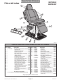
Pictorial Index .............................................. 6-2
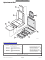
Upholstery Set ............................................. 6-3
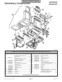
Upholstery Components ............................. 6-4.*
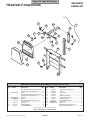
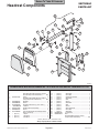
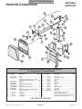
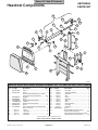
Headrest Components ................................ 6-5.*
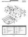
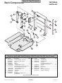
Back Components ...................................... 6-6.*
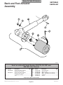
Back and Foot Actuator Assembly ............. 6-7.*
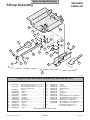
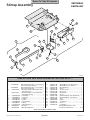
Seat Components ...................................... 6-8.*
Stirrup Assembly ....................................... 6-9.*
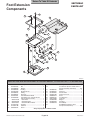
Foot Extension Components .................... 6-10.*
Footboard Components .............................. 6-11
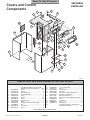
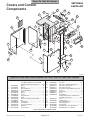
Covers and Control Components .............. 6-12.*
Inner Member Components ........................ 6-13
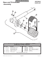
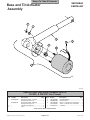
Base and Tilt Actuator Assembly ............. 6-14.*
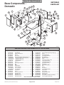
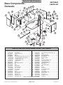
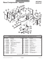
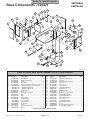
(*) Indicates that there has been a serial number break for the illustration
and that there are additional point page(s) following the original page.
© Midmark Corporation 1995 SF-1492 Rev. 9/00
Page i
Printed in U.S.A.
Return To Table Of Contents
TABLE OF CONTENTS - CONTINUED
Section/Paragraph
Page
Section/Paragraph
Page
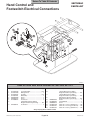
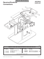
Receiver Electrical Connections ............... 6-21.*
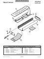
Hand Control ........................................... 6-22.*
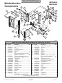
Middle Member Components .................... 6-15.*
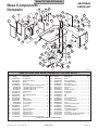
Base Components - Domestic .................. 6-16.*
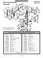
Base Components - Export ...................... 6-17.*
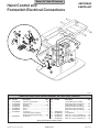
Hand Control and Footswitch Electrical
Connections .......................................... 6-18.*
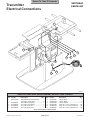
Transmitter Electrical Connections ........... 6-19.*
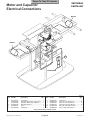
Motor and Capacitor Electrical
Connections ............................................ 6-20
COMMENTS ............................................................ 7-1
FAX ORDERING FORM .......................................... 7-2
(*) Indicates that there has been a serial number break for the illustration
and that there are additional point page(s) following the original page.
© Midmark Corporation 1995 SF-1492 Rev. 5/99
Page ii
Printed in U.S.A.
Return To Table Of Contents
IMPORTANT INSTRUCTIONS
General Safety Instructions
NOTE
Safety First: The primary concern of Midmark
Corporation is that this table is maintained with the
safety of the patient and staff in mind. To assure that
services and repairs are completed safely and correctly,
proceed as follows:
(1) Read this entire manual before performing any
services or repairs on this table.
(2) Be sure you understand the instructions
contained in this manual before attempting to
service or repair this table.
Safety Alert Symbols
Throughout this manual are safety alert symbols that
call attention to particular procedures. These items are
used as follows:
DANGER
A DANGER is used for an imminently
hazardous operating procedure,
practice, or condition which, if not correctly
followed, will result in loss of life or serious
personal injury.
A NOTE is used to amplify an operating procedure,
practice or condition.
Warranty Instructions
Refer to the Midmark “Limited Warranty” printed in the
Installation and Operation Manual for warranty information. Failure to follow the guidelines listed below will
void the warranty and/or render the 411 Power Examination Table unsafe for operation.
• In the event of a malfunction, do not attempt to
operate the table until necessary repairs have been
made.
• Do not attempt to disassemble table, replace malfunctioning or damaged components, or perform
adjustments unless you are one of Midmark’s
authorized service technicians.
• Do not substitute parts of another manufacturer
when replacing inoperative or damaged components.
Use only Midmark replacement parts.
WARNING
A WARNING is used for a potentially
hazardous operating procedure,
practice, or condition which, if not correctly
followed, could result in loss of life or serious
personal injury.
CAUTION
A CAUTION is used for a potentially
hazardous operating procedure, practice,
or condition which, if not correctly followed, could
result in minor or moderate injury. It may also be
used to alert against unsafe practices.
EQUIPMENT ALERT
An EQUIPMENT ALERT is used for an
imminently or potentially hazardous
operating procedure, practice, or condition which, if
not correctly followed, will or could result in serious,
moderate, or minor damage to unit.
© Midmark Corporation 1995 SF-1492
Page iii
Printed in U.S.A.
Return To Table Of Contents
© Midmark Corporation 1995 SF-1492
Printed in U.S.A.
Return To Table Of Contents
SECTION I
GENERAL INFORMATION
SECTION I
GENERAL INFORMATION
1.1 Scope of Manual
This manual contains detailed troubleshooting, scheduled maintenance, maintenance, and service instructions for 411 Power Examination Table. This manual is
intended to be used by Midmark’s authorized service
technicians.
1.2 How to Use Manual
A. Manual Use When Performing Scheduled Maintenance.
B. Theory of Operation (See Figures 5-1 and 5-2
for wiring diagrams / electrical schematics)
(1) Perform inspections and services listed in
Scheduled Maintenance Chart (Refer to
para 3.1).
Electrical Power:
(2) If a component is discovered to be faulty or out
of adjustment, replace or adjust component in
accordance with maintenance/service instructions (Refer to para 4.1).
B. Manual Use When Table Is Malfunctioning And
Cause Is Unknown.
Line voltage (115 VAC for domestic units and 230 VAC
for export units) is supplied directly to the table's
interface board. There is a transformer and associated
follow-on circuitry on the interface board which reduces
the line voltage to 12 - 14 VDC. The 12-14 VDC
provides power to operate the circuitry of the PC logic
board, hand control, and foot control.
On domestic units, 115 VAC is continuously supplied to
the electrical receptacle. Export units do not have an
electrical receptacle.
(1) Perform an operational test on table (Refer to
para 2.1).
(2) Perform troubleshooting procedures listed in
Troubleshooting Guide (Refer to para 2.2).
Manual Operation of Base, Tilt, Back, and Foot Actuator
Assemblies:
(3) If a component is discovered to be faulty or out
of adjustment, replace or adjust component in
accordance with maintenance/service instructions (Refer to para 4.1).
C. Manual Use When Damaged Component Is Known.
(1) Replace or adjust component in accordance
with maintenance/service instructions (Refer to
para 4.1).
1.3 Description Of 411 Power Examination Table
The major serviceable components of the table are the
headlock, back actuator, back transmitter, back receiver, back capacitor, foot actuator, foot transmitter,
foot receiver, foot capacitor, tilt actuator, tilt transmitter,
tilt receiver, tilt capacitor, base actuator, base transmitter, base receiver, base capacitor, base down limit
switch, chain assembly, base slide assembly, gas
spring(s), program panel, program panel interface
board, PC logic board, interface board, hand control
panel, hand control PC board, foot control foot
switches, and pan safety limit switch.
When a manual function is selected using the manual
positioning buttons on the hand control or program
panel, a signal is sent thru the PC logic board to the
interface board. The signal causes the appropriate
relay on the interface board to energize (i.e., if the TILT
UP button is depressed on hand control, the Tilt UP
relay on interface board is energized). Line voltage is
continuously supplied to all relays on interface board.
So, when a relay is energized, the line voltage flows
thru the relay and is applied across the windings of the
actuator motor, causing it to run. When the hand
control button is released, the relay de-energizes,
removing the line voltage from the windings of the
actuator motor and causing it to stop running.
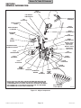
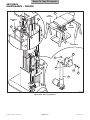
A. General Description (See Figure 1-1).
The 411 Power Examination Table is an examination
table designed specifically for performing general
medical examinations and procedures.
© Midmark Corporation 1995 SF-1492
Page 1-1
Printed in U.S.A.
Return To Table Of Contents
SECTION I
GENERAL INFORMATION
BACK
ACTUATOR
PAN SAFETY
LIMIT SWITCH
HEADLOCK
ASSEMBLY
TILT
ACTUATOR
HAND CONTROL
PANEL
BACK
RECEIVER
HAND CONTROL
PC BOARD
BACK
TRANSMITTER
PROGRAM
PANEL
TILT
TRANSMITTER
PC
LOGIC
BOARD
BASE
TRANSMITTER
BACK or FOOT
CAPACITOR
(SEE NOTE)
PROGRAM PANEL
INTERFACE BOARD
BACK or FOOT
CAPACITOR
(SEE NOTE)
FOOT
TRANSMITTER
TILT
CAPACITOR
CHAIN
ASSEMBLY
FOOT
RECEIVER
BASE
CAPACITOR
FOOT
ACTUATOR
BASE
SLIDE
ASSEMBLY
BASE
RECEIVER
TILT
RECEIVER
INTERFACE
BOARD
GAS
SPRING(S)
BASE
DOWN
LIMIT
SWITCH
NOTE: THE FOOT AND BACK CAPACITORS MAY BE SWITCHED ON
SOME UNITS. CHECK THE WIRE COLORS OF THESE CAPACITORS
TO DETERMINE FOOT OR BACK CAPACITOR LOCATION. RED WIRES
ARE CONNECTED TO THE BACK CAPACITOR AND YELLOW WIRES
ARE CONNECTED TO THE FOOT CAPACITOR.
BASE
ACTUATOR
FOOT CONTROL
FOOT SWITCH
MA301800
Figure 1-1. Major Components
© Midmark Corporation 1995 SF-1492 Rev. 4/97
Page 1-2
Printed in U.S.A.
Return To Table Of Contents
SECTION I
GENERAL INFORMATION
Actuator Operation:
The Base, Tilt, Back, and Foot actuators are ball screw
driven. The actuator assemblies contain a pivot point
on the end of the ball screw. If an actuator assembly is
run to the end of its stroke, the ball screw shaft spins
inside the nut, which allows the actuator assembly to
run without damaging or advancing the nut.
The Base, Tilt, Back, and Foot actuators have internal
braking mechanisms which use a friction device to keep
actuator stationary when the actuator is not being run.
Programming Operation:
The model 411 can be programmed for up to eight
operator specified positions. To program a position into
memory, the operator uses the manual positioning
buttons on the hand control or program panel to position the table top in the desired position. Now, the PC
logic board determines the position of each function as
follows: each actuator has a transmitter and a receiver
attached to it; the receiver is mounted to the motor end
of the actuator and is stationary while the transmitter is
mounted to the moving actuator shaft of the actuator.
The PC logic board has the transmitter on each actuator shaft continuously transmit a high frequency sound
wave which is received by its receiver. The PC logic
board compares the transmit point on the wave form
against the receive point on the wave form and uses
this data to determine the distance between the transmitter and receiver for each actuator. The PC logic
board uses this frequency measuring technique to
determine the position of the actuators at all times. The
operator now presses the PROGRAM button followed
by one of the eight PROGRAMMED POSITION buttons. The red L.E.D. under the PROGRAM button will
illuminate when the PROGRAM button is pressed and
will remain illuminated for four seconds to inform the
operator that he / she may now select a PROGRAMMED POSITION button (1 thru 8). After four
seconds, the PROGRAM function will automatically
disable itself if a PROGRAMMED POSITION button
has not been selected. When a PROGRAMMED
POSITION button is pressed, the receive point on the
wave form for each actuator is stored into memory.
Now the operator can easily return to the position
stored in memory. To do so, the operator presses and
holds the PROGRAMMED POSITION button (1 thru 8)
which has the desired position stored in memory. The
PC logic board compares the receive point on the wave
© Midmark Corporation 1995 SF-1492 Rev. 9/97
form that is actually being measured by each actuator's
transmitter / receiver set, against the value stored in the
PC logic board's memory. The PC logic board then
energizes the appropriate relays and allows each
actuator to run until the receive point on the wave form
being measured by each actuator's transmitter / receiver set is equal to the value stored in the PC logic
board's memory. When the values are equal, the relays
are de-energized, stopping the actuators.
Auto Return Operation:
When the operator presses the AUTO RETURN button,
the PC logic board energizes the base actuator's down
relay, causing the base actuator to run. The base
actuator lowers until the base down limit switch is
tripped. The PC logic board also senses that the base
down limit switch is tripped and de-energizes the base
actuator relays.
If the operator, at any time, wishes to stop the auto
return function, he / she can press the STOP button.
The PC logic board senses that the STOP button has
been pressed and de-energizes the base actuator
relays, causing the base actuator to stop.
Pan Safety Limit Switch:
The table has a N.O. pan safety limit switch. If the pan
assembly is not pushed into its fully stowed position, the
pan safety limit switch will not be tripped and there will
be an open circuit. If the pan safety limit switch circuit
is open, no power can reach the foot actuator windings,
preventing movement of the FOOT UP and FOOT
DOWN function. This safety feature prevents the
operator from accidentally colliding the foot section into
the treatment pan assembly.
General Information:
All actuator motors have a thermal overload switch
which will activate if the actuator assembly is run
continuously. The actuator motor was not designed for
continuous operation. The normal cool off period for
the thermal overload switches is 10 - 20 minutes.
Each actuator motor has a capacitor which provides
start up power and motor run power.
There is a 0.15 amp fuse, located on the interface
board, which provides over-current protection for the
transformer.
Page 1-3
Printed in U.S.A.
Return To Table Of Contents
SECTION I
GENERAL INFORMATION
There are four 5 amp slow blow fuses, located on the
interface board, which provide over-current protection
for each function's motors (i.e, Tilt fuse protects tilt
actuator motor).
Weight Capacity (Maximum) ............. 300 lb. (136.0 kg)
Under the control console, there is an ON / OFF switch.
Turning the switch to OFF disables movement of the
table, preventing accidental table movement or patients
from operating table. A red CONTROL PANEL
POWER L.E.D. illuminates when the ON / OFF switch
is in the ON position.
1.4 Specifications
Power Consumption:
115 VAC Unit ......................................... 1440 WATTS,
12 amps @ 120 VAC
230 VAC Unit ........................................ 2400 WATTS,
10 amps @ 240 VAC
Recommended Circuit:
A separate (dedicated) circuit is recommended for
this table. The table should not be connected to an
electrical circuit with other appliances or equipment
unless the circuit is rated for the additional load.
Factual data for the 411 Power Examination Table is
provided in Table 1-1. Also, see Figure 1-2.
Table 1-1. Specifications
Description
Electrical Requirements:
115 VAC Unit ........................... 110 - 120 VAC, 60 HZ,
12 amp, single phase
230 VAC Unit ...................... 220 - 240 VAC, 50/60 HZ,
10 amp, single phase
Data
1.5 Parts Replacement Ordering
Weight:
Without Shipping Carton ................ 550 lb (249.5 kg)
With Shipping Carton ..................... 625 lb (283.5 kg)
If a part replacement is required, order the part directly
from the factory as follows:
Shipping Carton ....... 58 in. "L" x 42 in. "W" x 31 in. "H"
(147.3 cm x 106.7 cm x 78.7 cm)
Dimensions (See Figure 1-2):
Table Top Length ......................... 70.5 in. (179.0 cm)
Table Top Length (headrest extended) .............. 81 in.
(205.7 cm)
Table Top Width ................................ 27 in. (68.6 cm)
Overall Width ..................................... 27 in. (68.6 cm)
Table Adjustment:
Back Section ................................................... 0 to 85°
Foot Section ................................................... 0 to -87°
Tilt Function ..................................................... 0 to 42°
Table Top Height (Adjustable): ...................25.75 in. to
41.625 in.
(65.4 cm to 105.7 cm)
Table Speeds:
TABLE UP ......................................... 12 +/- 1 seconds
BACK UP .......................................... 10 +/- 1 seconds
TILT UP ............................................. 11 +/- 1 seconds
FOOT UP .......................................... 10 +/- 1 seconds
© Midmark Corporation 1995 SF-1492
Page 1-4
(1) Refer to Figure 1-3 to determine the location of
the model number and serial number of the
table and record this data.
(2) Refer to the Parts List to determine the item
numbers of the parts, part numbers of the
parts, descriptions of the parts, and quantities
of parts needed and record this data (Refer to
para 6.1).
NOTE
Ask the Purchasing Department of the company that
owns the table for this information. Otherwise, this
information may be obtained from the dealer that
sold the table.
(3) Determine the installation date of the table and
record this data.
(4) Call Midmark with the recorded information and
ask for the Medical Products Technical Services Department. See back cover of this
manual for the phone number or use the Fax
Order Form (See page 7-2 for Fax Order
Form).
Printed in U.S.A.
Return To Table Of Contents
SECTION I
GENERAL INFORMATION
81"
70 1/2"
23 1/2"
(BASE)
27"
(TABLE TOP)
87°
(MAX.)
85°
(MAX.)
42°
(MAX.)
POWER
CORD
(78")
41 5/8"
(MAX.)
25 3/4"
(MIN.)
10 1/2"
33"
MA301900
Figure 1-2. Table Dimensions
1.6 Special Tools
Table 1-2 lists all of the special tools needed to repair
the table, how to obtain the special tools, and the
purpose of each special tool.
Table 1-2. Special Tool List
Description of Special Tool
Manufacturer's
Name / Address / Phone
Manufacturer's
Part Number
Purpose of Special Tool
Multimeter
Commercially Available
Any Type
Used to perform continuity and voltage checks.
Torque Wrench
Commercially Available
Any Type
Used to tighten nuts or screws to specified values.
Support Bar
Midmark Corporation
60 Vista Drive
Versailles, Ohio 45380
(513) 526-3662
051-0412-00
Used to support the weight of the table top so the
base actuator may be disconnected from table.
Used in base actuator removal and gas spring(s)
removal procedures.
Pry Bar
Midmark Corporation
60 Vista Drive
Versailles, Ohio 45380
(513) 526-3662
051-0413-00
Used to compress the gas spring(s) so they may
be disconnected and removed from table.
© Midmark Corporation 1995 SF-1492
Page 1-5
Printed in U.S.A.
Return To Table Of Contents
SECTION I
GENERAL INFORMATION
MODEL
NUMBER
RK
MA
MID
X
-00
411 VACZ
X
XX /XX HXX
X X
P X XX
O.
AM AVX
L N T XX
DE INPU G
O
M
TIN .
RA L NO
RIA
SE
SERIAL
NUMBER
MA302000
Figure 1-3. Model Number / Serial Number Location
© Midmark Corporation 1995 SF-1492
Page 1-6
Printed in U.S.A.
Return To Table Of Contents
SECTION II
TESTING AND TROUBLESHOOTING
SECTION II
TESTING AND TROUBLESHOOTING
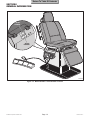
2.1 Operational Test (See Figure 2-1)
Table Speeds:
TABLE UP ......................................... 12 +/- 1 seconds
BACK UP .......................................... 10 +/- 1 seconds
TILT UP ............................................. 11 +/- 1 seconds
FOOT UP .......................................... 10 +/- 1 seconds
In order to effectively diagnose the malfunction of the
table, it may be necessary to perform an operational
test as follows:
(4) Repeat steps 2 and 3 on the table's console. If
the table has a foot control, repeats steps 2 and
3 for the foot control also.
WARNING
Refer to the Operator Manual for
complete instructions on operating the
table. Failure to do so could result in personal
injury.
(5) Lower FOOT DOWN function almost all the
way down. Pull the pan slide assembly outward until the pan safety limit switch is no
longer tripped. Press FOOT UP and then
FOOT DOWN button on hand control.
NOTE
The Operational Test, for the most part, only describes what should happen when the table is
operated. If the table does something other than
described, a problem has been discovered. Refer to
the Troubleshooting Guide to determine the cause of
the problem and its correction.
(6) Observe. The foot section of table top should
not move when FOOT UP or FOOT DOWN
buttons are pressed.
(7) Push pan slide assembly inward until pan
safety limit switch is tripped. Press FOOT UP
and then FOOT DOWN button on hand control.
(1) Plug the table into a grounded, non-isolated,
correctly polarized outlet, that has the proper
voltage output for the table. See Figure 2-1.
(8) Observe. The foot section of table top should
move when FOOT UP or FOOT DOWN buttons
are pressed.
NOTE
The pan slide assembly should be pushed in fully for
the following step.
(2) Press TABLE UP, TABLE DOWN, BACK UP,
BACK DOWN, TILT UP, TILT DOWN, FOOT
UP, and FOOT DOWN buttons on hand control.
(3) Observe. The table top should move in the
direction corresponding to the button which is
being depressed. No section of the table top
should drift on its own after hand control button
is released. No actuator assembly should
make excessive squealing noises. Movement
should be steady and should match the positions and speeds listed below:
Table Positions:
Back Section ................................................... 0 to 85°
Foot Section ................................................... 0 to -87°
Tilt Function ..................................................... 0 to 42°
Table Top Height (Adjustable): ................... 25.75 in. to
41.625 in.
(65.4 cm to 105.7 cm)
© Midmark Corporation 1995 SF-1492
Page 2-1
NOTE
Once the PROGRAM button is pressed, the operator
has four seconds to press one of the eight PROGRAMMED POSITION buttons.
(9) Press the PROGRAM button followed by the
PROGRAMMED POSITION button labeled "1".
(10) Observe. When the PROGRAM button is
pressed, the red L.E.D. directly above it should
illuminate.
(11) Use the manual positioning buttons to move the
table top to a new position.
NOTE
Steps 12 thru 14 check functionality of PROGRAMMED POSITION buttons 1 thru 8 on console.
(12) Press and hold the PROGRAMMED POSITION
button "1" (located on console) until the table
top stops moving.
Printed in U.S.A.
Return To Table Of Contents
SECTION II
TESTING AND TROUBLESHOOTING
PROGRAMMED
POSITION
BUTTONS
BACK
SECTION
POINT
"A"
PROGRAM
L.E.D.
1 2
3 4
5 6
7 8
AXIS
"C"
AXIS
"B"
LOWER
LOCK
HANDLE
AUTO RETURN
"STOP" BUTTON
AUTO RETURN
"START" BUTTON
CONTROL PANEL
POWER "ON / OFF"
SWITCH
MANUAL
POSITION
BUTTONS
CONTROL
PANEL
POWER
L.E.D.
UPPER
LOCK
HANDLE
PROGRAM
BUTTON
VIEW
ROTATED 90°
MANUAL
POSITION
BUTTONS
HEADREST
SECTION
PROGRAMMED
POSITION
BUTTONS
TABLE
TOP
BACK
SECTION
SEAT
SECTION
FOOT
SECTION
HAND
CONTROL
HAND
CONTROL
TABLE
DOWN
TABLE
UP
TILT
UP
TILT
DOWN
PAN SLIDE
ASSEMBLY
BACK
UP
BACK
DOWN
FOOT
UP
FOOT
DOWN
CONSOLE
MA302100
Figure 2-1. Operational Test
© Midmark Corporation 1995 SF-1492
Page 2-2
Printed in U.S.A.
Return To Table Of Contents
SECTION II
TESTING AND TROUBLESHOOTING
(13) Observe. The table top should move back to
the position that was stored into memory of "1"
in step 9.
(23) Switch the CONTROL PANEL POWER switch
to OFF.
(24) Observe. The CONTROL PANEL POWER
L.E.D. should extinguish when the switch is
switched to OFF.
(14) Repeat steps 9 thru 13 to test the PROGRAMMED POSITION buttons "2 thru 8" on
the console.
(25) Press one of the MANUAL POSITION buttons
or PROGRAMMED POSITION buttons.
NOTE
Steps 15 thru 17 check functionality of PROGRAMMED POSITION buttons 1 thru 8 on hand
control.
(26) Observe. The table top should not move when
a MANUAL POSITION button or PROGRAMMED POSITION button is pressed.
(15) Press and hold the PROGRAMMED POSITION
button "1" (located on hand control) until the
table top stops moving.
NOTE
Early units have a headrest which has only one
locking handle. The procedure is the same otherwise.
(16) Observe. The table top should move back to
the position that was stored into memory of "1"
in step 9.
(27) Unlock upper lock handle and lower lock
handle, position headrest in a horizontal
position as shown, and then relock upper lock
handle and lower lock handle.
(17) Repeat steps 15 and 16 to test the PROGRAMMED POSITION buttons "2 thru 8" on
the hand control.
(28) Place a 45 lb (20.4 kg) static load at Point A.
(18) Press the TABLE UP button to run the table top
all the way up.
(29) Observe. There should be no movement at
Axis B or Axis C when the static load is applied
to the headrest. The maximum force required
to unclamp a locking handle should be 17 lbs.
(7.7 kg) and the maximum force required to
clamp a locking handle should be 35 lbs. (15.8
kg).
(19) Press the AUTO RETURN "START" button,
wait one second, and then press the AUTO
RETURN "STOP" button.
(20) The base actuator should begin to lower the
table top. When the STOP button is pressed,
the base actuator should stop lowering.
2.2 Troubleshooting Procedures
(21) Press the AUTO RETURN "START" button and
allow the table top to lower all the way down.
Table 2-1 is a Troubleshooting Guide which is used to
determine the cause of the malfunction.
(22) Observe. The base actuator should lower the
table top all the way down. The base actuator
should not continue to run after table top is
completely lowered.
© Midmark Corporation 1995 SF-1492
Page 2-3
Printed in U.S.A.
Return To Table Of Contents
SECTION II
TESTING AND TROUBLESHOOTING
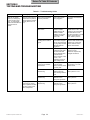
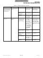
Table 2-1. Troubleshooting Guide
Problem
Table will not operate
when any of the eight up
or down functions, auto
return, or programmed
positions are selected from
the hand control or
console.
© Midmark Corporation 1995 SF-1492
Symptom
Probable Cause
When any hand control or Power cord is not plugged
console button is pressed, into facility wall outlet.
nothing happens (actuator
motor(s) does not run or
hum).
Check
Check to see if power
cord is plugged in.
Correction
Plug power cord into facility
wall outlet.
CONTROL PANEL POWER Check to see if
switch is OFF.
CONTROL PANEL
POWER switch is ON.
CONTROL PANEL
POWER L.E.D. should
illuminate to indicate
switch is ON.
Turn CONTROL PANEL
POWER switch to ON. Inform
operator on use of the switch.
If the table does not work
even when the switch is in ON
position, replace PC logic
board. Refer to para 4.6.
Facility circuit breaker
providing power to table is
tripped.
Check to see if facility
circuit breaker is tripped.
One way of checking this
is to plug a lamp into wall
outlet that table was
plugged into.
If circuit breaker is tripped,
determine what caused circuit
breaker to trip, correct the
problem, and then reset /
replace circuit breaker.
Wire connections loose.
Check all wiring
connections from power
cord to terminal block
and from terminal block
to interface board.
Perform continuity check
on wires. Use
multimeter to check for
proper voltage levels.
Clean any dirty connections.
Tighten any loose
connections. Replace any
damaged connections.
0.15 amp transformer
primary fuse on interface
board is blown.
Refer to Figure 5-1 or
5-2 for this check.
Perform continuity check
on primary fuse.
Replace blown primary fuse.
See Figure 5-1 or 5-2 for
location of fuse.
Interface board is
malfunctioning.
Replace suspect
interface board with
known working interface
board.
Replace interface board.
Refer to para 4.4 or 4.5.
PC logic board is
malfunctioning.
Replace suspect PC logic Replace PC logic board.
board with known
Refer to para 4.6.
working PC logic board.
Nothing happens when a
PC logic board is
hand control or console
malfunctioning.
button is pressed, but table
runs when a foot control
switch is depressed.
Replace suspect PC logic Replace PC logic board.
board with known
Refer to para 4.6.
working PC logic board.
Page 2-4
Printed in U.S.A.
Return To Table Of Contents
SECTION II
TESTING AND TROUBLESHOOTING
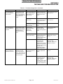
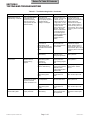
Table 2-1. Troubleshooting Guide - Continued
Problem
One or more functions
cannot be initiated from
the hand control.
One or more functions
cannot be initiated from
the console.
One or more functions
cannot be initiated from
the optional foot control.
© Midmark Corporation 1995 SF-1492
Symptom
Probable Cause
Some functions may be
initiated from the hand
control, but at least one
may not. All functions can
be initiated from the
console.
Hand control panel of hand
control is malfunctioning
(switch membrane is
malfunctioning).
Replace suspect hand
Replace hand control panel.
control panel with known Refer to para 4.8.
working hand control
panel.
Hand control board is
malfunctioning.
Replace suspect hand
Replace hand control board.
control board with known Refer to para 4.8.
working hand control
board.
Hand control coil cord has
bad connection or there is a
break in coil cord.
Replace suspect coil cord Replace coil cord.
with known working coil
cord.
Program panel is
malfunctioning (switch
membrane is
malfunctioning).
Replace suspect
program panel with
known working program
panel.
Replace program panel.
Refer to para 4.7.
Program panel interface
board is malfunctioning.
Replace suspect
program panel interface
board with known
working program panel
interface board.
Replace program panel
interface board. Refer to
para 4.7.
Wire connections loose.
Check all wiring
connections from
program panel to
program panel interface
board to PC logic board.
Perform continuity check
on wires. Use
multimeter to check for
proper voltage levels.
Clean any dirty connections.
Tighten any loose
connections. Replace any
damaged connections.
Foot switch for
non-operable function is
malfunctioning.
Perform a continuity
check on suspect foot
switch.
Replace foot switch. Refer to
para 4.27.
Wire connections loose.
Check all wiring
connections from foot
control to interface
board. Perform
continuity check on wires.
Use multimeter to check
for proper voltage levels.
Clean any dirty connections.
Tighten any loose
connections. Replace any
damaged connections.
Some functions may be
initiated from the console,
but at least one may not.
All functions can be
initiated from the hand
control.
Some functions may be
initiated from the foot
control, but at least one
may not. All functions can
be initiated from the hand
control and console.
Page 2-5
Check
Correction
Printed in U.S.A.
Return To Table Of Contents
SECTION II
TESTING AND TROUBLESHOOTING
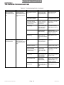
Table 2-1. Troubleshooting Guide - Continued
Problem
BACK UP and BACK
DOWN functions do not
work. All other functions
work.
Symptom
When BACK UP and
BACK DOWN buttons are
pressed, the table will not
move (all other functions
work).
Probable Cause
BACK capacitor is weak or
blown.
Thermal overload switch in
back actuator is activated.
TILT UP and TILT DOWN
functions do not work. All
other functions work.
When TILT UP and TILT
DOWN buttons are
pressed, the table will not
move (all other functions
work).
Replace suspect back
capacitor with known
working back capacitor.
-
Correction
Replace back capacitor.
Refer to para 4.10.
Wait 10 to 20 minutes to allow
back actuator motor to cool.
5 amp BACK fuse for BACK
UP and BACK DOWN
functions is blown (located
on interface board).
Refer to Figure 2-2 for
this check. Perform a
continuity check on 5
amp BACK fuse.
Replace blown BACK fuse.
See Figure 5-1 or 5-2 for
location of fuse.
Back actuator assembly is
malfunctioning.
Replace suspect back
actuator assembly with
known working back
actuator assembly.
Replace actuator motor or
back actuator assembly.
Refer to para 4.21 or 4.12.
Wire connections loose.
Check all wiring
connections to back
actuator assembly.
Clean any dirty connections.
Tighten any loose
connections. Replace any
damaged connections.
Interface board is
malfunctioning
Replace suspect
interface board with
known working interface
board.
Replace interface board.
Refer to para 4.4 or 4.5.
Tilt capacitor is weak or
blown.
Replace suspect tilt
capacitor with known
working tilt capacitor.
Replace tilt capacitor. Refer
to para 4.10.
Thermal overload switch in
tilt actuator is activated.
© Midmark Corporation 1995 SF-1492
Check
-
Wait 10 to 20 minutes to allow
tilt actuator motor to cool.
5 amp TILT fuse for TILT
UP and TILT DOWN
functions is blown (located
on interface board).
Refer to Figure 5-1 or
5-2 for this check.
Perform a continuity
check on 5 amp TILT
fuse.
Replace blown TILT fuse.
See Figure 5-1 or 5-2 for
location of fuse.
Tilt actuator assembly is
malfunctioning.
Replace suspect tilt
actuator assembly with
known working tilt
actuator assembly.
Replace actuator motor or tilt
actuator assembly. Refer to
para 4.21 or 4.16.
Wire connections loose.
Check all wiring
connections to tilt
actuator assembly.
Clean any dirty connections.
Tighten any loose
connections. Replace any
damaged connections.
Interface board is
malfunctioning
Replace suspect
interface board with
known working interface
board.
Replace interface board.
Refer to para 4.4 or 4.5.
Page 2-6
Printed in U.S.A.
Return To Table Of Contents
SECTION II
TESTING AND TROUBLESHOOTING
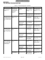
Table 2-1. Troubleshooting Guide - Continued
Problem
TABLE UP and TABLE
DOWN functions do not
work. All other functions
work.
Symptom
Probable Cause
When TABLE UP and
Base capacitor is weak or
TABLE DOWN buttons are blown.
pressed, the table will not
move (all other functions
work).
Thermal overload switch in
base actuator is activated.
FOOT UP and FOOT
DOWN functions do not
work. All other functions
work.
When FOOT UP and
FOOT DOWN buttons are
pressed, the table will not
move (all other functions
work).
Replace suspect base
capacitor with known
working base capacitor.
-
Correction
Replace base capacitor.
Refer to para 4.10.
Wait 10 to 20 minutes to allow
base actuator motor to cool.
5 amp TABLE fuse for
TABLE UP and TABLE
DOWN functions is blown
(located on interface board).
Refer to Figure 2-2 for
this check. Perform a
continuity check on 5
amp TABLE fuse.
Replace blown TABLE fuse.
See Figure 5-1 or 5-2 for
location of fuse.
Base actuator assembly is
malfunctioning.
Replace suspect base
actuator assembly with
known working base
actuator assembly.
Replace actuator motor or
base actuator assembly.
Refer to para 4.21 or 4.18.
Wire connections loose.
Check all wiring
connections to base
actuator assembly.
Clean any dirty connections.
Tighten any loose
connections. Replace any
damaged connections.
Interface board is
malfunctioning
Replace suspect
interface board with
known working interface
board.
Replace interface board.
Refer to para 4.4 or 4.5.
Pan holder assembly is not
Check that pan holder
pushed in all the way;
assembly is pushed in all
therefore the pan safety limit the way.
switch is not tripped.
Push pan holder assembly in
all the way. Inform operator
on how the pan safety limit
switch works.
Foot capacitor is weak or
blown.
Replace foot capacitor. Refer
to para 4.10.
Thermal overload switch in
foot actuator is activated.
© Midmark Corporation 1995 SF-1492
Check
Replace suspect foot
capacitor with known
working foot capacitor.
-
Wait 10 to 20 minutes to allow
foot actuator motor to cool.
5 amp FOOT fuse for FOOT
UP and FOOT DOWN
functions is blown (located
on interface board).
Refer to Figure 2-2 for
this check. Perform a
continuity check on 5
amp FOOT fuse.
Replace blown FOOT fuse.
See Figure 5-1 or 5-2 for
location of fuse.
Foot actuator assembly is
malfunctioning.
Replace suspect foot
actuator assembly with
known working foot
actuator assembly.
Replace actuator motor or
foot actuator assembly. Refer
to para 4.21 or 4.14.
Wire connections loose.
Check all wiring
connections to base
actuator assembly.
Clean any dirty connections.
Tighten any loose
connections. Replace any
damaged connections.
Interface board is
malfunctioning
Replace suspect
interface board with
known working interface
board.
Replace interface board.
Refer to para 4.4 or 4.5.
Page 2-7
Printed in U.S.A.
Return To Table Of Contents
SECTION II
TESTING AND TROUBLESHOOTING
Table 2-1. Troubleshooting Guide - Continued
Problem
FOOT UP and FOOT DOWN
functions do not work. All
other functions work Continued.
Symptom
When FOOT UP and
Pan safety switch is out of
FOOT DOWN buttons
adjustment.
are pressed, the table will
not move (all other
functions work) Continued.
BACK UP function works, but One function operates
BACK DOWN function does properly, but the other
not or BACK DOWN function does not.
works, but BACK UP function
does not. All other functions
work.
TILT UP function works, but
TILT DOWN function does
not or TILT DOWN function
works, but TILT UP function
does not. All other functions
work.
TABLE UP function works,
but TABLE DOWN function
does not or TABLE DOWN
function works, but TABLE
UP function does not. All
other functions work.
One function operates
properly, but the other
does not.
One function operates
properly, but the other
does not.
TABLE UP does not
work, but TABLE DOWN
does
© Midmark Corporation 1995 SF-1492
Probable Cause
Check
Check to see if pan
safety limit switch is being
tripped by pan holder
assembly.
Correction
Adjust pan safety limit switch
so it is tripped when pan
holder assembly is pushed in
all the way.
Pan safety limit switch is
malfunctioning.
Perform continuity check Replace pan safety limit
on pan safety limit switch switch. Refer to para 4.9.
(switch tripped = closed).
Wire connections loose.
Check all wiring
connections to back
actuator assembly.
Clean any dirty connections.
Tighten any loose
connections. Replace any
damaged connections.
Interface board is
malfunctioning (relay for up
or down function is
malfunctioning).
Replace suspect
interface board with
known working interface
board.
Replace interface board.
Refer to para 4.4 or 4.5.
Back actuator assembly is
malfunctioning.
Replace suspect back
actuator assembly with
known working back
actuator assembly.
Replace actuator motor or
back actuator assembly.
Refer to para 4.21 or 4.12.
Wire connections loose.
Check all wiring
connections to tilt
actuator assembly.
Clean any dirty connections.
Tighten any loose
connections. Replace any
damaged connections.
Interface board is
malfunctioning (relay for up
or down function is
malfunctioning).
Replace suspect
interface board with
known working interface
board.
Replace interface board.
Refer to para 4.4 or 4.5.
Tilt actuator assembly is
malfunctioning.
Replace suspect tilt
actuator assembly with
known working tilt
actuator assembly.
Replace actuator motor or tilt
actuator assembly. Refer to
para 4.21 or 4.16.
Wire connections loose.
Check all wiring
connections to base
actuator.
Clean any dirty connections.
Tighten any loose
connections. Replace any
damaged connections.
Interface board is
malfunctioning (relay for up
or down function is
malfunctioning).
Replace suspect
interface board with
known working interface
board.
Replace interface board.
Refer to para 4.4 or 4.5.
Base actuator assembly is
malfunctioning.
Replace suspect base
actuator assembly with
known working base
actuator assembly.
Replace actuator motor or
base actuator assembly.
Refer to para 4.21 or 4.18.
Gas spring(s) are weak.
Replace suspect gas
spring(s) with known
working gas spring(s)
Replace gas spring(s). Refer
to para 4.19.
Page 2-8
Printed in U.S.A.
Return To Table Of Contents
SECTION II
TESTING AND TROUBLESHOOTING
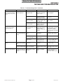
Table 2-1. Troubleshooting Guide - Continued
Problem
FOOT UP function works,
but FOOT DOWN function
does not or FOOT DOWN
function works, but FOOT
UP function does not. All
other functions work.
Programming function is
malfunctioning.
© Midmark Corporation 1995 SF-1492
Symptom
One function operates
properly, but the other
does not.
Probable
Cause
Wire connections loose.
Check
Check all wiring
connections to foot
actuator assembly.
Correction
Clean any dirty connections.
Tighten any loose
connections. Replace any
damaged connections.
Interface board is
Replace suspect
malfunctioning (relay for up interface board with
or down function is
known working interface
malfunctioning).
board.
Replace interface board.
Refer to para 4.4 or 4.5.
Foot actuator assembly is
malfunctioning.
Replace suspect foot
actuator assembly with
known working foot
actuator assembly.
Replace actuator motor or
foot actuator assembly. Refer
to para 4.21 or 4.14.
Refer to Figure 5-1or
5-2 for this check. Check
L.E.D. (D1-Base,
D2-Foot, D3-Back, and
D4-Tilt) on PC logic
board. If L.E.D. is
illuminated, transmitter or
receiver for that function
could be out of
alignment. Align the
receiver and transmitter
for a function and then
see if the table goes to
the proper position when
a PROGRAMMED
POSITION button is
pressed.
Align the receiver and
transmitter of a function. If
this does not correct problem,
replace receiver and
transmitter for the suspect
function. Refer to para 4.11
for back function, para 4.13
for foot function, para 4.15 for
tilt function, para 4.17 for base
function.
RF cables for receiver and
transmitter are shorted or
open.
Perform continuity check
on RF cables.
Replace any damaged RF
cables.
Program panel is
malfunctioning (switch
membrane is
malfunctioning).
Replace suspect
program panel with
known working program
panel.
Replace program panel.
Refer to para 4.7.
Program panel interface
board is malfunctioning.
Replace suspect
program panel interface
board with known
working program panel
interface board.
Replace program panel
interface board. Refer to
para 4.7.
PC logic board is
malfunctioning.
Replace suspect PC logic Replace PC logic board.
board with known
Refer to para 4.6.
working PC logic board.
A table position cannot be The receiver and
programmed into
transmitter for a function
memory.
are not properly aligned or
are malfunctioning,
resulting in a lost signal.
Page 2-9
Printed in U.S.A.
Return To Table Of Contents
SECTION II
TESTING AND TROUBLESHOOTING
Table 2-1. Troubleshooting Guide - Continued
Problem
Programming function is
malfunctioning - Continued.
AUTO RETURN function
does not work.
Symptom
Probable Cause
Check
Correction
When a PROGRAMMED
POSITION button is
pressed, the table top
does not move to the
proper position that was
stored in memory.
The receiver and
transmitter for a function
are not properly aligned or
are malfunctioning,
resulting in a lost signal.
Refer to Figure 2-1 for
this check. Check L.E.D.
(D1-Base, D2-Foot,
D3-Back, and D4-Tilt) on
PC logic board. If L.E.D.
is illuminated, transmitter
or receiver for that
function could be out of
alignment. Align the
receiver and transmitter
for a function and then
see if the table goes to
the proper position when
a PROGRAMMED
POSITION button is
pressed.
Align the receiver and
transmitter of a function. If
this does not correct problem,
replace receiver and
transmitter for the suspect
function. Refer to para 4.11
for back function, para 4.13
for foot function, para 4.15 for
tilt function, para 4.17 for base
function.
The receiver or transmitter
for a function is
malfunctioning, but its
L.E.D. indicator light is not
illuminated on the interface
board.
Replace suspect receiver
and transmitter with
known working receiver
and transmitter.
Replace receiver and
transmitter for suspect
function. Refer to para 4.11
for back function, para 4.13
for foot function, para 4.15 for
tilt function, para 4.17 for base
function.
PC logic board is
malfunctioning.
Replace suspect PC logic Replace PC logic board.
board with known
Refer to para 4.6.
working PC logic board.
Program panel is
malfunctioning (switch
membrane is
malfunctioning).
Replace suspect
program panel with
known working program
panel.
Replace program panel.
Refer to para 4.7.
Program panel interface
board is malfunctioning.
Replace suspect
program panel interface
board with known
working program panel
interface board.
Replace program panel
interface board. Refer to
para 4.7.
Base down limit switch is
malfunctioning (stuck
open).
Perform continuity check Replace base down limit
on base down limit
switch. Refer to para 4.20.
switch.
When AUTO RETURN
“START” button is
pressed, nothing
happens.
After base actuator has
Base down limit switch is
lowered table top all the
out of adjustment.
way down, the base
actuator continues to run.
The Base, Tilt, Back, or Foot Function operates
function drifts by itself.
properly otherwise.
© Midmark Corporation 1995 SF-1492
Check adjustment of
base down limit switch.
Adjust base down limit switch.
Refer to para 4.20.
Base down limit switch is
malfunctioning (stuck
closed).
Perform continuity check Replace base down limit
on base down limit
switch. Refer to para 4.20.
switch.
Motor actuator brake is
malfunctioning.
Replace suspect actuator Replace actuator brake
brake components with
components. Refer to para
new components.
4.21.
Page 2-10
Printed in U.S.A.
Return To Table Of Contents
SECTION II
TESTING AND TROUBLESHOOTING
Table 2-1. Troubleshooting Guide - Continued
Problem
Table moves fine for light
patient, but will not move or
moves slowly for very heavy
patient.
Symptom
Heavy patients cause
table to malfunction.
Probable Cause
Check
Correction
Low voltage is being
supplied to table.
Check voltage at wall
receptacle - should be
115 +/- 5 VAC.
Correct low voltage situation
at wall receptacle.
Gas spring(s) are weak.
Replace suspect gas
spring(s) with known
working gas spring(s).
Replace gas spring(s). Refer
to para 4.19.
Table overloaded with too
heavy of a patient.
Maximum weight
capacity of table is 300
lbs (136.0 kg).
Inform table operator of
weight limitation.
Capacitor for suspect
function is weak.
Replace suspect
capacitor with known
working capacitor.
Replace capacitor.
Whirling or squeaking noise
is heard when an actuator
assembly is being run.
Noisy actuator.
Foreign matter on ball
Check for foreign matter
screw threads and / or lack on ball screw threads.
of lubricant.
Check for lack of
lubricant on ball screw
threads.
Clean all foreign matter off of
ball screw threads. Coat ball
screw threads with STP
treatment oil or equivalent. If
actuator assembly is still noisy,
replace it.
Excessive sideways play of
table top.
Table is not stable and
can be moved from side
to side.
Chain assemblies are
loose.
Check tension of chain
assemblies.
Adjust tension of chain
assemblies. Refer to para
4.22.
Base slide assembly is
worn or deformed.
Check condition of base
slide assembly.
Replace base slide assembly.
Table base is not resting
firmly on floor.
Check to verify all four
leveling screws are
contacting the floor.
Adjust the leveling screws;
there is one located under
each corner of the base.
Headrest drifts downward Headrest is out of
while supporting patients adjustment.
head.
Check adjustment of
headrest.
Adjust headrest. Refer to
para 4.23 or 4.25.
Headrest locking handles Headrest handles handle
pop out of locked position. stops need adjusted.
Check adjustment of
headrest handles handle
stops.
Adjust headrest handles
handle stops. Refer to para
4.24 or 4.26.
Stirrups do not lock into
one of the three positions
properly.
Check for damaged
parts.
Replace stirrup index pin or
any other necessary
components. Refer to para
4.28.
Headrest is not operating
properly.
Stirrups are malfunctioning.
© Midmark Corporation 1995 SF-1492
Stirrup index pin needs
replaced.
Page 2-11
Printed in U.S.A.
Return To Table Of Contents
SECTION II
TESTING AND TROUBLESHOOTING
© Midmark Corporation 1995 SF-1492
Page 2-12
Printed in U.S.A.
Return To Table Of Contents
SECTION III
SCHEDULED MAINTENANCE
SECTION III
SCHEDULED MAINTENANCE
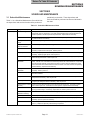
3.1 Scheduled Maintenance
Table 3-1 is a Scheduled Maintenance Chart which lists
the inspections and services that should be performed
periodically on the table. These inspections and
services should be performed as often as indicated in
the chart.
Table 3-1. Scheduled Maintenance Chart
Interval
Semi-annually
Inspection or Service
What to Do
Obvious damage
Visually check condition of table for obvious damage such as: cracks in components, missing
components, dents in components, or any other visible damage which would cause table to be
unsafe to operate or would compromise its performance. Repair table as necessary.
Fasteners / hardware
Check table for missing or loose fasteners / hardware. Replace any missing hardware and tighten
any loose hardware as necessary.
Warning and instructional Check for missing or illegible decals. Replace decals as necessary.
decals
Pivot points / moving
parts / accessories
Lubricate all exposed pivot points, moving parts, and accessories with silicone based lubricant.
Hand control
Check that hand control works correctly. Make sure all switch membranes work correctly. If
necessary, replace hand control panel. Refer to para 4.8.
Program panel
Check that program panel works correctly. Make sure all switch membranes work correctly. If
necessary, replace program panel. Refer to para 4.7.
Foot control (optional)
Check that foot control works correctly. Make sure all footswitches operate properly. Replace any
malfunctioning footswitches. Refer to para 4.27.
Ball screws of actuator
assemblies
Extend each actuator assembly and wipe ball screw threads down with a rag to remove foreign
matter. Coat as much of the ball screw threads as possible with STP treatment oil or equivalent.
Run each actuator assembly to both ends of its travel a couple of times to spread the oil evenly
over all of the ball screw threads and then remove excess oil. If oil does not correct a squealing
actuator assembly, replace actuator assembly.
Drifting of actuator
assemblies
Check each actuator assembly for drift. Replace actuator assembly brake components as
necessary. Refer to para 4.21.
Foot extension
Check that foot extension can be easily removed. Make sure foot section is latched securely in
place when installed.
Stirrup assemblies
Check that stirrup assemblies lock into one of three positions. Check for wear. Replace worn
components as necessary. Refer to para 4.28.
Pan safety limit switch
Check that pan safety limit switch is tripped when pan assembly is in fully stowed position. Adjust
or replace pan safety limit switch if necessary. Refer to para 4.9.
Excessive play in column
assembly
Check that column assembly does not have excessive side to side play. If necessary, tighten
chain. Refer to para 4.22. If this does not correct problem, replace base slide assembly.
Head rest
Check that head rest is adjusted properly and will not drift downward on its own under 45 lbs
(20.4 kg) of static weight. If necessary, adjust head rest. Refer to para 4.23 or 4.25
Electrical receptacle
(Domestic units only)
Check that the electrical receptacle is functioning properly. Replace receptacle as necessary.
Upholstery
Check all upholstery for rips, tears, or excessive wear. Replace cushions as necessary.
Accessories
Check that all accessories have all of their components and that they function properly. If
necessary, repair or replace the accessory.
Operational Test
Perform an Operational Test to determine if the table is operating within its specifications (Refer to
para 2.1). Replace or adjust any malfunctioning components.
© Midmark Corporation 1995 SF-1492
Page 3-1
Printed in U.S.A.
Return To Table Of Contents
SECTION III
SCHEDULED MAINTENANCE
© Midmark Corporation 1995 SF-1492
Page 3-2
Printed in U.S.A.
Return To Table Of Contents
SECTION IV
MAINTENANCE / SERVICE
SECTION IV
MAINTENANCE / SERVICE INSTRUCTIONS
4.1 Introduction
6
WARNING
3
Refer to the Operator Manual for
complete instructions on operating the
table. Failure to do so could result in personal
injury.
2
1
5
NOTE
Perform an operational test on the table after the
repair is completed to confirm the repair was properly
made and that all malfunctions were repaired.
ACCESS
HOLES
The following paragraphs contain removal, installation, repair, and adjustment procedures for the table.
4
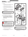
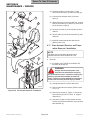
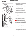
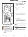
4.2 Shrouds Removal / Installation (Applies to Units With Serial Numbers
AV-1000 Thru AV2888)
9
8
10
8
A. Removal
(1) If possible, raise TILT UP function all the way
up.
WARNING
Always disconnect the power cord
from the wall outlet before removing
any of the table's covers / shrouds or making any
repairs to prevent the possibility of electrical
shock. Failure to comply with these instructions
could result in severe personal injury or death.
OPERATOR'S
CONSOLE
(2) Unplug table power cord from wall outlet.
7
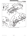
NOTE
Remove guide weldment (5) from side of table which
does not have operator's console. Also, early units
do not have access holes with plugs (1).
MA302200
Figure 4-1. Shrouds Removal / Installation
(3) Remove two plugs (1, Figure 4-1) from access
holes; then remove two screws (2),
lockwashers (3), two screws (4) and guide
weldment (5) from seat weldment (6).
NOTE
Remove shroud from side of table which does not
have operator's console.
(5) Remove two screws (9) and either L.H. or R.H.
shroud (8) from inner member weldment (10).
(4) Remove six screws (7) securing R.H. and L.H.
shrouds (8) together.
© Midmark Corporation 1995 SF-1492
Page 4-1
Printed in U.S.A.
Return To Table Of Contents
SECTION IV
MAINTENANCE / SERVICE
B. Installation
9
(1) Coat threads of two screws (9) with removable
threadlocking adhesive (Loctite 242).
7
6
(2) Install shroud (8) on inner member weldment
(10) and secure with two screws (9).
8
(3) Secure L.H. and R.H. shrouds (8) together with
six screws (7).
(4) Install guide weldment (5) on seat weldment (6)
and secure with two screws (4), lockwashers
(3), and screws (2).
5
ACCESS
HOLES
NOTE
Early units do not have access holes with plugs.
1
10
(5) Install two plugs (1) in access holes.
3
11
2
(6) Plug table power cord into wall outlet.
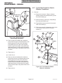
4.3 Shrouds Removal / Installation (Applies to Units With Serial Numbers
AV-2889 Thru Present and DJ-1000
Thru Present)
A. Removal
(1) If possible, raise TILT UP function all the way
up.
WARNING
Always disconnect the power cord
from the wall outlet before removing
any of the table's covers / shrouds or making any
repairs to prevent the possibility of electrical
shock. Failure to comply with these instructions
could result in severe personal injury or death.
OPERATOR'S
CONSOLE
4
3
MA302300
Figure 4-2. Shrouds Removal / Installation
(2) Unplug table power cord from wall outlet.
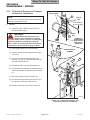
NOTE
(3) Remove six screws (1, Figure 4-2) and cover
(2) from R.H. and L.H. shrouds (3).
Remove stirrup housing from side of table which
does not have operator's console.
(4) Remove three screws (4) securing R.H. and
L.H. shrouds (3) together.
© Midmark Corporation 1995 SF-1492
(5) Remove one screw (5), two screws (6),
lockwashers (7), and stirrup housing (8) from
seat weldment (9).
Page 4-2
Printed in U.S.A.
Return To Table Of Contents
SECTION IV
MAINTENANCE / SERVICE
(2) Unplug table power cord from wall outlet.
NOTE
(3) If TABLE UP function cannot be raised all the
way up, remove shrouds (Refer to para 4.2 or
4.3).
Remove shroud from side of table which does not
have operator's console.
(6) Remove two screws (10) and either L.H. or
R.H. shroud (3) from inner member weldment (11).
(4) Remove two screws (1, Figure 4-3) and back
lower shroud (2) from L.H. and R.H support
channels (3).
B. Installation
(5) Tag and disconnect four wire harnesses (4)
from connectors of interface board (5).
(1) Coat threads of two screws (10) with removable
threadlocking adhesive (Loctite 242).
(6) Tag and disconnect three wires (6) from
terminals of interface board (5).
(2) Install shroud (3) on inner member weldment
(11) and secure with two screws (10).
(7) Remove four screws (7), starwashers (8),
interface board (5), and spacers (9) from
brace (10).
(3) Secure L.H. and R.H. shrouds (3) together with
three screws (4).
B. Installation
(4) Install stirrup housing (8) on seat weldment (9)
and secure with two lockwashers (7), screws
(6), and one screw (5).
NOTE
Four new standoffs, starwashers, and screws are
supplied with the new interface board kit.
(5) Install cover (2) on R.H. and L.H. shrouds (3)
and secure with six screws (1).
(1) Install four new standoffs (11) on brace (10) by
installing standoffs into original mounting holes
for interface board.
(6) Plug table power cord into wall outlet.
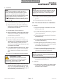
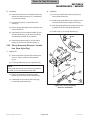
4.4 Interface Board Removal / Installation
(Early Units)
NOTE
This procedure applies to units with Serial Number
AV-1000 Thru AV-2217 and also AV-2229, AV-2231,
AV-2236, AV-2238, AV-2244, AV-2247, and AV2248.
(2) Install interface board (5) on standoffs (11) and
secure with four starwashers (8) and new
screws (7).
(3) Connect three wires (6) to terminals of interface
board (5).
(4) Connect four wire harnesses (4) to connectors
of interface board (5).
A. Removal
(1) If possible, raise TABLE UP function all the way
up.
WARNING
(5) Install back lower shroud (2) on L.H. and R.H.
support channels (3) and secure with two
screws (1), making sure locator pins are
inserted thru locator holes of back lower
shroud.
Always disconnect the power cord
from the wall outlet before removing
any of the table's covers / shrouds or making any
repairs to prevent the possibility of electrical
shock. Failure to comply with these instructions
could result in severe personal injury or death.
© Midmark Corporation 1995 SF-1492
Page 4-3
Printed in U.S.A.
Return To Table Of Contents
SECTION IV
MAINTENANCE / SERVICE
9
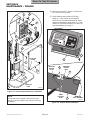
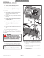
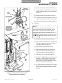
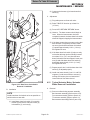
(6) Remove two screws (1, Figure 4-4) and lower
the console cover (2) down.
11
(7) Check Midmark part number on PC logic
board (3). If part number is 015-0460-00
Revision A or 015-0460-00 Revision B, install
adapter as described in steps 8 thru 10. If part
number is 015-0460-00 Revision C or later , do
not install adapter; go to step 11.
8
7
8
4
1 2
3 4
5 6
7 8
10
6
5
4
3
1
LOCATOR
HOLES
2
1
ADAPTER
BOARD
PLUG
2
5
ADAPTER
BOARD
PORT
4
015-0
REVIS 460-00
ION "X
"
3
LOCATOR
PINS
MA302400
Figure 4-3. Interface Board Removal / Installation
HAND
CONTROL
PORT
NOTE
The console cover is hinged. After removing two
screws (3), the front edge of the console cover may
be lowered.
© Midmark Corporation 1995 SF-1492
3
MIDMARK
PART NUMBER
MA302500
Figure 4-4. Adapter Board Installation
Page 4-4
Printed in U.S.A.
Return To Table Of Contents
SECTION IV
MAINTENANCE / SERVICE
(8) Disconnect modular cord (4) from hand control
port of PC logic board (3).
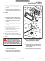
(4) Remove two screws (1, Figure 4-5) and back
lower shroud (2) from L.H. and R.H support
channels (3).
NOTE
(5) Tag and disconnect four wire harnesses (4)
from connectors of interface board (5).
Adapter board is supplied with the interface board kit.
(9) Connect plug of adapter board (5) into hand
control port of PC logic board (3).
8
(10) Plug modular cord (4) into port of adapter
board (5).
8
(11) Close console cover (2) and secure in this
position with two screws (1).
7
4
9
(12) If removed, install shrouds (Refer to
para 4.2 or 4.3).
(13) Plug table power cord into wall outlet.
11
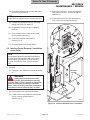
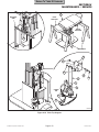
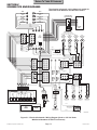
4.5 Interface Board Removal / Installation
(Later Units)
6
5
4
NOTE
This procedure applies to units with Serial Number
AV-2218 Thru Present and DJ-1000 Thru Present
with the following exceptions: AV-2229, AV-2231,
AV-2236, AV-2238, AV-2244, AV-2247, and AV2248.
3
A. Removal
(1) If possible, raise TABLE UP function all the way
up.
LOCATOR
HOLES
1
WARNING
Always disconnect the power cord
from the wall outlet before removing
any of the table's covers / shrouds or making any
repairs to prevent the possibility of electrical
shock. Failure to comply with these instructions
could result in severe personal injury or death.
2
(2) Unplug table power cord from wall outlet.
(3) If TABLE UP function cannot be raised all the
way up, remove shrouds (Refer to
para 4.2 or 4.3).
3
LOCATOR
PINS
MA302600
Figure 4-5. Interface Board Removal / Installation
© Midmark Corporation 1995 SF-1492
Page 4-5
Printed in U.S.A.
Return To Table Of Contents
SECTION IV
MAINTENANCE / SERVICE
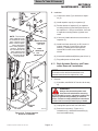
(6) Tag and disconnect three wires (6) from
terminals of interface board (5).
(7) Remove four screws (7), eight starwashers (8),
and interface board (5) from standoffs (9).
1 2
3 4
5 6
7 8
B. Installation
(1) Install interface board (5) on standoffs (9) and
secure with eight starwashers (8) and
screws (7).
(2) Connect three wires (6) to terminals of interface
board (5).
(3) Connect four wire harnesses (4) to connectors
of interface board (5).
3
2
(4) Install back lower shroud (2) on L.H. and R.H.
support channels (3) and secure with two
screws (1), making sure locator pins are
inserted thru locator holes of back lower
shroud.
HAND
CONTROL
PORT
(5) If removed, install shrouds (Refer to para 4.2 or
4.3).
1
9
5
6
(6) Plug table power cord into wall outlet.
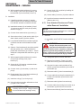
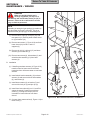
4.6 PC Logic Board Removal / Installation
8
A. Removal
WARNING
Always disconnect the power cord
from the wall outlet before removing
any of the table's covers / shrouds or making any
repairs to prevent the possibility of electrical
shock. Failure to comply with these instructions
could result in severe personal injury or death.
4
2
10
MA302700
Figure 4-6. PC Logic Board Removal / Installation
(1) Unplug table power cord from wall outlet.
(2) Disconnect hand control coil cord (1, Figure 46) from hand control port of PC logic board (2).
(3) Remove two screws (3) and then lower console
cover (4).
(4) Tag and disconnect four transmitter wires (5)
from PC logic board (2).
NOTE
The console cover is hinged. After removing two
screws, console cover should be able to be lowered.
© Midmark Corporation 1995 SF-1492
11
7
(5) Tag and disconnect four receiver wires (6) from
PC logic board (2).
Page 4-6
Printed in U.S.A.
Return To Table Of Contents
SECTION IV
MAINTENANCE / SERVICE
(6) Disconnect ribbon connector (7), modular cord
(8), and wire harness (9) from PC logic
board (2).
3
4
2
(7) Remove four screws (10), starwashers (11),
and PC logic board (2) from console cover (4).
1
5
5
B. Installation
2
6
3
7
4
8
1
(1) Install PC logic board (2) on console cover (4)
and secure with four starwashers (11) and
screws (10).
RIBBON
CABLE
7
(2) Connect wire harness (9), modular cord (8),
and ribbon connector (7) to PC logic board (2).
(3) Connect four receiver wires (6) to PC logic
board (2).
8
(4) Connect four transmitter wires (5) to PC logic
board (2).
6
9
10
(5) Close console cover (4) and secure in this
position with two screws (3).
RIBBON
CABLE
(6) Connect hand control coil cord (1) to hand
control port of PC logic board (2).
11
5
(7) Plug table power cord into wall outlet.
4.7 Program Panel or Program Panel
Interface Board Removal / Installation
A. Removal
RIBBON
CABLE
MA302800
WARNING
Figure 4-7. Program Panel or Program Panel
Interface Board Removal / Installation
Always disconnect the power cord
from the wall outlet before removing
any of the table's covers / shrouds or making any
repairs to prevent the possibility of electrical
shock. Failure to comply with these instructions
could result in severe personal injury or death.
(4) Disconnect ribbon cable of program panel
interface board (6) from PC logic board (7).
(5) Disconnect two wires (8) from program panel
interface board (6) and then remove program
panel (5) from table.
(1) Unplug table power cord from wall outlet.
(2) Remove four screws (1, Figure 4-7) and bezel
(2) from console weldment (3).
(6) Disconnect ribbon cable of program panel (5)
from program panel interface board (6).
(3) Remove six screws (4) and partially remove
program panel (5) from console weldment (3).
© Midmark Corporation 1995 SF-1492
Page 4-7
Printed in U.S.A.
Return To Table Of Contents
SECTION IV
MAINTENANCE / SERVICE
NOTE
6
Newer program panel interface boards do not have
spacers (11) and lockwashers (10).
5
(7) Remove three locknuts (9) and program panel
interface board (6) from program panel (5) or
remove three nuts (9), lockwashers (10),
program panel interface board (6), and spacers
(11) from program panel (5).
2
3
SLOT
"A"
RIBBON
CONNECTOR
B. Installation
NOTE
4
If replacing an old style program panel interface
board (does not have standoffs) with a new style
program panel interface board (has standoffs),
discard spacers; they are not necessary.
7
SLOT
"B"
1
(1) Install program panel interface board (6) on
program panel (5) and secure with three
locknuts (9) or three spacers (11), lockwashers
(10) and nuts (9).
8
(2) Connect ribbon cable of program panel (5) to
program panel interface board (6).
MA302900
Figure 4-8. Hand Control Panel or Hand Control
Board Removal / Installation
(3) Connect two wires (8) to program panel interface board (6).
(2) Remove two screws (2) and top end cap (3)
from hand control tube (4).
(4) Connect ribbon cable of program panel interface board (6) to PC logic board (7).
(3) Remove spacer plate (5) from hand control
tube (4).
(5) Install program panel (5) on console weldment
(3) and secure with six screws (4).
(4) Remove hand control panel (6) and hand
control board (7) as an assembly from hand
control tube (4).
(6) Install bezel (2) on console weldment (3) and
secure with four screws (1).
(5) Disconnect ribbon connector of hand control
panel (6) from hand control board (7).
(7) Plug table power cord into wall outlet.
4.8 Hand Control Panel or Hand Control
Board Removal / Installation
B. Installation
(1) Connect ribbon connector of hand control panel
(6) to hand control board (7).
A. Removal
(1) Disconnect coil cord (1, Figure 4-8) from hand
control.
© Midmark Corporation 1995 SF-1492
(2) Make sure fishpaper insulator (8) is on the
bottom of hand control tube (4).
Page 4-8
Printed in U.S.A.
Return To Table Of Contents
SECTION IV
MAINTENANCE / SERVICE
(3) Simultaneously, slide hand control panel (6)
into slot A and hand control board (7) into slot B
of hand control tube (4).
1
(4) Install spacer plate (5) into slot B of hand
control tube (4).
(5) Install top end cap (3) on hand control tube (4)
and secure with two screws (2).
2
(6) Connect coil cord (1) to hand control.
17
4.9 Pan Safety Limit Switch Removal /
Installation
10
11
12
A. Removal
7
13
16
14
WARNING
15
Always disconnect the power cord
from the wall outlet before removing
any of the table's covers / shrouds or making any
repairs to prevent the possibility of electrical
shock. Failure to comply with these instructions
could result in severe personal injury or death.
9
(1) Unplug table power cord from wall outlet.
8
5
(2) Remove upholstered seat (1, Figure 4-9) from
seat board assembly (2).
6
NOTE
4
Removal of latest version of stirrup housing is
shown. Removal of early versions of stirrup housing
is similar.
PAN HOLDER
ASSEMBLY
(3) Remove one screw (3), two screws (4),
lockwashers (5), and stirrup housing (6) from
each side of seat weldment (7).
3
ACCESS
HOLES
MA303000
Figure 4-9. Pan Safety Limit Switch Removal /
Installation / Adjustment
(6) Disconnect two wires (10) from pan safety limit
switch (11).
(4) Remove four screws (8), lockwashers (9), and
seat board assembly (2) from seat weldment (7).
(7) Remove two screws (12), lockwashers (13),
washers (14) and switch bracket (15) from seat
weldment (7).
NOTE
If necessary, install a jumper wire across two wires
(10) so FOOT DOWN function may be lowered.
(8) Remove two nuts (16), screws (17), and pan
safety limit switch (11) from switch bracket (15).
(5) Run FOOT DOWN function all the way down.
© Midmark Corporation 1995 SF-1492
Page 4-9
Printed in U.S.A.
Return To Table Of Contents
SECTION IV
MAINTENANCE / SERVICE
B. Installation
4.10 Typical Capacitor Removal / Installation
(1) Install pan safety limit switch (11) on switch
bracket (15) and secure with two screws (17)
and nuts (16).
A. Removal
(2) Install switch bracket (15) on seat weldment (7)
and secure with two washers (14), lockwashers
(13), and screws (12). Do not tighten screws
(12) fully.
(3) Push pan holder assembly inward until it locks
into its fully stowed position.
(4) Connect one wire (10) to N.O. terminal of pan
safety limit switch (11) and other wire (10) to
COM. terminal of pan safety limit switch.
(1) If possible, raise TABLE UP function all the way
up.
WARNING
Always disconnect the power cord
from the wall outlet before removing
any of the table's covers / shrouds or making any
repairs to prevent the possibility of electrical
shock. Failure to comply with these instructions
could result in severe personal injury or death.
(2) Unplug table power cord from wall outlet.
EQUIPMENT ALERT
(3) Remove shrouds as necessary (Refer to para
4.2 or 4.3).
Adjust pan safety limit switch so only trip
arm of limit switch makes contact with pan
holder assembly when it is closed; otherwise damage to limit switch could occur from pan holder
assembly "slamming" into the limit switch.
(4) Remove two screws (1, Figure 4-10) and back
lower shroud (2) from R.H. and L.H. support
channels (3).
(5) Slide switch bracket (15) toward rear panel of
pan holder assembly until trip arm of pan safety
limit switch (11) is firmly tripped by pan holder
assembly. Tighten two screws (12).
(5) If necessary, cut any cable ties securing wires
to capacitor being removed.
(6) Using a screwdriver, pry tab of capacitor
mounting bracket (4) upward and remove
capacitor (5) from capacitor mounting bracket.
(6) Install seat board assembly (2) on seat
weldment (7) and secure with four lockwashers
(9) and screws (8).
(7) Remove capacitor cap (6) from capacitor (5).
NOTE
Installation of latest version of stirrup housing is
shown. Installation of early versions of stirrup
housing is similar.
(7) Install one stirrup housing (6) on each side of
seat weldment (7) and secure with two
lockwashers (5), screws (4), and screw (3).
WARNING
A capacitor contains stored electricity.
Never touch terminals of a capacitor,
even if power has been shut off or disconnected.
Always discharge capacitor before touching
capacitor terminals or wires. Failure to comply
with these instruction could result in serious
personal injury or death.
(8) Install upholstered seat (1) on seat board
assembly (2).
(8) Discharge capacitor (5).
(9) Plug table power cord into wall outlet.
(9) Disconnect two wires (7) from terminals of
capacitor (5).
© Midmark Corporation 1995 SF-1492
Page 4-10
Printed in U.S.A.
Return To Table Of Contents
SECTION IV
MAINTENANCE / SERVICE
B. Installation
CATCH
(1) Connect two wires (7) to terminals of capacitor (5).
TAB
4
5
(2) Install capacitor cap (6) on capacitor (5).
7
LOCATION
VIEW
(3) Position bottom of capacitor (5) on capacitor
mounting bracket (4) and then push the top of
the capacitor in. Using a screwdriver, force tab
of capacitor mounting bracket (4) down over
catch.
6
NOTE: The foot and
back capacitors may
be switched on some
units. Check the wire
colors of these capacitors to determine
foot or back capacitor
location. Red wires
are connected to the
back capacitor and
the yellow wires are
connected to the
foot capacitor.
(4) If removed, install cable ties to secure wires to
capacitor (5).
BACK OR FOOT
CAPACITOR
(See Note)
(5) Install back lower shroud (2) on R.H. and L.H.
support channels (3) and secure with two
screws (1), making sure locator pins are
inserted thru locator holes of back lower
shroud.
BASE
CAPACITOR
TILT
CAPACITOR
(6) If removed, install shrouds (Refer to para 4.2 or 4.3).
(7) Plug table power cord into outlet.
4.11
Back Actuator Receiver and Transmitter Removal / Installation
NOTE
The back receiver and back transmitter are a
matched set and must be replaced as a set.
LOCATOR
HOLES
A. Removal
1
(1) If possible, raise BACK UP function all the way
up.
3
WARNING
2
3
Always disconnect the power cord
from the wall outlet before removing
any of the table's covers / shrouds or making any
repairs to prevent the possibility of electrical
shock. Failure to comply with these instructions
could result in severe personal injury or death.
(2) Unplug table power cord from wall outlet.
LOCATOR
PINS
MA303100
Figure 4-10. Typical Capacitor
Removal / Installation
© Midmark Corporation 1995 SF-1492 Rev. 4/97
Page 4-11
(3) Remove four screws (1, Figure 4-11),
lockwashers (2), and backrest assembly (3)
from back weldment (4).
Printed in U.S.A.
Return To Table Of Contents
SECTION IV
MAINTENANCE / SERVICE
(4) Use pencil or tape to mark positions of back
receiver (5) and back transmitter (6) on back
actuator (7).
(5) Disconnect cable (8) from back transmitter (6).
(6) Cut two cable ties securing back transmitter (6)
to shaft of back actuator (7) and remove back
transmitter.
CABLE
TIES
5
(7) Disconnect cable (9) from back receiver (5).
ALIGN BACK
TRANSMITTER
WITH SOUND
TUBE OF BACK
RECEIVER
CABLE
TIES
(8) Cut three cable ties securing back receiver (5)
to back actuator (7) and remove back receiver.
6
TAPE OR
PENCIL MARK
(9) Remove sound tube (10) from back receiver (5).
3/16" TO 5/16"
(4.7 TO 7.9 mm)
B. Installation
XXXRXXXXXX
XX
5
NOTE
If you become uncertain as to which part is the
receiver and which part is the transmitter, remove
the receiver or transmitter from its black plastic
mounting bracket and check its identification number
(located on side of receiver or transmitter). An
EFRRTB40K2 number indicates the part is a receiver
while an EFROTB40K2 number indicates the part is
a transmitter.
IDENTIFICATION
NUMBER
10
1
2
(1) Install sound tube (10) on back receiver (5).
4
(2) Align back receiver (5) with mark (made during
removal) on back actuator (7) and secure in
this position with three cable ties.
(3) Connect cable (9) to back receiver (5).
9
3
5
6
(4) Align back transmitter (6) with mark (made
during removal) on back actuator (7) and
secure in this position with two cable ties.
7
(5) Connect cable (8) to back transmitter (6).
(6) Carefully run BACK UP function all the way up
and then run BACK DOWN function all the way
down, while watching to make sure the back
receiver (5) or back transmitter (6) does not
come into contact with anything.
8
MA303200
Figure 4-11. Back Actuator Receiver and
Transmitter Removal / Installation
© Midmark Corporation 1995 SF-1492
Page 4-12
Printed in U.S.A.
Return To Table Of Contents
SECTION IV
MAINTENANCE / SERVICE
(7) If it is determined that contact will occur, adjust
both the back receiver (5) and / or back transmitter (6) as determined necessary to correct
situation.
6
PILOT
HOLE
1/8"
DRILL
BIT
(8) Lower BACK DOWN function all the way down.
EQUIPMENT ALERT
The alignment of the back receiver and
back transmitter is critical to the programming function. Failure to do so could result in
programming operation malfunction.
14
13
12
(9) Slide back transmitter (6) up or down shaft of
back actuator (7) until back transmitter is 3/16
to 5/16 in. (4.7 to 7.9 mm) from sound
tube (10). Then rotate back transmitter (6) until
it is directly aligned with sound tube (10) of
back receiver (5).
7
NOTE
8
Because the back receiver and back transmitter may
not be returned exactly to the same position, have
the operator check the integrity of the programmed
positions.
1
(10) Install backrest assembly (3) on back weldment
(4) and secure with four lockwashers (2) and
screws (1).
4.12
10
7
4
Back Actuator Removal / Installation
CABLE
TIE
A. Removal
(1) If possible, lower BACK DOWN function all the
way down.
2
3
5
(2) Remove back actuator transmitter and receiver
(Refer to para 4.11).
7
(3) Cut cable tie securing three wires (1, Figure 412) and receiver cable (2) to shaft of back
actuator (3).
9
CABLE
TIE
(4) Tag and disconnect three wires (1) from
actuator wires (4).
7
11
(5) Cut cable tie securing transmitter cable (5) to
shaft of back actuator (3).
MA303300
Figure 4-12. Back Actuator Removal / Installation
© Midmark Corporation 1995 SF-1492
Page 4-13
Printed in U.S.A.
Return To Table Of Contents
SECTION IV
MAINTENANCE / SERVICE
(13) Secure clevis (13) in position by installing roll
pin (14) in pilot hole.
(6) While supporting back weldment (6), remove
four e-rings (7), two clevis pins (8 and 9), and
back actuator (3) from brackets (10 and 11).
(14) Secure cable (5) to clevis (13) with a cable tie.
B. Installation
(15) Install back actuator transmitter and receiver
(Refer to para 4.11).
(1) If installing new back actuator (3), transfer
marks for back receiver and back transmitter
from old back actuator to new back actuator.
4.13
(2) Install back actuator (3) on brackets (10 and
11) and secure with two clevis pins (8 and 9)
and four e-rings (7).
Foot Actuator Receiver and Transmitter Removal / Installation
NOTE
The foot receiver and foot transmitter are a matched
set and must be replaced as a set.
(3) Connect three actuator wires (4) to wires (1).
(4) Secure three wires (1) and receiver cable (2) to
shaft of back actuator (3) with a cable tie.
A. Removal
(1) If possible, raise FOOT UP function all the way
up.
(5) Lower BACK DOWN function all the way down
(until back actuator can be heard free wheeling).
(6) Observe. Back weldment (6) should be parallel
with seat section (12). If back weldment is
parallel with seat section, go to step 11. If back
weldment is not parallel with seat section, go to
step 7.
WARNING
Always disconnect the power cord
from the wall outlet before removing
any of the table's covers / shrouds or making any
repairs to prevent the possibility of electrical
shock. Failure to comply with these instructions
could result in severe personal injury or death.
(2) Unplug table power cord from wall outlet.
(7) While supporting back weldment (6), remove
clevis pin (9) securing clevis (13) to
bracket (11).
(3) Remove four screws (1, Figure 4-13), and
plastic foot cover (2) from foot extension (3).
(8) Screw clevis (13) inward or outward as determined necessary in step 6.
(4) Use pencil or tape to mark positions of foot
receiver (4) and foot transmitter (5) on shaft of
foot actuator (6).
(9) Connect clevis (13) to bracket (11) with clevis
pin (9).
(5) Disconnect cable (7) from foot transmitter (5).
(10) Repeat steps 5 thru 10 until back weldment (6)
is parallel with seat section (12).
(11) Install two e-rings (7) on clevis pin (9).
(12) Using pilot hole as a guide, drill hole thru clevis
(13) with a 1/8 in. drill bit.
(6) Cut two cable ties securing foot transmitter (5)
to shaft of foot actuator (6) and remove foot
transmitter.
(7) Disconnect cable (8) from foot receiver (4).
EQUIPMENT ALERT
(8) Cut three cable ties securing foot receiver (4) to
foot actuator (6) and remove foot receiver.
Carefully drive in roll pin. Using excessive
force could bend rod, resulting in noisy
(9) Remove sound tube (9) from foot receiver (4).
operation.
© Midmark Corporation 1995 SF-1492
Page 4-14
Printed in U.S.A.
Return To Table Of Contents
SECTION IV
MAINTENANCE / SERVICE
B. Installation
NOTE
CABLE
TIES
4
CABLE
TIES
TAPE OR
PENCIL MARK
ALIGN FOOT
TRANSMITTER
WITH SOUND
TUBE OF FOOT
RECEIVER
If you become uncertain as to which part is the
receiver and which part is the transmitter, remove
the receiver or transmitter from its black plastic
mounting bracket and check its identification number
(located on side of receiver or transmitter). An
EFRRTB40K2 number indicates the part is a receiver
while an EFROTB40K2 number indicates the part is
a transmitter.
(1) Install sound tube (9) on foot receiver (4).
(2) Align foot receiver (4) with mark (made during
removal) on foot actuator (6) and secure in this
position with three cable ties.
5
3/16" TO 5/16"
(4.7 TO 7.9 mm)
(3) Connect cable (8) to foot receiver (4).
4
XXXRXXXXXX
(4) Align foot transmitter (5) with mark (made
during removal) on foot actuator (6) and secure
in this position with two cable ties.
IDENTIFICATION
NUMBER
(5) Connect cable (7) to foot transmitter (5).
9
(6) Carefully run FOOT UP function all the way up
and then run FOOT DOWN function all the way
down, while watching to make sure the foot
receiver (4) or foot transmitter (5) does not
come into contact with anything.
7
5
4
(7) If it is determined that contact will occur, adjust
both the foot receiver (4) and / or foot transmitter (5) as determined necessary to correct
situation.
9
8
(8) Lower FOOT DOWN function all the way down.
EQUIPMENT ALERT
The alignment of the foot receiver and
foot transmitter is critical to the programming function. Failure to do so could result in
programming operation malfunction.
6
3
(9) Slide foot transmitter (5) up or down shaft of
foot actuator (6) until foot transmitter is 3/16 to
5/16 in. (4.7 to 7.9 mm) from sound tube (9).
Then rotate foot transmitter (5) until it is directly
aligned with sound tube (9) of back receiver (4).
2
1
MA303400
Figure 4-13. Foot Actuator Receiver and
Transmitter Removal / Installation
© Midmark Corporation 1995 SF-1492
Page 4-15
Printed in U.S.A.
Return To Table Of Contents
SECTION IV
MAINTENANCE / SERVICE
(3) Install foot actuator (3) on foot extension (6)
and secure with three screws (10).
NOTE
Because the foot receiver and foot transmitter may
not be returned exactly to the same position, have
the operator check the integrity of the programmed
positions.
(4) Connect clevis (14) to bracket (9) and secure
with clevis pin (8).
(5) Connect three actuator wires (1) to three
wires (4).
(10) Install plastic foot cover (2) on foot extension
(3) and secure with four screws (1).
4.14
(6) Secure three actuator wires (1) to shaft of foot
actuator (3) with cable ties.
Foot Actuator Removal / Installation
(7) Lower FOOT DOWN function all the way down
(until foot actuator can be heard free wheeling).
A. Removal
(1) If possible, raise FOOT UP function all the way
up.
(8) Observe. Foot extension (6) should be parallel
with seat section (15). If foot extension is
parallel with seat section, go to step 13. If foot
extension is not parallel with seat section, go to
step 9.
(2) Remove foot actuator transmitter and receiver
(Refer to para 4.13).
(3) Cut cable ties securing three actuator wires (1,
Figure 4-14) and receiver cable (2) to shaft of
foot actuator (3).
(9) While supporting foot extension (6), remove
clevis pin (8) securing clevis (14) to
bracket (9).
(4) Tag and disconnect three actuator wires (1)
from three wires (4).
(10) Screw clevis (14) inward or outward as determined necessary in step 7.
(5) Cut cable tie securing transmitter cable (5) to
shaft of foot actuator (3).
(11) Connect clevis (14) to bracket (9) with clevis
pin (8).
(6) While supporting foot extension (6), remove
two e-rings (7), clevis pin (8) securing shaft of
foot actuator (3) to bracket (9).
(12) Repeat steps 7 thru 11 until back foot extension
(6) is parallel with seat section (15).
(13) Install two e-rings (7) on clevis pin (8).
(7) While supporting foot extension (6), remove
three screws (10) and foot actuator (3) from
foot extension. Lower foot extension.
(14) Using pilot hole as a guide, drill hole thru clevis
(14) with a 1/8 in. drill bit.
(8) Remove two e-rings (11), clevis pin (12), and
actuator hitch (13) from foot actuator (3).
EQUIPMENT ALERT
Carefully drive in roll pin. Using excessive
force could bend rod, resulting in noisy
B. Installation
operation.
(1) If installing new foot actuator (3), transfer marks
for foot receiver and foot transmitter from old
foot actuator to new foot actuator.
(16) Secure cable (5) to clevis (14) with a cable tie.
(2) Install actuator hitch (13) on foot actuator (3)
and secure with clevis pin (12) and two
e-rings (11).
© Midmark Corporation 1995 SF-1492
(15) Secure clevis (14) in position by installing roll
pin (16) in pilot hole.
(17) Install foot actuator transmitter and receiver
(Refer to para 4.13).
Page 4-16
Printed in U.S.A.
Return To Table Of Contents
SECTION IV
MAINTENANCE / SERVICE
PILOT
HOLE
1/8"
DRILL
BIT
15
14
16
A
6
7
9
8
10
5
3
2
3
11
7
CABLE
TIE
CABLE
TIE
1
4
12
13
A
CABLE
TIE
11
MA303500
Figure 4-14. Foot Actuator Removal / Installation
© Midmark Corporation 1995 SF-1492
Page 4-17
Printed in U.S.A.
Return To Table Of Contents
SECTION IV
MAINTENANCE / SERVICE
4.15
Tilt Actuator Receiver and Transmitter Removal / Installation
TAPE OR
PENCIL MARK
2
NOTE
CABLE
TIES
The tilt receiver and tilt transmitter are a matched set
and must be replaced as a set.
3/16" TO 5/16"
(4.7 TO 7.9 mm)
A. Removal
(1) If possible, raise TABLE UP and FOOT UP
functions all the way up.
WARNING
(2) Unplug table power cord from wall outlet.
1
ALIGN TILT
TRANSMITTER
WITH SOUND
TUBE OF TILT
RECEIVER
2
XXXRXXXXXX
Always disconnect the power cord
from the wall outlet before removing
any of the table's covers / shrouds or making any
repairs to prevent the possibility of electrical
shock. Failure to comply with these instructions
could result in severe personal injury or death.
CABLE
TIES
IDENTIFICATION
NUMBER
(3) Remove shrouds as necessary (Refer to para
4.2 or 4.3).
(4) Use pencil or tape to mark positions of tilt
receiver (1, Figure 4-15) and tilt transmitter (2)
on shaft of tilt actuator (3).
4
(5) Disconnect cable (4) from tilt transmitter (2).
(6) Cut two cable ties securing tilt transmitter (2) to
shaft of tilt actuator (3) and remove tilt transmitter.
2
3
(7) Disconnect cable (5) from tilt receiver (1).
(8) Cut three cable ties securing tilt receiver (1) to
tilt actuator (3) and remove tilt receiver.
6
(9) Remove sound tube (6) from tilt receiver (1).
1
5
MA303600
Figure 4-15. Tilt Actuator Receiver and
Transmitter Removal / Installation
© Midmark Corporation 1995 SF-1492
Page 4-18
Printed in U.S.A.
Return To Table Of Contents
SECTION IV
MAINTENANCE / SERVICE
B. Installation
NOTE
NOTE
If you become uncertain as to which part is the
receiver and which part is the transmitter, remove
the receiver or transmitter from its black plastic
mounting bracket and check its identification number
(located on side of receiver or transmitter). An
EFRRTB40K2 number indicates the part is a receiver
while an EFROTB40K2 number indicates the part is
a transmitter.
Because the tilt receiver and tilt transmitter may not
be returned exactly to the same position, have the
operator check the integrity of the programmed
positions.
(10) Install shrouds as necessary (Refer to para 4.2
or 4.3).
(11) Plug table power cord into wall outlet.
(1) Install sound tube (6) on tilt receiver (1).
4.16
(2) Align tilt receiver (1) with mark (made during
removal) on tilt actuator (3) and secure in this
position with three cable ties.
A. Removal
Tilt Actuator Removal / Installation
(1) Remove tilt actuator transmitter and receiver
(Refer to para 4.15).
(3) Connect cable (5) to tilt receiver (1).
(2) Cut cable ties securing three wires (1, Figure 416) to tilt actuator (2).
(4) Align tilt transmitter (2) with mark (made during
removal) on tilt actuator (3) and secure in this
position with two cable ties.
(3) Tag and disconnect three wires (1) from three
actuator wires (3).
(5) Connect cable (4) to tilt transmitter (2).
(4) Cut two cable ties securing transmitter cable (4)
to shaft of tilt actuator (2).
(6) Carefully run TILT UP function all the way up
and then run TILT DOWN function all the way
down, while watching to make sure the tilt
receiver (1) or tilt transmitter (2) does not come
into contact with anything.
(5) While supporting foot end of table top, remove
two e-rings (5) and clevis pin (6) securing shaft
of tilt actuator (2) to bracket (7).
(7) If it is determined that contact will occur, adjust
both the tilt receiver (1) and / or tilt transmitter
(2) as determined necessary to correct situation.
(6) Lower tilt actuator (2) down out of way; then
lower foot end of table top downward until it is
resting on inner member weldment (8).
NOTE
(8) Lower TILT DOWN function all the way down.
Clevis pin can only be removed in one direction as
shown in the illustration.
EQUIPMENT ALERT
The alignment of the tilt receiver and
tilt transmitter is critical to the programming function. Failure to do so could result in
programming operation malfunction.
(7) Remove two e-rings (9), clevis pin (10), and tilt
actuator (2) from bracket (11).
B. Installation
(9) Slide tilt transmitter (2) up or down shaft of tilt
actuator (3) until tilt transmitter is 3/16 to 5/16
in. (4.7 to 7.9 mm) from sound tube (6). Then
rotate tilt transmitter (2) until it is directly aligned
with sound tube (6) of tilt receiver (1).
© Midmark Corporation 1995 SF-1492
Page 4-19
(1) If installing new tilt actuator (2), transfer marks
for tilt receiver and tilt transmitter from old tilt
actuator to new tilt actuator.
Printed in U.S.A.
Return To Table Of Contents
SECTION IV
MAINTENANCE / SERVICE
(2) Install tilt actuator (2) on bracket (11) and
secure with clevis pin (10) and two e-rings (9).
6
5
(3) Connect three actuator wires (3) to three
wires (1).
5
7
(4) While lifting up on foot end of table top, connect
shaft of tilt actuator (2) to bracket (7) with clevis
pin (6) and two e-rings (5).
11
CABLE
TIE
4
(5) Secure three wires (1) to tilt actuator (2) with a
cable tie.
2
(6) Secure cable (4) to shaft of tilt actuator (2) with
cable ties.
(7) Install tilt actuator transmitter and receiver
(Refer to para 4.15).
CABLE
TIE
4.17
10
3
1
Base Actuator Receiver and Transmitter Removal / Installation
NOTE
9
The base receiver and base transmitter are a
matched set and must be replaced as a set.
8
A. Removal
(1) If possible, raise TABLE UP and BACK UP
functions all the way up.
WARNING
Always disconnect the power cord
from the wall outlet before removing
any of the table's covers / shrouds or making any
repairs to prevent the possibility of electrical
shock. Failure to comply with these instructions
could result in severe personal injury or death.
(2) Unplug table power cord from wall outlet.
MA303700
Figure 4-16 Tilt Actuator Removal / Installation
(3) Remove shrouds as necessary (Refer to para
4.2 or 4.3).
(4) Remove two screws (1, Figure 4-17) and rear
lower shroud (2) from R.H. and L.H. support
channels (3).
(5) Use pencil or tape to mark positions of base
receiver (4) and base transmitter (5) on shaft of
base actuator (6).
© Midmark Corporation 1995 SF-1492
Page 4-20
Printed in U.S.A.
Return To Table Of Contents
SECTION IV
MAINTENANCE / SERVICE
(6) Disconnect cable (7) from base transmitter (5).
TAPE OR
PENCIL MARK
5
(7) Cut two cable ties securing base transmitter (5)
to shaft of base actuator (6) and remove base
transmitter.
CABLE
TIES
(8) Disconnect cable (8) from base receiver (4).
3/16" TO 5/16"
(4.7 TO 7.9 mm)
(9) Cut three cable ties securing base receiver (4)
to base actuator (6) and remove base receiver.
(10) Remove sound tube (9) from base receiver (4).
CABLE
TIES
B. Installation
6
NOTE
4
ALIGN BASE
TRANSMITTER
WITH SOUND
TUBE OF BASE
RECEIVER
If you become uncertain as to which part is the
receiver and which part is the transmitter, remove
the receiver or transmitter from its black plastic
mounting bracket and check its identification number
(located on side of receiver or transmitter). An
EFRRTB40K2 number indicates the part is a receiver
while an EFROTB40K2 number indicates the part is
a transmitter.
5
XXXXXXRXXX
IDENTIFICATION
NUMBER
(1) Install sound tube (9) on base receiver (4).
7
(2) Align base receiver (4) with mark (made during
removal) on base actuator (6) and secure in
this position with three cable ties.
(3) Connect cable (8) to base receiver (4).
(4) Align base transmitter (5) with mark (made
during removal) on base actuator (6) and
secure in this position with two cable ties.
LOCATOR
HOLES
1
5
(5) Connect cable (7) to base transmitter (5).
3
3
2
9
4
(6) Carefully run TABLE UP function all the way up
and then run TABLE DOWN function all the
way down, while watching to make sure the
base receiver (4) or base transmitter (5) does
not come into contact with anything.
8
(7) If it is determined that contact will occur, adjust
both the base receiver (4) and / or base transmitter (5) as determined necessary to correct
situation.
LOCATOR
PINS
MA303800
Figure 4-17. Base Actuator Receiver and
Transmitter Removal / Installation
© Midmark Corporation 1995 SF-1492
Page 4-21
Printed in U.S.A.
Return To Table Of Contents
SECTION IV
MAINTENANCE / SERVICE
(8) Lower BASE DOWN function all the way down.
EQUIPMENT ALERT
EQUIPMENT ALERT
Slowly and carefully lower base actuator
until table top is resting on supports. Do
not run base actuator until it is in a bind. Damage to
base actuator could result.
The alignment of the base receiver and
base transmitter is critical to the programming function. Failure to do so could result in
programming operation malfunction.
c. Lower TABLE DOWN function until weight
of table top (3) is resting on support bar.
(9) Slide base transmitter (5) up or down shaft of
base actuator (6) until base transmitter is 3/16
to 5/16 in. (4.7 to 7.9 mm) from sound tube (9).
Then rotate base transmitter (5) until it is
directly aligned with sound tube (9) of base
receiver (4).
(3) If support bar is not available, support table top
with supports as described in the following
substeps:
a. Run TABLE UP function to 3/4 full up
position.
NOTE
Because the base receiver and base transmitter may
not be returned exactly to the same position, have
the operator check the integrity of the programmed
positions.
b. Run TILT DOWN function all the way down,
FOOT UP function all the way up and
BACK DOWN function all the way down,
making table top (3) into a flat, horizontal
position.
(10) Install back lower shroud (2) on L.H. and R.H.
support channels (3) and secure with two
screws (1), making sure locator pins are
inserted thru locator holes of back lower
shroud.
c. Place supports under foot section and back
section of table top (3).
EQUIPMENT ALERT
(11) Install shrouds as necessary (Refer to para 4.2
or 4.3).
(12) Plug table power cord into wall outlet.
4.18
Slowly and carefully lower base actuator
until table top is resting on supports. Do
not run base actuator until it is in a bind. Damage to
base actuator could result.
Base Actuator Removal / Installation
A. Removal
d. Lower TABLE DOWN function until weight
of table top (3) is resting on supports or
raise supports up against table top.
(1) Remove base actuator transmitter and receiver
(Refer to para 4.17).
(4) Cut cable tie securing wires to base actuator (4).
(2) If support bar is going to be used to support
weight of table top, perform the following
substeps. Otherwise, go to step 3. See Table
1-2 for special tool.
(5) Tag and disconnect three wires (5) from three
actuator wires (6).
(6) Disconnect wire harness (7) from base down
limit switch (8).
a. Run TABLE UP function all the way up.
b. With TABLE UP function in full up position,
place support bar across top of R.H. and
L.H. supports (1, Figure 4-18). Slide
support bar under tilt bracket (2).
© Midmark Corporation 1995 SF-1492
Page 4-22
Printed in U.S.A.
Return To Table Of Contents
SECTION IV
MAINTENANCE / SERVICE
3
SUPPORT
BAR
FOOT
SECTION
BACK
SECTION
2
1
SUPPORTS
12
9
11
10
4
9
7
8
CABLE
TIE
6
5
MA303900
Figure 4-18 Table Top Support
© Midmark Corporation 1995 SF-1492
Page 4-23
Printed in U.S.A.
Return To Table Of Contents
SECTION IV
MAINTENANCE / SERVICE
3
DANGER
Make sure weight of table top is
securely supported, per step 2 or 3,
and table top will not fall when clevis pin (10) is
removed. Failure to do so will result in serious
injury or death to personnel.
1
2
3
NOTE
LOCATOR
PIN
Depending on strength of gas spring(s), the table top
may raise when clevis pin is removed. This is an
indicator that the gas spring(s) are functioning well.
(7) Remove two e-rings (9), clevis pin (10), and
two spacers (11) securing shaft of base actuator (4) to bracket (12).
(8) Remove two screws (1, Figure 4-19) and front
lower shroud (2) from R.H. and L.H.
supports (3).
LOCATOR
PIN
LOCATOR
HOLES
(9) Remove pin clip (4), clevis pin (5), and base
actuator (6) from bracket (7).
9
8
(10) Remove two screws (8), lockwashers (9), and
switch bracket assembly (10) from base
actuator (6).
B. Installation
(1) If installing new base actuator (6, Figure 4-19),
transfer marks for base receiver and base
transmitter from old base actuator to new base
actuator.
6
10
(2) Install switch bracket assembly (10) on base
actuator (6) and secure with two lockwashers
(9), and screws (8).
6
(3) Install base actuator (6) on bracket (7) and
secure with clevis pin (5) and pin clip (4).
5
7
(4) Install front lower shroud (2) on L.H. and R.H.
support channels (3) and secure with two
screws (1), making sure locator pins are
inserted thru locator holes of front lower
shroud.
MA304000
(5) Connect three actuator wires (6, Figure 4-18) to
three wires (5).
© Midmark Corporation 1995 SF-1492
4
Figure 4-19. Base Actuator Removal / Installation
Page 4-24
Printed in U.S.A.
Return To Table Of Contents
SECTION IV
MAINTENANCE / SERVICE
(6) Connect wire harness (7) to base down limit
switch (8).
(3) Remove two screws (1, Figure 4-20) and rear
lower shroud (2) from R.H. and L.H.
supports (3).
NOTE
(4) Remove two screws (4) and front lower shroud
(5) from R.H. and L.H. supports (3).
Depending on strength of gas spring(s), an assistant
may be required to help lower the table top slightly to
allow alignment of base actuator shaft with bracket.
(5) If support bar is going to be used to support
weight of table top, perform the following
substeps. Otherwise, go to step 6. See Table
1-2 for special tools.
(7) Raise or lower TABLE UP or TABLE DOWN
function as necessary to align shaft of base
actuator (4) with bracket (12).
a. Run TABLE UP function all the way up.
(8) Secure shaft of base actuator (4) to bracket
(12) with two spacers (11), clevis pin (10), and
two e-rings (9).
b. With TABLE UP function in full up position,
place support bar across top of R.H. and
L.H. supports (3). Slide support bar under
tilt bracket (6).
(9) Raise TABLE UP function all the way up.
(10) Remove support bar from under tilt bracket (2)
or remove supports from under foot section
and back section of table top (3).
(11) Secure wires to base actuator (4) with a cable
tie.
EQUIPMENT ALERT
Slowly and carefully lower base actuator
until table top is resting on supports. Do
not run base actuator until it is in a bind. Damage to
base actuator could result.
(12) Install base actuator transmitter and receiver
(Refer to para 4.17).
4.19
c. Lower TABLE DOWN function until weight
of table top (7) is resting on support bar.
Gas Spring(s) Removal / Installation
A. Removal
WARNING
Always disconnect the power cord
from the wall outlet before removing
any of the table's covers / shrouds or making any
repairs to prevent the possibility of electrical
shock. Failure to comply with these instructions
could result in severe personal injury or death.
NOTE
(6) If support bar is not available, support table top
with supports as described in the following
substeps:
a. Run TABLE UP function to 3/4 full up
position.
b. Run TILT DOWN function all the way down,
FOOT UP function all the way up. and
BACK DOWN function all the way down,
making table top (7) into a flat, horizontal
position.
c. Place supports under foot section and back
section of table top (7).
The two special tools that are required to perform
this procedure are included in the repair kit.
(1) Unplug table power cord from wall outlet.
(2) Remove shrouds as necessary (Refer to para
4.2 or 4.3).
© Midmark Corporation 1995 SF-1492
Page 4-25
Printed in U.S.A.
Return To Table Of Contents
SECTION IV
MAINTENANCE / SERVICE
7
FOOT
SECTION
2
SUPPORT
BAR
BACK
SECTION
4
1
6
3
SUPPORTS
5
12
8
13
14
9
10
8
11
MA304100
Figure 4-20 Table Top Support
© Midmark Corporation 1995 SF-1492
Page 4-26
Printed in U.S.A.
Return To Table Of Contents
SECTION IV
MAINTENANCE / SERVICE
(11) While pressing down on end of pry bar to
relieve pressure from clevis pin (2), remove pin
clip (3), clevis pin (2), and two spacers (4).
Then, slowly raise up on pry bar until gas
spring(s) (5) are fully extended and are no
longer under tension. Remove pry bar.
EQUIPMENT ALERT
Slowly and carefully lower base actuator
until table top is resting on supports. Do
not run base actuator until it is in a bind. Damage to
base actuator could result.
(12) Remove pin clip (6), clevis pin (7), spacer(s)
(8), and gas spring(s) (5) from bracket (9).
d. Lower TABLE DOWN function until weight
of table top (7) is resting on supports or
raise supports up against table top.
B. Installation
DANGER
(1) Install rod end of gas spring(s) (5, Figure 4-21)
on bracket (9) and secure with clevis pin (7),
spacer(s) (8), and pin clip (6).
Make sure weight of table top is
securely supported, per step 5 or 6,
and table top will not fall when clevis pin (10) is
removed. Failure to do so will result in serious
injury or death to personnel.
(2) Insert slot of pry bar in cutout of middle member assembly (1).
NOTE
(3) While pressing down on end of pry bar to align
gas spring(s) (5) with bracket (10), install two
spacers (4), clevis pin (2), and pin clip (3) to
secure gas spring(s) to bracket. Remove pry
bar.
Depending on strength of gas spring(s), the table top
may raise when clevis pin is removed. This is an
indicator that the gas spring(s) are functioning well.
(7) Remove two e-rings (8), spacers (9), and clevis
pin (10) which secures shaft of base actuator
(11) to bracket (12).
(8) Disconnect cable (13) from base transmitter (14).
EQUIPMENT ALERT
EQUIPMENT ALERT
Slowly and carefully raise base actuator
while holding shaft of base actuator
stationary, making sure base transmitter (14) does
not contact anything. Failure to do so could result in
damage to base transmitter.
Slowly and carefully lower base actuator
while holding shaft of base actuator
stationary, making sure base transmitter (14) does
not contact anything. Failure to do so could result in
damage to base transmitter.
(9) While holding shaft of base actuator (11)
stationary (so it cannot rotate), lower TABLE
DOWN function until base actuator is fully
retracted.
(4) While holding shaft of base actuator (11, Figure
4-20) stationary (so it cannot rotate), raise
TABLE UP function until shaft of base actuator
is aligned with bracket (12).
NOTE
Depending on strength of gas spring(s), an assistant
may be required to help lower the table top slightly to
allow alignment of base actuator shaft with bracket.
(5) Secure shaft of base actuator (11) to bracket
(12) with two spacers (9), clevis pin (10), and
two e-rings (8).
(10) Insert slot of pry bar in cutout of middle member assembly (1, Figure 4-21). See Table 1-2
for special tool.
(6) Raise TABLE UP function all the way up.
© Midmark Corporation 1995 SF-1492
Page 4-27
Printed in U.S.A.
Return To Table Of Contents
SECTION IV
MAINTENANCE / SERVICE
10
(7) Remove support bar from under tilt bracket (6)
or remove supports from under foot section
and back section of table top (7).
SLOT
CUTOUT
(8) Connect cable (13) to base transmitter (14).
PRY
BAR
1
(9) Install front lower shroud (5) on L.H. and R.H.
supports (3) and secure with two screws (4),
making sure locator pins are inserted thru
locator holes of front lower shroud.
4
(10) Install rear lower shroud (2) on L.H. and R.H.
supports (3) and secure with two screws (1),
making sure locator pins are inserted thru
locator holes of front lower shroud.
2
3
(11) Install shrouds as necessary (Refer to para 4.2
or 4.3).
5
10
(12) Plug table power cord into wall outlet.
4.20
Base Down Limit Switch Removal /
Installation
A. Removal
8
(1) Raise TABLE UP function all the way up.
5
WARNING
6
Always disconnect the power cord
from the wall outlet before removing
any of the table's covers / shrouds or making any
repairs to prevent the possibility of electrical
shock. Failure to comply with these instructions
could result in severe personal injury or death.
7
(2) Unplug table power cord from wall outlet.
9
(3) Remove two screws (1, Figure 4-22) and rear
lower shroud (2) from R.H. and L.H.
supports (3).
MA304200
Figure 4-21. Gas Spring(s) Removal / Installation
(4) Disconnect wire harness (4) from base down
limit switch (5).
(5) Remove two nuts (6), lockwashers (7), screws
(8), and base down limit switch (5) from switch
bracket (9).
© Midmark Corporation 1995 SF-1492
Page 4-28
Printed in U.S.A.
Return To Table Of Contents
SECTION IV
MAINTENANCE / SERVICE
(2) Connect wire harness (4) to base down limit
switch (5).
6
C. Adjustment
9
(1) Plug table power cord into wall outlet.
4
(2) Raise TABLE UP function up at least 6 in.
(15.2 cm).
8
(3) Press AUTO RETURN "RETURN" button.
7
(4) Observe. The base actuator should begin to
lower. When the base actuator is almost
completely lowered, the base down limit switch
should be tripped, stopping the base actuator.
5
(5) If the base actuator does not stop running after
base actuator is completely lowered, loosen
two nuts (6) and slide base down limit switch
(5) upward approximately 1/16 in. (1.6 mm);
then tighten two nuts.
(6) If the base down limit switch (5) trips too early
so that the table top can be manually lowered
more than 1/2 in. (12.7 mm) after the base
down limit switch has been tripped, loosen two
nuts (6) and slide base down limit switch (5)
downward approximately 1/16 in. (1.6 mm);
then tighten two nuts.
LOCATOR
HOLES
1
3
(7) Repeat steps 2 thru 6 until the base down limit
switch (5) is adjusted properly.
2
(8) Install rear lower shroud (2) on L.H. and R.H.
supports (3) and secure with two screws (1),
making sure locator pins are inserted thru
locator holes of front lower shroud.
LOCATOR
PINS
3
MA304300
4.21
Figure 4-22. Base Down Limit Switch
Removal / Installation
Typical Actuator Motor / Actuator
Brake Removal / Installation
A. Removal
B. Installation
(1) Remove malfunctioning actuator assembly:
Back actuator assembly (Refer to para 4.12).
Foot actuator assembly (Refer to para 4.14).
Tilt actuator assembly (Refer to para 4.16).
Base actuator assembly (Refer to para 4.18).
NOTE
Install base down limit switch as low as possible on
switch bracket to start with.
(1) Install base down limit switch (5) on switch
bracket (9) and secure with two screws (8),
lockwashers (7), and nuts (6).
© Midmark Corporation 1995 SF-1492
Page 4-29
Printed in U.S.A.
Return To Table Of Contents
SECTION IV
MAINTENANCE / SERVICE
(2) Remove two nuts (1, Figure 4-23) and actuator
motor (2) from actuator mechanism (3).
1
(3) Remove two shoulder washers (4) from actuator mechanism (3).
4
(4) Remove spacer (5) and motor coupler (6) from
shaft of actuator motor (2).
KEYS
NOTE
6
A needle nose pliers should be used to extract the
actuator brake from the actuator mechanism. Grasp
the raised round plate of the actuator brake with the
pliers and pull.
3
KEY
SLOTS
(5) Remove actuator brake (7) and rubber damper
(8) from shaft of actuator mechanism (3).
B. Installation
2
8
NOTE
7
The rubber damper must be installed so its flat side
faces the inside of the actuator mechanism. The
actuator brake must be installed so its flattest side
faces outward. The shaft of the actuator mechanism
may be turned with a screwdriver to help align the
keys of the actuator mechanism shaft with the key
slots in actuator brake.
KEY
SLOT
5
MA304400
Figure 4-23. Actuator Motor / Actuator Brake
Removal / Installation
(6) Check actuator assembly for proper operation.
The actuator assembly should run normally and
should not make a grinding noise; this indicates
that key slots of motor coupler were not aligned
properly with keys of actuator mechanism (the
grinding noise also indicates that the motor
coupler is being damaged). The actuator
assembly should brake properly.
(1) Install rubber damper (8), actuator brake (7),
and spacer (5) in actuator mechanism (3).
(2) Install motor coupler (6) on shaft of actuator
motor (2).
(3) Install two shoulder washers (4) in actuator
mechanism (3).
4.22
(4) Align keys of actuator mechanism (3) shaft with
key slots of motor coupler (6) and then install
actuator motor (2) on actuator mechanism (3)
and secure with two nuts (1).
Chain Assembly Adjustment
A. Adjustment
(1) Raise TABLE UP function all the way up.
(2) Unplug table power cord from wall outlet.
(5) Install actuator assembly:
Back actuator assembly (Refer to para 4.12).
Foot actuator assembly (Refer to para 4.14).
Tilt actuator assembly (Refer to para 4.16).
Base actuator assembly (Refer to para 4.18).
(3) Remove two screws (1, Figure 4-24) and front
lower shroud (2) from L.H. and R.H. support
channels (3).
(4) Loosen four screws (4).
© Midmark Corporation 1995 SF-1492
Page 4-30
Printed in U.S.A.
Return To Table Of Contents
SECTION IV
MAINTENANCE / SERVICE
(6) Install front lower shroud (2) on L.H. and R.H.
support channels (3) and secure with two
screws (1), making sure locator pins are
inserted thru locator holes of front lower
shroud.
3
1
2
(7) Plug table power cord into outlet.
3
4.23
LOCATOR
PIN
Headrest Adjustment (Old Style
Headrest)
A. Adjustment
(1) Unlock the lock handle (See Figure 4-25).
(2) Loosen setscrew (1, Figure 4-25).
(3) Tighten adjusting screw (2) slightly; then lock
the lock handle. Repeat this step until Axis A
has the strongest possible holding power, but
operation of lock handle is not too difficult.
LOCATOR
PIN
LOCATOR
HOLES
(4) Tighten setscrew (1).
4
(5) Unlock the lock handle.
6
(6) Loosen setscrew (3).
(7) Tighten adjusting screw (4) slightly; then lock
the lock handle. Repeat this step until Axis B
has the strongest possible holding power, but
operation of lock handle is not too difficult.
6
5
ADJUSTMENT
GAP
(8) Tighten setscrew (3).
(9) Lower BACK DOWN function all the way down.
MA304500
Figure 4-24. Chain Assembly Adjustment
EQUIPMENT ALERT
Adjust chains so they are tight, yet
have a slight spring back. Also, adjust
chains so there is an equal amount of tension on
each chain. Failure to do so will result in chains
loosening earlier and uneven wear.
NOTE
The maximum force required to unclamp a locking
handle should be 17 lbs. (7.7 kg) and the maximum
force required to clamp a locking handle should be
35 lbs. (15.8 kg).
(10) Position headrest assembly as shown in TEST
SETUP.
(11) Place a 45 lb. (20.4 kg) weight on headrest
assembly at Point C.
(5) Insert a pry bar or large screwdriver into
adjustment gap and pry downward on idler
adjustment weldment (5) until chains (6) are
tight, but not drum tight. Tighten four
screws (4).
© Midmark Corporation 1995 SF-1492
Page 4-31
Printed in U.S.A.
Return To Table Of Contents
SECTION IV
MAINTENANCE / SERVICE
4.24
BACK
SECTION
Headrest Handles Handle Stops
Adjustment (Old Style Headrest)
A. Adjustment
POINT
"C"
(1) Lock the locking handle (1, Figure 4-26).
(2) While applying pressure on locking handle (1),
adjust setscrew (2) in or out until there is a 1/8
in. (3.2 mm) between top of lock handle (1) and
headlock bar (3).
HEADREST
ASSEMBLY
TEST
SETUP
1/8"
(3.2mm)
3
1
4
3
1
2
2
AXIS
"B"
LOCK
HANDLE
AXIS
"A"
MA304600
MA304700
Figure 4-25. Headrest Adjustment
Figure 4-26. Headrest Handles
Handle Stops Adjustment
WARNING
Failure to adjust headrest assembly to
specifications could result in a failure
during a procedure. This could cause severe
personal injury to a patient or the need to terminate the procedure.
(12) Observe. The headrest assembly should
support the test weight without drifting downward. If not, repeat entire adjustment procedure. If headrest assembly does not meet test
standards, do not use headrest assembly.
© Midmark Corporation 1995 SF-1492
Page 4-32
Printed in U.S.A.
Return To Table Of Contents
SECTION IV
MAINTENANCE / SERVICE
4.25
Headrest Adjustment (New Style
Headrest)
BACK
SECTION
A. Adjustment
POINT
"D"
(1) Unlock upper lock handle (See Figure 4-27).
(2) Loosen setscrew (1, Figure 4-27).
HEADREST
ASSEMBLY
(3) Tighten adjusting screw (2) slightly; then lock
upper lock handle. Repeat this step until Axis A
and B have the strongest possible holding
power, but operation of upper lock handle is not
too difficult.
TEST
SETUP
1
4
(4) Tighten setscrew (1).
3
2
(5) Unlock lower lock handle.
(6) Loosen setscrew (3).
UPPER LOCK
HANDLE
(7) Tighten adjusting screw (4) slightly; then lock
lower lock handle. Repeat this step until Axis C
has the strongest possible holding power, but
operation of lower lock handle is not too
difficult.
AXIS
"B"
(8) Tighten setscrew (3).
AXIS
"A"
(9) Lower BACK DOWN function all the way down.
LOWER LOCK
HANDLE
AXIS
"C"
NOTE
The maximum force required to unclamp a locking
handle should be 17 lbs. (7.7 kg) and the maximum
force required to clamp a locking handle should be
35 lbs. (15.8 kg).
MA304800
Figure 4-27. Headrest Adjustment
(12) Observe. The headrest assembly should
support the test weight without drifting downward. If not, repeat entire adjustment procedure. If headrest assembly does not meet test
standards, do not use headrest assembly.
(10) Position headrest assembly as shown in TEST
SETUP.
(11) Place a 45 lb. (20.4 kg) weight on headrest
assembly at Point D.
4.26
WARNING
Failure to adjust headrest assembly to
specifications could result in a failure
during a procedure. This could cause severe
personal injury to a patient or the need to terminate the procedure.
© Midmark Corporation 1995 SF-1492
Headrest Handles Handle Stops
Adjustment (New Style Headrest)
A. Adjustment
(1) Loosen nut (1, Figure 4-28).
Page 4-33
Printed in U.S.A.
Return To Table Of Contents
SECTION IV
MAINTENANCE / SERVICE
4.27
2
1
Typical Foot Pedal Foot Switch
Removal / Installation
A. Removal
UPPER LOCK
HANDLE
(1) Remove two screws (1, Figure 4-29) and
partially separate foot switch bracket (2) from
foot control casting (3).
4
3
(2) Remove screw (4), spacer (5), and pedal (6)
from foot switch bracket (2).
(3) Tag and disconnect two wires (7) from terminals of foot switch (8).
(4) Remove two nuts (9), lockwashers (10), screws
(11), and foot switch (8) from foot switch
bracket (2).
LOWER LOCK
HANDLE
6
MA304900
10
Figure 4-28. Headrest Handles
Handle Stops Adjustment
7
9
5
8
(2) Push on upper lock handle until it reaches a
point where the upper lock handle wants to lock
itself by going over center; then allow upper
lock handle to go over center a few degrees.
Hold the upper lock handle in this position and
adjust stop screw (2) so the upper lock handle
will be forced to stop in this position each time it
is locked.
4
PIVOT
SPACER
7
SPRING
SPACER
11
2
(3) Tighten nut (1).
(4) Loosen nut (3).
(5) Push on lower lock handle until it reaches a
point where the lower lock handle wants to lock
itself by going over center; then allow lower
lock handle to go over center a few degrees.
Hold the lower lock handle in this position and
adjust stop screw (4) so the lower lock handle
will be forced to stop in this position each time it
is locked.
1
MA305000
Figure 4-29. Foot Pedal Foot Switch
Removal / Installation
(6) Tighten nut (3).
© Midmark Corporation 1995 SF-1492
3
Page 4-34
Printed in U.S.A.
Return To Table Of Contents
SECTION IV
MAINTENANCE / SERVICE
B. Installation
B. Installation
(1) Install foot switch (8) on foot switch bracket (2)
and secure with two screws (11), lockwashers
(10), and two nuts (9).
(1) If removed, install stirrup index spring (6) on
stirrup guide bracket (4).
(2) Install stirrup guide bracket (4) in stirrup mount
weldment (5) and secure with pivot boss (3).
(2) Connect two wires (7) to terminals of foot
switch (8).
(3) Ensure springs and spacers are in position and
have not fallen off.
(3) Slide stirrup assembly (2) thru slot in pivot boss
(3) and thru slot in stirrup guide bracket (4).
(4) Install screw (1) on stirrup assembly (2).
(4) Install pedal (6) on foot switch bracket (2) and
secure with spacer (5) and screw (4) making
sure pedal is mounted on pivot spacer.
SLOTS
(5) Install foot switch bracket (2) on foot control
casting (3) and secure with two screws (1).
4.28
Stirrup Assembly Removal / Installation (New Style Only)
A. Adjustment
3
(1) Insert screwdriver in access hole and remove
screw (1, Figure 4-30) from stirrup assembly (2).
1
(2) Pull stirrup assembly (2) out of pivot boss (3).
ACCESS
HOLES
NOTE
Stirrup guide bracket (4) is too wide to removed thru
front side; it must be removed out back side.
5
4
(3) Remove pivot boss (3) and stirrup guide
bracket (4) from stirrup mount weldment (5).
(4) If damaged, remove stirrup index spring (6)
from stirrup guide bracket (4).
2
6
MA305100
Figure 4-30. Stirrup Assembly
Removal / Installation
© Midmark Corporation 1995 SF-1492
Page 4-35
Printed in U.S.A.
Return To Table Of Contents
SECTION IV
MAINTENANCE / SERVICE
© Midmark Corporation 1995 SF-1492
Page 4-36
Printed in U.S.A.
Return To Table Of Contents
SECTION V
SCHEMATICS AND DIAGRAMS
SECTION V
SCHEMATICS AND DIAGRAMS
5.1 Electrical Schematics / Wiring
Diagrams
Figure 5-1 illustrates the logic / current flow and wiring
connections between the electrical components in the
115 VAC domestic table. Figure 5-2 illustrates the logic
/ current flow and wiring connections between the
electrical components in the 220 VAC export table.
See next page for Illustration
© Midmark Corporation 1995 SF-1492
Page 5-1
Printed in U.S.A.
Return To Table Of Contents
SECTION V
SCHEMATICS AND DIAGRAMS
The electrical schematic / wiring diagram is similar for
Units with Serial Numbers AV-1000 Thru AV2217
BASE
BASE
RECEIVER
TRANSMITTER
FOOT
FOOT
RECEIVER
TRANSMITTER
BACK
BACK
RECEIVER
TRANSMITTER
TILT
TILT
RECEIVER
TRANSMITTER
PROGRAM PANEL
INTERFACE BOARD
RED
BLUE
WHITE
PROGRAM
PANEL
ORANGE
BASE
J18
15
14
13
15
14
13
BASE
L.E.D.
BLACK
BASE
J11
FOOT
L.E.D.
M
M
M
M
YELLOW (REF)
FOOT
J12
BACK
J13
1
TILT
J14
3
4
6
2
7
5
BLACK
RED
BLACK
WHITE
RED
GRAY
YELLOW
TILT
L.E.D.
WHITE
BACK
L.E.D.
9
10
8
WHITE
BLACK
GREEN
PHONE
PLUG
RED
PAN SAFETY
LIMIT SWITCH (N.O.)
GREEN
8
7
9
8
7
12
11
10
12
11
10
15
14
13
15
14
13
11
15
14
12
11
10
13
15
14
13
5 amp
5 amp
WHITE
RED
WHITE
BLACK
1
4
7
11
2
5
8
11
9
12
3
6
9
12
10
6
10
0.15 amp
PRIMARY
FUSE
CONNECTOR
J3
1
4
7
10
1
4
7
2
5
8
11
2
5
8
11
3
6
9
12
3
6
9
12
INTERFACE
BOARD
6
4
9
7
12
10
WHITE
WHITE
BLACK
10
8
3
GREEN
BLACK
BLACK
HAND
CONTROL
PORT
BASE
CAPACITOR
FOOT
CAPACITOR
BACK
CAPACITOR
TILT
CAPACITOR
53-64 M.F.D.
27-32 M.F.D.
41-53 M.F.D.
53-64 M.F.D.
BLACK
HAND CONTROL
HAND
CONTROL
PANEL
7
5
1
BLACK
RED
WHITE
YELLOW
GREEN
DOWN
UP
TILT
BACK
DOWN
UP
DOWN
UP
DOWN
FOOT
FUSE
GREEN
10
FOOT
TABLE
7
10
FOOT CONTROL
UP
8
5 amp
12
9
4
WHITE
7
5
5 amp
8
6
1
RED
7
4
2
TILT
FUSE
12
9
8
4
3
GREEN
6
3
1
5
9
YELLOW
BROWN
1
BLACK
6
BLUE
PURPLE
2
2
CONNECTOR
J1
3
4
2
3
BLACK
WHITE
RED
ORANGE
1
RED
9
CONNECTOR
J4
RED
4
YELLOW
5
YELLOW
6
ORANGE
4
ORANGE
5
J7
J5
GREEN
6
J6
TABLE
FUSE
1
BACK
FUSE
2
GREEN
3
WHITE
1
CONNECTOR
J2
2
BLACK
3
WHITE
PAN IN = CLOSED CIRCUIT
GRAY
12
11
BLUE
7
10
BLUE
8
11
TILT
ACTUATOR
MOTOR
BLACK
9
12
BACK
ACTUATOR
MOTOR
RED
7
10
FOOT
ACTUATOR
MOTOR
WHITE
8
11
BASE
ACTUATOR
MOTOR
YELLOW
WHITE
BROWN
9
12
PC
LOGIC
BOARD
RED
4
RED
5
WHITE
6
BLACK
4
WHITE
5
BLACK
6
RED
1
WHITE
2
BLACK
3
RED
1
WHITE
2
BASE DOWN
LIMIT SWITCH (N.C.)
TILT
J15
BLACK
YELLOW
BROWN
3
BACK
J16
BASE UP = CLOSED CIRCUIT
(ANY OTHER POSITION = OPEN CIRCUIT)
TRANSMITTER
/ RECEIVER
FUNCTION LED'S
GRAY
RED
WHITE
ORANGE
BLUE
PURPLE
FOOT
J17
CONNECTOR
J10
WHITE
HAND
CONTROL
BOARD
RECEPTACLE
2.5 amps MAX.
POWER CORD
120 V.A.C. 12 amps
60 HZ SUPPLY
WHITE
MA305200
Figure 5-1. Electrical Schematic / Wiring Diagram (Used on 115 VAC Units
With Serial Numbers AV-2218 Thru Present)
© Midmark Corporation 1995 SF-1492
Page 5-2
Printed in U.S.A.
Return To Table Of Contents
SECTION V
SCHEMATICS AND DIAGRAMS
BASE
BASE
RECEIVER
TRANSMITTER
FOOT
FOOT
RECEIVER
TRANSMITTER
BACK
BACK
RECEIVER
TRANSMITTER
TILT
TILT
RECEIVER
TRANSMITTER
PROGRAM PANEL
INTERFACE BOARD
RED
BLUE
WHITE
PROGRAM
PANEL
ORANGE
BASE
J18
15
14
13
15
14
13
BASE
L.E.D.
BLACK
BASE
J11
FOOT
L.E.D.
M
M
M
M
YELLOW (REF)
FOOT
J12
BACK
J13
1
TILT
J14
3
4
6
2
7
5
BLACK
RED
BLACK
RED
WHITE
GRAY
YELLOW
TILT
L.E.D.
WHITE
BACK
L.E.D.
9
10
8
WHITE
BLACK
GREEN
PHONE
PLUG
RED
PAN SAFETY
LIMIT SWITCH (N.O.)
GREEN
9
8
7
9
8
7
12
11
10
12
11
10
15
14
13
15
14
13
CONNECTOR
J4
5 amp
5 amp
13
GREEN
WHITE
RED
WHITE
BLACK
GRAY
1
4
7
10
11
2
5
8
11
3
6
9
12
3
6
9
12
10
0.15 amp
PRIMARY
FUSE
CONNECTOR
J3
1
4
7
10
1
4
7
2
5
8
11
2
5
8
11
9
12
9
12
3
6
3
6
INTERFACE
BOARD
6
4
9
7
12
10
WHITE
WHITE
WHITE
RED
BLACK
10
8
3
BLACK
BLACK
BLACK
HAND
CONTROL
PORT
7
5
1
GREEN
RED
WHITE
YELLOW
GREEN
RED
DOWN
UP
TILT
BACK
DOWN
UP
DOWN
UP
10
14
15
13
7
11
12
10
14
8
10
FOOT
TABLE
DOWN
9
4
4
2
GREEN
11
5
5 amp
7
FOOT CONTROL
UP
6
1
5 amp
8
8
2
WHITE
12
9
7
4
4
GREEN
6
3
3
TILT
FUSE
12
15
1
5
9
YELLOW
BROWN
1
BLACK
6
BLUE
PURPLE
2
2
CONNECTOR
J1
3
RED
ORANGE
FOOT
FUSE
BLACK
WHITE
1
RED
4
WHITE
5
YELLOW
6
YELLOW
4
ORANGE
5
J7
J5
ORANGE
6
J6
GREEN
1
TABLE
FUSE
2
BACK
FUSE
3
WHITE
1
CONNECTOR
J2
2
BLACK
3
BLACK
PAN IN = CLOSED CIRCUIT
GRAY
12
11
BLUE
7
10
BLUE
8
11
TILT
ACTUATOR
MOTOR
BLACK
9
12
BACK
ACTUATOR
MOTOR
RED
7
10
FOOT
ACTUATOR
MOTOR
WHITE
8
11
BASE
ACTUATOR
MOTOR
YELLOW
WHITE
BROWN
9
12
PC
LOGIC
BOARD
RED
4
RED
5
WHITE
6
BLACK
4
WHITE
5
BLACK
6
RED
1
WHITE
2
BLACK
3
RED
1
WHITE
2
BASE DOWN
LIMIT SWITCH (N.C.)
TILT
J15
BLACK
YELLOW
BROWN
3
BACK
J16
BASE UP = CLOSED CIRCUIT
(ANY OTHER POSITION = OPEN CIRCUIT)
TRANSMITTER
/ RECEIVER
FUNCTION LED'S
GRAY
RED
WHITE
ORANGE
BLUE
PURPLE
FOOT
J17
CONNECTOR
J10
WHITE
BASE
CAPACITOR
FOOT
CAPACITOR
BACK
CAPACITOR
TILT
CAPACITOR
17.5 M.F.D.
12.5 M.F.D.
12.5 M.F.D.
12.5 M.F.D.
HAND CONTROL
HAND
CONTROL
PANEL
HAND
CONTROL
BOARD
POWER
RECEPTACLE
220 / 240 V.A.C.
50 / 60 HZ
10 amps
MA305300
Figure 5-2. Electrical Schematic / Wiring Diagram (Used on 230 VAC Units
With Serial Numbers DJ-1000 Thru Present)
© Midmark Corporation 1995 SF-1492
Page 5-3
Printed in U.S.A.
Return To Table Of Contents
SECTION V
SCHEMATICS AND DIAGRAMS
© Midmark Corporation 1995 SF-1492
Page 5-4
Printed in U.S.A.
Return To Table Of Contents
SECTION VI
PARTS LIST
SECTION VI
PARTS LIST
The Description column provides a physical description
of the component.
6.1 Introduction
The illustrated parts list provides information for identifying and ordering the parts necessary to maintain the unit
in peak operating condition. Refer to paragraph 1.5 for
parts ordering information.
The parts list also illustrates disassembly and assembly
relationships of parts.
6.2 Description of Columns
The Item column of the parts list gives a component its
own unique number. The same number is given to the
component in the parts illustration. This allows a part
number of a component to be found if the technician can
visually spot the part on the illustration. The technician
simply finds the component in question on the illustration and notes the item number of that component.
Then, he finds that item number in the parts list. The
row corresponding to the item number gives the technician the part number, a description of the component,
and quantity of parts per subassembly. Also, if a part
number is known, the location of that component can be
determined by looking for the item number of the
component on the illustration.
The Part No. column lists the MIDMARK part number for
that component.
© Midmark Corporation 1995 SF-1492
The Qty. column lists the number of units of a particular
component that is required for the subassembly. The
letters “AR” denote “as required” when quantities of a
particular component cannot be determined, such as:
adhesive.
Bullets [ • ] in the Part No. column and the Description
column show the indenture level of a component. If a
component does not have a bullet, it is a main component of that illustration. If a component has a bullet, it is
a subcomponent of the next component listed higher in
the parts list than itself that does not have a bullet.
Likewise, if a component has two bullets, it is a subcomponent of the next component listed higher in the
parts list than itself that has only one bullet.
6.3 Torque Specifications and Important
Assembly Notes
When specific assembly torque specifications, measurements, or procedures have been identified, by our
engineering department, as required to assure proper
function of the unit, those torque specifications measurements, and procedures will be noted on the parts
illustrations. Adherence to these requirements is
essential.
Page 6-1
Printed in U.S.A.
Return To Table Of Contents
SECTION VI
PARTS LIST
Pictorial Index
3
2
1
5
4
7
6
8
16
9
10
15
14
11
13
18
17
19
12
17
MA295000
Used on units with Serial Number AV1000 thru Present
Item
Part No.
Description
Page
1
2
3
4
5
6
7
8
9
10
11
12
13
14
15
411-001/004
•
•
•
•
•
•
•
•
•
•
•
•
•
•
•
16
17
•
•
18
19
•
•
411 Universal Power Table (115 VAC) 6-2
• Upholstery Set ................................. 6-3
• Upholstery Components ................... 6-4
• Headrest Components ..................... 6-5
• Back Components ............................ 6-6
• Back and Foot Actuator Assembly ... 6-7
• Seat Components ............................ 6-8
• Stirrup Assembly .............................. 6-9
• Foot Extension Components .......... 6-10
• Footboard Components .................. 6-11
• Covers and Control Components ... 6-12
• Inner Member Components ............ 6-13
• Base and Tilt Actuator Assembly .... 6-14
• Middle Member Components .......... 6-15
• Base Components - Domestic ........ 6-16
• Hand Control and Footswitch
Electrical Connections ..................... 6-18
• Transmitter Electrical Connections .. 6-19
• Motor and Capacitor Electrical
Connections .................................... 6-20
• Receiver Electrical Connections ...... 6-21
• Hand Control .................................. 6-22
OPTIONAL ACCESSORIES
Refer to MEDICAL ACCESSORY BOOK {004-0096-00}
Item
Part No.
Description
20
21
22
23
24
• 9A43001
• 9A51001
• 9A60001
• 9A73001
• 9A74002
25
26
• 9A75001
• 9A76003/4
• Chair Arm ...................................... 9A43
• Facial Pad ..................................... 9A51
• Restraint Belts ............................... 9A60
• Hand Control Assembly ................. 9A73
• Knee Crutch Assembly (AV1000
thru AV3717) ................................. 9A74
• Caster Base Assembly ................. 9A75
• Base Rail Assembly (AV1000
thru AV3663) ................................. 9A76
• Base Rail Assembly (AV3664
thru Present) ................................. 9A76
• I. V. Pole Assembly ....................... 9A77
• Vision Block Screen ...................... 9A78
• Special Procedures Headrest ........ 9A79
• Articulating Armboard .................... 9A81
• Special Procedures Armboard ....... 9A82
• Instrument Tray Assembly ............ 9A83
• Foot Control Assembly .................. 9A84
• Foot Rest Step Assembly .............. 9A85
• Knee Crutch Assembly (AV3717
thru Present) ............................... 9A144
• Fixed Armboard .......................... 9A179
• Welch Allyn Hanger Assembly ..... 9A182
• Swivel Wheel Caster Assembly ... 9A197
• Knee Crutch Assembly (AV3718
thru Present) ............................... 9A208
• 9A76006/8
27
28
29
30
31
32
33
34
35
• 9A77001
• 9A78001
• 9A79001
• 9A81001
• 9A82001
• 9A83001
• 9A84001
• 9A85001
• 9A144002
36
37
38
39
• 9A179002
• 9A182001
• 9A197001
• 9A208002
Page
Always Specify Model & Serial Number
© Midmark Corporation 1995 SF-1492 Rev. 3/99
Page 6-2
Printed in U.S.A.
Return To Table Of Contents
SECTION VI
PARTS LIST
Pictorial Index
3
2
1
5
4
7
6
8
16
9
10
15
14
11
13
18
19
17
12
17
MA295000
Used on units with Serial Number DJ1000 thru Present
Item
Part No.
Description
411-005/006
411 Universal Power Table - Export
220/240 VAC) .................................. 6-2.1
• Upholstery Set ................................. 6-3
• Upholstery Components ................ 6-4.1
• Headrest Components .................. 6-5.1
• Back Components ......................... 6-6.1
• Back and Foot Actuator Assembly ... 6-7
• Seat Components ......................... 6-8.1
• Stirrup Assembly ........................... 6-9.2
• Foot Extension Components .......... 6-10
• Footboard Components .................. 6-11
• Covers and Control Components 6-12.2
• Inner Member Components ............ 6-13
• Base and Tilt Actuator Assembly .... 6-14
• Middle Member Components .......... 6-15
• Base Components - Export ............ 6-17
• Hand Control and Footswitch
Electrical Connections ..................... 6-18
• Transmitter Electrical Connections .. 6-19
• Motor and Capacitor Electrical
Connections .................................... 6-20
• Receiver Electrical Connections ...... 6-21
• Hand Control .................................. 6-22
1
2
3
4
5
6
7
8
9
10
11
12
13
14
15
•
•
•
•
•
•
•
•
•
•
•
•
•
•
•
16
17
•
•
18
19
•
•
Page
Item
Part No.
Description
Page
OPTIONAL ACCESSORIES
Refer to MEDICAL ACCESSORY BOOK {004-0096-00}
20
21
22
23
24
25
26
27
28
29
30
31
32
33
34
35
36
37
• 9A43001
• 9A51001
• 9A60001
• 9A75001
• 9A76006/8
• 9A77001
• 9A78001
• 9A79001
• 9A81001
• 9A82001
• 9A83001
• 9A84001
• 9A85001
• 9A144002
• 9A179001
• 9A182001
• 9A197001
• 9A208002
• Chair Arm ...................................... 9A43
• Facial Pad ..................................... 9A51
• Restraint Belts ............................... 9A60
• Caster Base Assembly ................. 9A75
• Base Rail Assembly ...................... 9A76
• I. V. Pole Assembly ....................... 9A77
• Vision Block Screen ...................... 9A78
• Special Procedures Headrest ........ 9A79
• Articulating Armboard .................... 9A81
• Special Procedures Armboard ....... 9A82
• Instrument Tray Assembly ............ 9A83
• Foot Control Assembly .................. 9A84
• Foot Rest Step Assembly .............. 9A85
• Knee Crutch Assembly ............... 9A144
• Fixed Armboard .......................... 9A179
• Welch Allyn Hanger Assembly ..... 9A182
• Swivel Wheel Caster Assembly ... 9A197
• Knee Crutch Assembly ............... 9A208
Always Specify Model & Serial Number
© Midmark Corporation 1995 SF-1492 Rev. 3/99
Page 6-2.1
Printed in U.S.A.
Return To Table Of Contents
Pictorial Index
3
2
1
5
4
7
6
8
16
9
10
15
14
11
13
18
19
17
12
17
MA295000
Used on units with Serial Number DW1000 thru Present
Item
Part No.
Description
Page
1
2
3
4
5
6
7
8
9
10
11
12
13
14
15
411-007/008
•
•
•
•
•
•
•
•
•
•
•
•
•
•
•
16
17
•
•
18
19
•
•
411 Universal Power Table (100 VAC) 6-2.2
• Upholstery Set ................................. 6-3
• Upholstery Components ................ 6-4.1
• Headrest Components .................. 6-5.1
• Back Components ......................... 6-6.1
• Back and Foot Actuator Assembly ... 6-7
• Seat Components ......................... 6-8.1
• Stirrup Assembly ........................... 6-9.2
• Foot Extension Components .......... 6-10
• Footboard Components .................. 6-11
• Covers and Control Components 6-12.2
• Inner Member Components ............ 6-13
• Base and Tilt Actuator Assembly .... 6-14
• Middle Member Components .......... 6-15
• Base Components - Export ............ 6-17
• Hand Control and Footswitch
Electrical Connections ..................... 6-18
• Transmitter Electrical Connections .. 6-19
• Motor and Capacitor Electrical
Connections .................................... 6-20
• Receiver Electrical Connections ...... 6-21
• Hand Control .................................. 6-22
Item
Part No.
Description
Page
OPTIONAL ACCESSORIES
Refer to MEDICAL ACCESSORY BOOK {004-0096-00}
20
21
22
23
24
25
26
27
28
29
30
31
32
33
34
35
36
37
• 9A43001
• 9A51001
• 9A60001
• 9A75001
• 9A76006/8
• 9A77001
• 9A78001
• 9A79001
• 9A81001
• 9A82001
• 9A83001
• 9A84001
• 9A85001
• 9A144002
• 9A179001
• 9A182001
• 9A197001
• 9A208002
• Chair Arm ...................................... 9A43
• Facial Pad ..................................... 9A51
• Restraint Belts ............................... 9A60
• Caster Base Assembly ................. 9A75
• Base Rail Assembly ...................... 9A76
• I. V. Pole Assembly ....................... 9A77
• Vision Block Screen ...................... 9A78
• Special Procedures Headrest ........ 9A79
• Articulating Armboard .................... 9A81
• Special Procedures Armboard ....... 9A82
• Instrument Tray Assembly ............ 9A83
• Foot Control Assembly .................. 9A84
• Foot Rest Step Assembly .............. 9A85
• Knee Crutch Assembly ............... 9A144
• Fixed Armboard .......................... 9A179
• Welch Allyn Hanger Assembly ..... 9A182
• Swivel Wheel Caster Assembly ... 9A197
• Knee Crutch Assembly ............... 9A208
Always Specify Model & Serial Number
© Midmark Corporation 1995 SF-1492 Rev. 3/99
Page 6-2.2
Printed in U.S.A.
Return To Table Of Contents
Upholstered Set
1
2
5
3
4
6
7
8
MA277701
Color Selector......www.midmark.com
Item
Part No.
Description
002-0258-XX
Upholstery Set (Includes Items 1
thru 4 [* Specify Color]) .........................
• Upholstered Headrest (* Specify
Color) ..................................................
• Upholstered Back & Seat (* Specify
Color) ..................................................
• Upholstered Leg (* Specify Color) .......
• Upholstered Footboard (* Specify
Color) ..................................................
1
• 028-0141-XX
2
• 028-0140-XX
3
4
• 028-0139-XX
• 028-0138-XX
Qty.
Item
1
5
1
6
1
1
7
Part No.
8
1
Description
Qty.
Headboard Assembly (Refer to "Upholstery Components" Elsewhere) .......... Ref
Backrest Assembly (Refer to "Upholstery Components" Elsewhere) .......... Ref
Legboard Assembly (Refer to "Upholstery Components" Elsewhere) .......... Ref
Footboard Assembly (Refer to "Upholstery Components" Elsewhere) .......... Ref
* Click on the Color Selector link above to see available colors.
Always Specify Model & Serial Number
© Midmark Corporation 1995 SF-1492 Rev. 4/08
Page 6-3
Printed in U.S.A.
Return To Table Of Contents
SECTION VI
PARTS LIST
Upholstery Components
2
4
2
9
6
1
10
7
5
11
8
17
16
15
18
13
12
14
3
5
20
21
19
6
22
30
15
23
14
24
25
29
27
26
28
MA277702
Used on units with Serial Number AV-1000 thru AV-3365
Item
Part No.
1
2
3
053-0131-08
4
5
6
7
029-0464-00
016-0022-00
029-0407-00
029-0554-00
8
• 016-0241-00
• 016-0241-01
• 053-0209-00
• 045-0001-39
• 040-0008-29
040-0008-31
045-0001-10
040-0250-63
045-0001-23
9
10
11
12
13
14
15
Description
Qty.
Upholstery (Refer to "Upholstery
Set" Elsewhere) ................................. Ref
Velcro ................................................... 2
Back Weldment (Refer to "Back
Components" Elsewhere) ................... Ref
Headboard Assembly ............................ 1
Stud ...................................................... 4
Paper Tear Strip .................................... 2
Paper Holder Assembly (Includes
Items 8 thru 11) ..................................... 1
• Slide R.H. (Shown) .............................. 1
• Slide L.H. ............................................. 1
• Paper Roll Holder ................................ 1
• Washer ............................................... 4
• Screw ................................................. 4
Screw ................................................... 6
Lockwasher .......................................... 6
Screw ................................................... 8
Lockwasher .......................................... 8
Item
Part No.
Description
16
17
18
19
20
21
22
23
029-0463-00
053-0131-04
029-0462-00
029-0574-00
053-0131-08
053-0131-02
029-0585-00
24
25
26
27
28
29
045-0001-03
040-0250-44
045-0001-04
045-0001-00
040-0010-43
Backrest Assembly ............................... 1
Velcro ................................................... 4
Seat Cover Assembly ........................... 2
Leg Board Cover ................................... 1
Velcro ................................................... 1
Velcro ................................................... 2
Footboard Assembly ............................. 1
Footboard Weldment (Refer to "Footboard Components" Elsewhere) ......... Ref
Lockwasher .......................................... 4
Screw ................................................... 4
Washer ................................................. 2
Washer ................................................. 2
Screw ................................................... 2
Foot Extension (Refer to "Foot Extension
Components" Elsewhere) ................... Ref
Seat Weldment (Refer to "Seat
Components" Elsewhere) ................... Ref
30
Qty.
Always Specify Model & Serial Number
© Midmark Corporation 1995 SF-1492
Page 6-4
Printed in U.S.A.
Return To Table Of Contents
SECTION VI
PARTS LIST
Upholstery Components
2
4
3
9
6
1
10
5
7
11
8
17
13
16
15
12
14
18
31
5
20
21
19
6
22
30
15
23
14
24
29
25
27
26
28
MA277703
Used on units with Serial Number AV-3366 and DJ-1000 thru Present
Item
Part No.
1
2
3
4
5
6
7
053-0131-08
053-0131-02
029-0699-00
016-0022-00
029-0407-00
029-0554-00
8
• 016-0241-00
• 016-0241-01
• 053-0209-00
• 045-0001-39
• 040-0008-29
040-0008-31
045-0001-10
040-0250-63
045-0001-23
029-0463-00
9
10
11
12
13
14
15
16
Description
Qty.
Upholstery (Refer to "Upholstery
Set" Elsewhere) ................................. Ref
Velcro ................................................... 1
Velcro ................................................... 1
Headboard Assembly ............................ 1
Stud ...................................................... 4
Paper Tear Strip .................................... 2
Paper Holder Assembly (Includes
Items 8 thru 11) ..................................... 1
• Slide R.H. (Shown) .............................. 1
• Slide L.H. ............................................. 1
• Paper Roll Holder ................................ 1
• Washer ............................................... 4
• Screw ................................................. 4
Screw ................................................... 6
Lockwasher .......................................... 6
Screw ................................................... 8
Lockwasher .......................................... 8
Backrest Assembly ............................... 1
Item
Part No.
Description
17
18
19
20
21
22
23
053-0131-04
029-0462-00
029-0574-00
053-0131-08
053-0131-02
029-0585-00
24
25
26
27
28
29
045-0001-03
040-0250-44
045-0001-04
045-0001-00
040-0010-43
Velcro ................................................... 4
Seat Cover Assembly ........................... 1
Leg Board Cover ................................... 1
Velcro ................................................... 1
Velcro ................................................... 2
Footboard Assembly ............................. 1
Footboard Weldment (Refer to "Footboard Components" Elsewhere) ......... Ref
Lockwasher .......................................... 4
Screw ................................................... 4
Washer ................................................. 2
Washer ................................................. 2
Screw ................................................... 2
Foot Extension (Refer to "Foot Extension
Components" Elsewhere) ................... Ref
Seat Weldment (Refer to "Seat
Components" Elsewhere) ................... Ref
Back Weldment (Refer to "Back
Components" Elsewhere) ................... Ref
30
31
Qty.
Always Specify Model & Serial Number
© Midmark Corporation 1995 SF-1492 Rev. 8/99
Page 6-4.1
Printed in U.S.A.
Return To Table Of Contents
SECTION VI
PARTS LIST
Headrest Components
7
8
14
6
15
5
9
12
4
8
10
16
3
13
11
20
2
17
18
19
1
MA258700
Used on units with Serial Number AV-1000 thru AV-1972
Item
Part No.
1
2
3
053-0131-08
4
5
6
058-0001-00
040-0006-00
• (N.S.P.)
7
8
9
• (N.S.P.)
• (N.S.P.)
• (N.S.P.)
Description
Qty.
Item
Part No.
10
• (N.S.P.)
Upholstered Headrest (Refer to "Uphol
stered Components" Elsewhere) ........ Ref
11
• (N.S.P.)
Velcro ................................................... 2
12
• (N.S.P.)
Headboard Assembly (Refer to "Uphol13
• (N.S.P.)
stery Components" Elsewhere) .......... Ref
14
• (N.S.P.)
Bag Clip ................................................. 2
15
• (N.S.P.)
Screw ................................................... 2
16
• (N.S.P.)
17
• (N.S.P.)
Arm Headlock Assembly (Includes
Items 7 thru 17) ..................................... 1
18
045-0001-09
19
040-0375-25
• Handle ................................................ 1
20
• Bearing Washer .................................. 2
• Bracket Weldment ............................... 1
(N.S.P.) Denotes "Non Servicable Part"
Description
Qty.
• Headlock Bracket (Large) ................... 1
• Screw ................................................. 4
• Lock Tube ........................................... 1
• Nut ...................................................... 1
• Headrest Top Arm ............................... 1
• Headlock Assembly ............................ 1
• Retaining Ring ..................................... 2
• Headrest Bottom Arm .......................... 1
Lockwasher .......................................... 2
Screw ................................................... 4
Back Weldment (Refer to "Back
Components" Elsewhere) ................... Ref
Always Specify Model & Serial Number
© Midmark Corporation 1995 SF-1492 Rev. 10/07
Page 6-5
Printed in U.S.A.
Return To Table Of Contents
SECTION VI
PARTS LIST
Headrest Components
10
17
16
18
17
7
6
19
20
21
13
12
12
5
15
4
22
24
23
27
2
9
11
14
8
16
26
18
25
2
19
3
17
28
1
MA258802
Used on units with Serial Number AV-1972 thru AV-4456 and DJ-1000 thru DJ-1018
Item
Part No.
1
2
3
053-0131-08
4
5
6
7
8
9
10
058-0001-03
040-0006-00
029-0103-00
• 042-0001-00
030-0124-00
040-0010-23
029-1100-00
11
12
13
• (N.S.P.)
• (N.S.P.)
• (N.S.P.)
Description
Qty.
Item
Part No.
Upholstered Headrest (Refer to "Uphol
14
• (N.S.P.)
stered Components" Elsewhere) ........ Ref
15
• (N.S.P.)
Velcro ................................................... 2
16
• (N.S.P.)
Headboard Assembly (Refer to "Uphol17
• (N.S.P.)
stery Components" Elsewhere) .......... Ref
18
• (N.S.P.)
Bag Clip ................................................. 2
19
• (N.S.P.)
Screw ................................................... 2
20
• (N.S.P.)
Headboard Pivot Assy. (Incl. Item 7) ..... 1
21
• (N.S.P.)
• Roll Pin ................................................ 1
22
• (N.S.P.)
Headboard Pivot Assembly ................... 1
23
• (N.S.P.)
Screw ................................................... 4
24
• (N.S.P.)
Two Arm Headlock Assembly (Includes
25
• (N.S.P.)
Items 11 thru 25) ................................... 1
26
045-0001-05
27
040-0250-10
• Screw ................................................. 1
28
• Set Screw ........................................... 2
• Headlock ............................................. 1
(N.S.P.) Denotes "Non Servicable Part"
Description
Qty.
• Dowel Pin ............................................ 2
• Pivot Bar ............................................. 1
• Head Pivot Handle ............................... 2
• Dowel Pin ............................................ 4
• Nut ...................................................... 2
• Screw ................................................. 2
• Draw Bar ............................................. 1
• Bolt ..................................................... 1
• Screw ................................................. 4
• Base Headlock .................................... 1
• Pivot Bar ............................................. 1
• Draw Bar ............................................. 1
Lockwasher .......................................... 4
Bolt ....................................................... 4
Back Weldment (Refer to "Back
Components" Elsewhere) ................... Ref
Always Specify Model & Serial Number
© Midmark Corporation 1995 SF-1492 Rev. 10/07
Page 6-5.1
Printed in U.S.A.
Return To Table Of Contents
SECTION VI
PARTS LIST
Headrest Components
10
17
16
18
17
7
6
19
20
21
13
12
12
5
15
22
24
23
4
1
9
11
14
8
16
26
18
25
2
19
3
17
27
28
MA258801
Used on units with Serial Number AV4457 thru AV8567,
DJ-1019 thru DJ1173 and DW1000
Item
Part No.
Description
1
2
3
053-0131-08
053-0131-02
4
5
6
7
8
9
10
058-0001-03
040-0006-00
029-0103-02
• 042-0001-00
030-0124-03
040-0010-23
029-1100-02
11
12
13
14
•
•
•
•
Velcro ................................................... 1
15
• (N.S.P.)
Velcro ................................................... 1
16
• (N.S.P.)
Headboard Assembly (Refer to "Uphol17
• (N.S.P.)
stery Components" Elsewhere) .......... Ref
18
• (N.S.P.)
Bag Clip ................................................. 2
19
• (N.S.P.)
Screw ................................................... 2
20
• (N.S.P.)
Headboard Pivot Assembly ................... 1
21
• (N.S.P.)
• Roll Pin ................................................ 1
22
• (N.S.P.)
Headboard Pivot Assembly ................... 1
23
• (N.S.P.)
Screw ................................................... 4
24
• (N.S.P.)
Two Arm Headlock Assembly (Includes
25
• (N.S.P.)
Items 11 thru 25) ................................... 1
26
040-0250-88
27
• Screw ................................................. 1
• Set Screw ........................................... 2
28
• Headlock ............................................. 1
• Dowel Pin ............................................ 2
(N.S.P.) Denotes "Non Servicable Part"
(N.S.P.)
(N.S.P.)
(N.S.P.)
(N.S.P.)
Qty.
Item
Part No.
Description
Qty.
• Pivot Bar ............................................. 1
• Head Pivot Handle ............................... 2
• Dowel Pin ............................................ 4
• Nut ...................................................... 2
• Screw ................................................. 2
• Draw Bar ............................................. 1
• Bolt ..................................................... 1
• Screw ................................................. 4
• Base Headlock .................................... 1
• Pivot Bar ............................................. 1
• Draw Bar ............................................. 1
Screw ................................................... 4
Back Weldment (Refer to "Back
Components" Elsewhere) ................... Ref
Upholstered Headrest (Refer to "Uphol
stered Components" Elsewhere) ........ Ref
Always Specify Model & Serial Number
© Midmark Corporation 1995 SF-1492 Rev. 10/07
Page 6-5.2
Printed in U.S.A.
Return To Table Of Contents
SECTION VI
PARTS LIST
Headrest Components
10
17
16
18
17
7
6
19
20
21
13
12
12
5
15
22
24
23
4
1
9
11
14
8
16
26
18
25
2
19
3
17
27
28
MA258801
Used on units with Serial Number AV8568, DJ1174 and DW1001 thru Present
Item
Part No.
Description
1
2
3
053-0131-08
053-0131-02
4
5
6
7
8
9
10
058-0001-03
040-0006-00
029-0103-02
• 042-0001-00
030-0124-03
040-0010-23
029-1100-04
11
12
13
14
•
•
•
•
Velcro ................................................... 1
Velcro ................................................... 1
Headboard Assembly (Refer to "Upholstery Components" Elsewhere) .......... Ref
Bag Clip ................................................. 2
Screw ................................................... 2
Headboard Pivot Assembly ................... 1
• Roll Pin ................................................ 1
Headboard Pivot Assembly ................... 1
Screw ................................................... 4
Two Arm Headlock Assembly (Includes
Items 11 thru 25) ................................... 1
• Screw ................................................. 1
• Set Screw ........................................... 2
• Headlock ............................................. 1
• Dowel Pin ............................................ 2
(N.S.P.)
(N.S.P.)
(N.S.P.)
(N.S.P.)
Qty.
Item
15
16
17
18
19
20
21
22
23
24
25
26
27
Part No.
Description
• (N.S.P.)
• (N.S.P.)
• (N.S.P.)
• (N.S.P.)
• (N.S.P.)
• (N.S.P.)
• (N.S.P.)
• (N.S.P.)
• (N.S.P.)
• (N.S.P.)
• (N.S.P.)
040-0250-88
• Pivot Bar ............................................. 1
• Head Pivot Handle ............................... 2
• Dowel Pin ............................................ 4
• Nut ...................................................... 2
• Screw ................................................. 2
• Draw Bar ............................................. 1
• Bolt ..................................................... 1
• Screw ................................................. 4
• Base Headlock .................................... 1
• Pivot Bar ............................................. 1
• Draw Bar ............................................. 1
Screw ................................................... 4
Back Weldment (Refer to "Back
Components" Elsewhere) ................... Ref
Upholstered Headrest (Refer to "Uphol
stered Components" Elsewhere) ........ Ref
28
Qty.
(N.S.P.) Denotes "Non Servicable Part"
Always Specify Model & Serial Number
© Midmark Corporation 1995 SF-1492
Page 6-5.3
Printed in U.S.A.
Return To Table Of Contents
SECTION VI
PARTS LIST
Back Components
1
3
14
6
9
18
4
19
7
20
2
8
10
3
5
21
11
13
16
17
12
15
MA258401
Used on units with Serial Number AV-1000 thru AV-3365
Item
Part No.
1
2
3
4
5
6
042-0001-07
042-0007-02
042-0048-01
• 053-0199-01
029-0558-00
7
8
9
10
• 053-0199-01
• 053-0223-00
• 054-0111-00
015-0472-00
042-0048-02
Description
Qty.
Back Actuator (Refer to "Back and Foot
Actuator Assembly" Elsewhere) ......... Ref
Roll Pin .................................................. 1
E-Ring ................................................... 4
Clevis Pin .............................................. 1
• Transmitter Mount Small ...................... 1
Transmitter Assy. (Includes Transmitter
Mount Small and Items 7 and 8) ............. 1
• Transmitter Mount Small ...................... 1
• Transmitter Tube ................................ 1
• Sound Tube ........................................ 1
Cable Tie ............................................... 2
Clevis Pin .............................................. 1
Item
Part No.
Description
11
042-0014-05
12
13
14
15
016-0131-04
030-0568-00
015-0312-00
16
17
18
19
20
21
015-0001-00
040-0010-47
054-0085-04
040-0375-26
051-0377-00
042-0001-02
Shoulder Screw (Apply Loctite
#042-0025-00) ...................................... 2
Flange Bearing ...................................... 2
Back Weldment ..................................... 1
Terminal ................................................ 3
Seat Weldment (Refer to "Seat
Components" Elsewhere) ................... Ref
Wire Clip ................................................ 1
Screw ................................................... 1
Sound Damp ......................................... 4
Screw ................................................... 4
Siderail .................................................. 2
Roll Pin .................................................. 2
Qty.
Always Specify Model & Serial Number
© Midmark Corporation 1995 SF-1492
Page 6-6
Printed in U.S.A.
Return To Table Of Contents
SECTION VI
PARTS LIST
Back Components
3
1
14
6
9
18
4
19
7
20
2
8
10
3
5
21
11
13
16
17
12
15
MA258401
Used on units with Serial Number AV-3366 thru AV-4456 and DJ-1000 thru DJ-1018
Item
Part No.
1
2
3
4
5
6
042-0001-07
042-0007-02
042-0048-01
• 053-0199-01
029-0558-00
7
8
9
10
• 053-0199-01
• 053-0223-00
• 054-0111-00
015-0472-00
042-0048-02
Description
Qty.
Back Actuator (Refer to Back and Foot
Actuator Assembly" Elsewhere) ......... Ref
Roll Pin .................................................. 1
E-Ring ................................................... 4
Clevis Pin .............................................. 1
• Transmitter Mount Small ...................... 1
Transmitter Assy. (Includes Transmitter
Mount Small and Items 7 and 8) ............. 1
• Transmitter Mount Small ...................... 1
• Transmitter Tube ................................ 1
• Sound Tube ........................................ 1
Cable Tie ............................................... 2
Clevis Pin .............................................. 1
Item
Part No.
Description
11
042-0014-05
12
13
14
15
016-0131-04
030-0713-00
015-0312-00
16
17
18
19
20
21
015-0001-00
040-0010-47
054-0085-04
040-0375-26
051-0377-00
042-0001-02
Shoulder Screw (Apply Loctite
#042-0025-00) ...................................... 2
Flange Bearing ...................................... 2
Back Weldment ..................................... 1
Terminal ................................................ 3
Seat Weldment (Refer to "Seat
Components" Elsewhere) ................... Ref
Wire Clip ................................................ 1
Screw ................................................... 1
Sound Damp ......................................... 4
Screw ................................................... 4
Siderail .................................................. 2
Roll Pin .................................................. 2
Qty.
Always Specify Model & Serial Number
© Midmark Corporation 1995 SF-1492
Page 6-6.1
Printed in U.S.A.
Return To Table Of Contents
SECTION VI
PARTS LIST
Back Components
3
1
14
6
9
18
4
19
7
20
2
8
10
3
5
21
11
13
17
16
12
15
MA258401
Used on units with Serial Number AV-3366 thru AV-8714 and
DJ-1019 thru DJ-1220
Item
Part No.
1
2
3
4
5
6
042-0001-07
042-0007-02
042-0048-01
• 053-0199-01
029-0558-00
7
8
9
10
11
• 053-0199-01
• 053-0223-00
• 054-0111-00
015-0472-00
042-0048-02
042-0014-05
Description
Qty.
Back Actuator (Refer to Back and Foot
Actuator Assembly" Elsewhere) ......... Ref
Roll Pin .................................................. 1
E-Ring ................................................... 4
Clevis Pin .............................................. 1
• Transmitter Mount Small ...................... 1
Transmitter Assy. (Includes Transmitter
Mount Small and Items 7 and 8) ............. 1
• Transmitter Mount Small ...................... 1
• Transmitter Tube ................................ 1
• Sound Tube ........................................ 1
Cable Tie ............................................... 2
Clevis Pin .............................................. 1
Shoulder Screw (Apply Loctite
#042-0025-00) ...................................... 2
Item
Part No.
Description
12
13
14
15
016-0131-04
030-0713-01
015-0312-00
16
17
18
19
20
015-0001-00
040-0010-47
054-0085-04
040-0375-26
051-0377-00
051-0377-02
042-0001-02
Flange Bearing ...................................... 2
Back Weldment ..................................... 1
Terminal ................................................ 3
Seat Weldment (Refer to "Seat
Components" Elsewhere) ................... Ref
Wire Clip ................................................ 1
Screw ................................................... 1
Sound Damp ......................................... 4
Screw ................................................... 4
Siderail (18" [Standard]) ......................... 2
Siderail (12" [Special]) ............................ 2
Roll Pin .................................................. 2
21
Qty.
Always Specify Model & Serial Number
© Midmark Corporation 1995 SF-1492 Rev. 5/00
Page 6-6.2
Printed in U.S.A.
Return To Table Of Contents
SECTION VI
PARTS LIST
Back Components
3
1
14
6
9
18
4
19
7
20
8
5
10
3
2
11
13
16
17
12
15
MA258402
Used on units with Serial Number AV-8715 and DJ-1221 thru Present
Item
Part No.
Description
2
3
4
5
6
002-0590-00
002-0590-01
042-0001-02
042-0007-02
042-0048-01
• 053-0199-01
029-0558-00
7
8
9
10
11
• 053-0199-01
• 053-0223-00
• 054-0111-00
015-0472-00
042-0048-02
042-0014-05
Actuator Assembly - Domestic ............... 1
Actuator Assembly - Export .................... 1
Roll Pin .................................................. 2
E-Ring ................................................... 4
Clevis Pin .............................................. 1
• Transmitter Mount Small ...................... 1
Transmitter Assy. (Includes Transmitter
Mount Small and Items 7 and 8) ............. 1
• Transmitter Mount Small ...................... 1
• Transmitter Tube ................................ 1
• Sound Tube ........................................ 1
Cable Tie ............................................... 2
Clevis Pin .............................................. 1
Shoulder Screw (Apply Loctite
#042-0025-00) ...................................... 2
1
Qty.
Item
Part No.
Description
Qty.
12
13
14
15
016-0131-04
030-0713-01
015-0312-00
16
17
18
19
20
015-0001-00
040-0010-47
054-0085-04
040-0375-26
051-0377-00
051-0377-02
Flange Bearing ...................................... 2
Back Weldment ..................................... 1
Terminal ................................................ 3
Seat Weldment (Refer to "Seat
Components" Elsewhere) ................... Ref
Wire Clip ................................................ 1
Screw ................................................... 1
Sound Damp ......................................... 4
Screw ................................................... 4
Siderail (18" [Standard]) ......................... 2
Siderail (12" [Special]) ............................ 2
Always Specify Model & Serial Number
© Midmark Corporation 1995 SF-1492
Page 6-6.3
Printed in U.S.A.
Return To Table Of Contents
SECTION VI
PARTS LIST
Back and Foot Actuator
Assembly
3
9
4
10
2
5
8
6
7
1
MA294800
Used on units with Serial Number AV-1000 thru AV-8714,
DJ-1000 thru DJ-1220, and DW-1000
Item
1
Part No.
Description
002-0215-00
Actuator Assembly - Domestic
(Includes Items 2 thru 8) ......................
Actuator Assembly - Export
(Includes Items 2 thru 8) ......................
• Actuator (Less Motor) .........................
• Nut ......................................................
• Shoulder Washer ................................
• Actuator Brake ....................................
Not Available
2
3
4
5
• 016-0233-04
•
• 053-0198-00
• 016-0237-00
Qty.
1
1
1
2
2
1
Item
6
7
8
9
10
Part No.
Description
• 016-0509-00
• 002-0574-00
• 002-0574-02
• 015-0312-00
042-0001-14
061-0135-00
• Motor Coupler .....................................
• Motor - Domestic (Less Terminals) .....
• Motor - Export (Less Terminals) .........
• Terminal ..............................................
Roll Pin ..................................................
Caution Label ........................................
Qty.
1
1
1
3
1
1
Always Specify Model & Serial Number
© Midmark Corporation 1995 SF-1492 Rev. 2/03
Page 6-7
Printed in U.S.A.
Return To Table Of Contents
SECTION VI
PARTS LIST
Back and Foot Actuator
Assembly
MA245101
Used on units with Serial Number AV-8715, DJ-1221 and
DW-1001 thru Present
Item
1
Part No.
Description
002-0590-00
Actuator Assembly - 120 VAC
(Includes Items 2 thru 8) ......................
Actuator Assembly - 230 VAC
(Includes Items 2 thru 8) ......................
• Actuator (Less Motor) .........................
• Nut ......................................................
002-0590-01
2
3
•
•
Qty.
1
1
1
4
Item
4
5
6
7
8
Part No.
Description
Qty.
• 053-0198-00
• 016-0662-00
• 015-1085-00
• 015-1085-02
• 015-0315-15
• 042-0001-14
• Shoulder Washer ................................
• Motor Coupler .....................................
• Motor - 120 VAC (Less Terminals) ......
• Motor - 230 VAC (Less Terminals) ......
• Terminal ..............................................
• Roll Pin ................................................
4
1
1
1
3
1
Always Specify Model & Serial Number
© Midmark Corporation 1995 SF-1492
Rev. 10/00
Page 6-7.1
Printed in U.S.A.
Return To Table Of Contents
SECTION VI
PARTS LIST
Seat Components
1
4
5
3
9
2
10
18
17
6
16
13
15
14
21
19
11
12
12
7
8
20
MA258501
Used on units with Serial Number AV-1000 thru AV-3365
Item
Part No.
Description
Qty.
1
2
016-0373-00
029-0556-00
3
4
5
6
• 050-1784-00
• 042-0010-03
• 016-0242-00
• 053-0349-01
7
8
9
10
045-0001-39
041-0008-02
040-0004-09
Treatment Pan ......................................
Pan Holder Assembly (Includes
Items 3 thru 6) .......................................
• Pan Holder ..........................................
• Pop Rivet ............................................
• Pan Slide .............................................
• Pan Holder Cover (Apply Loctite
#042-0076-00) ....................................
Washer .................................................
Nut .......................................................
Screw ...................................................
Wire Connector (Refer to "Wiring
1
1
1
6
2
1
4
4
2
Item
11
12
13
14
15
16
17
18
19
20
21
Part No.
Description
Qty.
040-0010-47
015-0001-00
050-1127-00
041-0004-01
045-0001-15
045-0001-04
040-0010-47
015-0425-00
030-0613-00
053-0068-08
053-0068-10
Diagram" Elsewhere [Section 5]) ........ Ref
Screw ................................................... 3
Wire Clip ................................................ 3
Switch Bracket ...................................... 1
Nut ....................................................... 2
Washer ................................................. 2
Lockwasher .......................................... 2
Screw ................................................... 2
Switch ................................................... 1
Seat Weldment ...................................... 1
Snap Bushing ........................................ 3
Snap Bushing ........................................ 1
Always Specify Model & Serial Number
© Midmark Corporation 1995 SF-1492 Rev. 9/97
Page 6-8
Printed in U.S.A.
Return To Table Of Contents
SECTION VI
PARTS LIST
Seat Components
1
4
5
3
9
2
10
18
17
6
16
13
15
14
21
19
11
12
12
7
8
20
MA258501
Used on units with Serial Number AV-3366 thru AV-4456 and DJ-1000 thru DJ-1018
Item
Part No.
Description
Qty.
1
2
016-0373-00
029-0556-00
3
4
5
6
• 050-1784-00
• 042-0010-03
• 016-0242-00
• 053-0349-01
7
8
9
10
045-0001-39
041-0008-02
040-0004-09
Treatment Pan ......................................
Pan Holder Assembly (Includes
Items 3 thru 6) .......................................
• Pan Holder ..........................................
• Pop Rivet ............................................
• Pan Slide .............................................
• Pan Holder Cover (Apply Loctite
#042-0076-00) ....................................
Washer .................................................
Nut .......................................................
Screw ...................................................
Wire Connector (Refer to "Wiring
1
1
1
6
2
1
4
4
2
Item
11
12
13
14
15
16
17
18
19
20
21
Part No.
Description
Qty.
040-0010-47
015-0001-00
050-1127-00
041-0004-01
045-0001-15
045-0001-04
040-0010-47
015-0425-00
030-0714-00
053-0068-08
053-0068-10
Diagram" Elsewhere [Section 5]) ........ Ref
Screw ................................................... 3
Wire Clip ................................................ 3
Switch Bracket ...................................... 1
Nut ....................................................... 2
Washer ................................................. 2
Lockwasher .......................................... 2
Screw ................................................... 2
Switch ................................................... 1
Seat Weldment ...................................... 1
Snap Bushing ........................................ 3
Snap Bushing ........................................ 1
Always Specify Model & Serial Number
© Midmark Corporation 1995 SF-1492 Rev. 9/97
Page 6-8.1
Printed in U.S.A.
Return To Table Of Contents
SECTION VI
PARTS LIST
Seat Components
1
4
5
3
9
2
10
18
17
6
16
13
15
14
21
19
11
12
12
7
8
20
MA258501
Used on units with Serial Number AV-4457 and DJ-1019 thru Present
Item
Part No.
Description
Qty.
1
2
016-0373-00
029-0556-00
3
4
5
6
• 050-1784-00
• 042-0010-03
• 016-0242-00
• 053-0349-01
7
8
9
10
045-0001-39
041-0008-02
040-0004-09
Treatment Pan ......................................
Pan Holder Assembly (Includes
Items 3 thru 6) .......................................
• Pan Holder ..........................................
• Pop Rivet ............................................
• Pan Slide .............................................
• Pan Holder Cover (Apply Loctite
#042-0076-00) ....................................
Washer .................................................
Nut .......................................................
Screw ...................................................
Wire Connector (Refer to "Wiring
1
1
1
6
2
1
4
4
2
Item
11
12
13
14
15
16
17
18
19
20
21
Part No.
Description
Qty.
040-0010-47
015-0001-00
050-1127-00
041-0004-01
045-0001-15
045-0001-04
040-0010-47
015-0425-00
030-0714-01
053-0068-08
053-0068-10
Diagram" Elsewhere [Section 5]) ........ Ref
Screw ................................................... 3
Wire Clip ................................................ 3
Switch Bracket ...................................... 1
Nut ....................................................... 2
Washer ................................................. 2
Lockwasher .......................................... 2
Screw ................................................... 2
Switch ................................................... 1
Seat Weldment ...................................... 1
Snap Bushing ........................................ 3
Snap Bushing ........................................ 1
Always Specify Model & Serial Number
© Midmark Corporation 1995 SF-1492 Rev. 9/97
Page 6-8.2
Printed in U.S.A.
Return To Table Of Contents
SECTION VI
PARTS LIST
Stirrup Assembly
16
26
17
15
14
13
9
10
19
2
21
20
18
22
10
3
9
25
8
12
7
5
4
6
24
23
1
MA258201
Used on units with Serial Number AV-1000 thru AV-1429
Item
1
Part No.
Description
029-0579-00
Stirrup and Bracket Assy. - R.H. (Includes
Items 2 thru 25 [Not Shown]) ................. 1
Stirrup and Bracket Assy. - L.H. (Includes
Items 2 thru 25 [Shown]) ....................... 1
• Stirrup ................................................. 1
• Roll Pin ................................................ 2
• Screw ................................................. 1
• Pivot Block .......................................... 1
• Set Screw ........................................... 1
• Set Screw ........................................... 1
• Stirrup Bar ........................................... 1
• Stirrup Spacer ..................................... 2
• Pivot Block .......................................... 1
• Roll Pin ................................................ 3
• Guide .................................................. 1
• Nylon Stop .......................................... 2
• Screw ................................................. 1
029-0579-01
2
3
4
5
6
7
8
9
10
11
12
13
14
• 020-0001-01
• 042-0001-00
• 040-0250-33
• 051-0417-00
• 040-0250-15
• 040-0250-26
• 015-0394-00
• 053-0228-00
• 021-0014-00
• 042-0001-12
• 051-0401-00
• 053-0081-00
• 040-0250-01
Qty.
Item
15
16
17
18
19
20
21
22
23
24
25
26
Part No.
Description
Qty.
• 042-0001-13
• 040-0375-20
• 045-0001-24
• 045-0007-02
• 040-0012-28
• 040-0010-62
• 045-0001-23
• 040-0250-10
• 030-0437-00
• 030-0437-01
• 053-0278-00
• 053-0278-01
• 030-0430-00
• 030-0430-01
• Roll Pin ................................................ 1
• Screw ................................................. 3
• Lockwasher ........................................ 3
• Washer Bearing .................................. 1
• Screw ................................................. 2
• Screw ................................................. 2
• Lockwasher ........................................ 2
• Screw ................................................. 2
• Stirrup Weldment - R.H. (Not Shown) .. 1
• Stirrup Weldment - L.H. (Shown) ......... 1
• Stirrup Insert - R.H. (Not Shown) ........ 1
• Stirrup Insert - L.H. (Shown) ................ 1
• Mount Weldment - R.H. (Not Shown) ... 1
• Mount Weldment - L.H. (Shown) .......... 1
Seat Weldment (Refer to "Seat
Components" Elsewhere) ................... Ref
Always Specify Model & Serial Number
© Midmark Corporation 1995 SF-1492
Page 6-9
Printed in U.S.A.
Return To Table Of Contents
SECTION VI
PARTS LIST
Stirrup Assembly
22
21
23
25
24
17
16
2
9
19
12
20
18
15
10
8
14
11
5
6
13
1
7
6
3
4
MA258301
Used on units with Serial Number AV-1430 thru AV-3717
Item
1
Part No.
Description
029-0669-00
Stirrup and Bracket Assy. - R.H. (Includes
Items 2 thru 24 [Not Shown]) ................. 1
Stirrup and Bracket Assy. - L.H. (Includes
Items 2 thru 24 [Shown]) ....................... 1
• Stirrup Assembly - R.H.(Includes Items
3 thru 9 [Shown]) ................................. 1
• Stirrup Assembly - L.H.(Includes Items
3 thru 9 [Not Shown]) .......................... 1
• • Pivot Block ........................................ 1
• • Set Screw ......................................... 1
• • Roll Pin .............................................. 2
• • Roll Pin .............................................. 2
• • Horizontal Bar ................................... 1
• • Stirrup ............................................... 1
• • Steel Pivot Block ............................... 1
• Set Screw ........................................... 2
• Wave Spring Washer .......................... 3
029-0669-01
2
• 029-0115-00
• 029-0115-01
3
4
5
6
7
8
9
10
11
• • 020-0012-00
• • 040-0250-15
• • 042-0001-00
• • 042-0001-02
• • 051-0005-00
• • 020-0001-01
• • 051-0113-00
• 040-0010-14
• 025-0013-00
Qty.
Item
12
13
14
15
16
17
18
19
20
21
22
23
24
25
Part No.
Description
Qty.
• 030-0511-00
• 030-0511-01
• 042-0014-00
• 040-0312-03
• 053-0286-00
• 050-1417-00
• 057-0049-00
• 040-0010-34
• 030-0512-00
• 030-0512-01
• 053-0050-02
• 040-0250-10
• 045-0001-23
• 040-0375-20
• 045-0001-24
• Stirrup Mount - R.H. (Not Shown) ........ 1
• Stirrup Mount - L.H. (Shown) ............... 1
• Shoulder Screw ................................... 1
• Screw ................................................. 2
• Gear Lock Pad .................................... 1
• Gear Lock ........................................... 1
• Stirrup Stop ......................................... 1
• Screw ................................................. 2
• Guide Weldment - R.H. (Not Shown) ... 1
• Guide Weldment - L.H. (Shown) .......... 1
• Plug ..................................................... 2
• Screw ................................................. 2
• Lockwasher ........................................ 2
• Screw ................................................. 3
• Lockwasher ........................................ 3
Seat Weldment (Refer to "Seat
Components" Elsewhere) ................... Ref
Always Specify Model & Serial Number
© Midmark Corporation 1995 SF-1492
Page 6-9.1
Printed in U.S.A.
Return To Table Of Contents
SECTION VI
PARTS LIST
Stirrup Assembly
14
17
2
19
12
13
15
4
10
3
5
16
3
6
18
11
1
8
7
This assembly is no longer
available. It has been replaced by 002-0719-00.
Note: This kit contains only
one stirrup.
9
MA258302
Used on units with Serial Number AV-3718 thru AV-4087 and DJ-1000 thru DJ-1002
Item
1
Part No.
Description
029-1281-00
Stirrup and Bracket Assy. - R.H. (Includes
Items 2 thru 17 [Not Shown]) ................. 1
Stirrup and Bracket Assy. - L.H. (Includes
Items 2 thru 17 [Shown]) ....................... 1
Screw ................................................... 2
Screw ................................................... 2
Stirrup Assembly (Incl. Items 5 thru 9) ... 2
• • Stirrup ............................................... 1
• • Roll Pin .............................................. 2
• • Pivot Block ........................................ 1
• • Horizontal Bar ................................... 1
• • Set Screw ......................................... 1
• Bracket ............................................... 1
029-1281-01
2
3
4
5
6
7
8
9
10
• 040-0375-00
• 040-0010-34
• 029-1277-00
• • 020-0181-00
• • 042-0001-00
• • 020-0182-00
• • 051-0634-00
• • 040-0250-15
• 050-1785-00
Qty.
Item
11
12
13
14
15
16
17
18
19
Part No.
Description
Qty.
• 016-0400-00
• 053-0387-00
• 030-0725-00
• 030-0726-00
• 045-0001-23
• 053-0381-00
• 053-0381-01
• 053-0050-05
• 040-0250-48
061-0296-00
• Spring ................................................. 1
• Pivot Boss ........................................... 1
• Stirrup Mount - R.H. (Not Shown) ........ 1
• Stirrup Mount - L.H. (Shown) ............... 1
• Washer ............................................... 2
• Stirrup Housing R.H. (Not Shown) ....... 1
• Stirrup Housing L.H. (Shown) .............. 1
• Plug ..................................................... 2
• Screw ................................................. 2
Stirrup Instruction Label ......................... 2
Seat Weldment (Refer to "Seat
Components" Elsewhere) ................... Ref
Always Specify Model & Serial Number
© Midmark Corporation 1995 SF-1492 Rev. 1/03
Page 6-9.2
Printed in U.S.A.
Return To Table Of Contents
SECTION VI
PARTS LIST
Stirrup Assembly
14
17
2
19
12
13
15
4
10
3
5
16
3
6
11
1
8
7
18
This assembly is no longer
available. It has been replaced by 002-0719-00.
Note: This kit contains only
one stirrup.
9
MA258302
Used on units with Serial Number AV-4088 and DJ-1003 thru Present
Item
1
Part No.
Description
029-1460-00
Stirrup and Bracket Assy. - R.H. (Includes
Items 2 thru 17 [Not Shown]) ................. 1
Stirrup and Bracket Assy. - L.H. (Includes
Items 2 thru 17 [Shown]) ....................... 1
Screw ................................................... 2
Screw ................................................... 2
Stirrup Assembly (Incl. Items 5 thru 9) ... 2
• • Stirrup ............................................... 1
• • Roll Pin .............................................. 2
• • Pivot Block ........................................ 1
• • Horizontal Bar ................................... 1
• • Set Screw ......................................... 1
• Bracket ............................................... 1
029-1460-01
2
3
4
5
6
7
8
9
10
• 040-0375-00
• 040-0010-47
• 029-1397-00
• • 020-0181-00
• • 042-0001-00
• • 020-0182-00
• • 051-0668-00
• • 040-0250-15
• 050-5027-00
Qty.
Item
11
12
13
14
15
16
17
18
19
Part No.
Description
Qty.
• 016-0400-00
• 053-0387-00
• 030-0725-00
• 030-0726-00
• 045-0001-23
• 053-0381-00
• 053-0381-01
• 053-0050-05
• 040-0250-48
061-0296-00
• Spring ................................................. 1
• Pivot Boss ........................................... 1
• Stirrup Mount - R.H. (Not Shown) ........ 1
• Stirrup Mount - L.H. (Shown) ............... 1
• Washer ............................................... 2
• Stirrup Housing R.H. (Not Shown) ....... 1
• Stirrup Housing L.H. (Shown) .............. 1
• Plug ..................................................... 2
• Screw ................................................. 2
Stirrup Instruction Label ......................... 2
Seat Weldment (Refer to "Seat
Components" Elsewhere) ................... Ref
Always Specify Model & Serial Number
© Midmark Corporation 1995 SF-1492 Rev. 1/03
Page 6-9.3
Printed in U.S.A.
Return To Table Of Contents
SECTION VI
PARTS LIST
Foot Extension
Components
23
22
25
1
21
2
3
4
20
8
7
9
12
10
13
11
16
17
14
6
24
15
5
5
18
19
MA257901
Used on units with Serial Number AV1000 thru AV8593, DJ1000 thru DJ1173 and DW1000
Item
Part No.
Description
Qty.
1
2
3
4
5
6
7
8
041-0375-05
045-0004-00
016-0076-00
042-0014-00
042-0007-02
042-0048-02
053-0199-01
029-0558-00
9
10
11
12
13
• 054-0111-00
• 053-0223-00
• 053-0199-01
015-0312-00
015-0472-00
040-0250-42
Nut .......................................................
Washer .................................................
Bushing .................................................
Shoulder Screw .....................................
E-Ring ...................................................
Clevis Pin ..............................................
Transmitter Mount Small ........................
Transmitter Assy. (Includes Sound
Tube and Items 9 and 10) .....................
• Sound Tube ........................................
• Transmitter Tube ................................
• Transmitter Mount Small ......................
Terminal ................................................
Cable Tie ...............................................
Screw ...................................................
2
2
2
2
4
1
1
1
1
1
1
3
2
3
Item
Part No.
Description
042-0001-07
042-0048-01
051-0398-01
053-0241-00
040-0010-47
030-0447-01
050-1236-00
016-0092-00
042-0010-04
054-0085-05
Foot Actuator (Refer to "Back and Foot
Actuator Assembly" Elsewhere) ......... Ref
Roll Pin .................................................. 1
Clevis Pin .............................................. 1
Actuator Hitch ....................................... 1
Plastic Foot Cover ................................. 1
Screw ................................................... 4
Foot Extension ...................................... 1
Front Trim ............................................. 1
Magnet .................................................. 2
Pop Rivet .............................................. 8
Sound Damp ......................................... 1
Seat Weldment (Refer to "Seat
Components" Elsewhere) ................... Ref
14
15
16
17
18
19
20
21
22
23
24
25
Qty.
Always Specify Model & Serial Number
© Midmark Corporation 1995 SF-1492 Rev.5/98
Page 6-10
Printed in U.S.A.
Return To Table Of Contents
SECTION VI
PARTS LIST
Foot Extension
Components
23
22
25
1
21
2
3
4
20
8
7
9
12
10
13
11
16
17
14
6
24
15
5
5
18
19
MA257902
Used on units with Serial Number AV8594 thru AV8714, and
DJ1174 thru DJ1220
Item
Part No.
Description
Qty.
1
2
3
4
5
6
7
8
041-0375-05
045-0004-00
016-0076-00
042-0014-00
042-0007-02
042-0048-02
053-0199-01
029-0558-00
9
10
11
12
13
• 054-0111-00
• 053-0223-00
• 053-0199-01
015-0312-00
015-0472-00
040-0250-42
Nut .......................................................
Washer .................................................
Bushing .................................................
Shoulder Screw .....................................
E-Ring ...................................................
Clevis Pin ..............................................
Transmitter Mount Small ........................
Transmitter Assy. (Includes Sound
Tube and Items 9 and 10) .....................
• Sound Tube ........................................
• Transmitter Tube ................................
• Transmitter Mount Small ......................
Terminal ................................................
Cable Tie ...............................................
Screw ...................................................
2
2
2
2
4
1
1
1
1
1
1
3
2
3
Item
Part No.
Description
042-0001-07
042-0048-01
051-0398-01
053-0241-00
040-0010-47
030-0447-01
050-4128-00
016-0406-01
042-0010-04
054-0085-05
Foot Actuator (Refer to "Back and Foot
Actuator Assembly" Elsewhere) ......... Ref
Roll Pin .................................................. 1
Clevis Pin .............................................. 1
Actuator Hitch ....................................... 1
Plastic Foot Cover ................................. 1
Screw ................................................... 4
Foot Extension ...................................... 1
Front Trim ............................................. 1
Magnet .................................................. 2
Pop Rivet .............................................. 8
Sound Damp ......................................... 1
Seat Weldment (Refer to "Seat
Components" Elsewhere) ................... Ref
14
15
16
17
18
19
20
21
22
23
24
25
Qty.
Always Specify Model & Serial Number
© Midmark Corporation 1995 SF-1492
Page 6-10.1
Printed in U.S.A.
Return To Table Of Contents
SECTION VI
PARTS LIST
Foot Extension
Components
23
22
24
1
21
2
3
4
20
8
12
13
7
9
10
11
15
17
14
6
16
5
5
18
19
MA257903
Used on units with Serial Number AV8715, DJ1221 and DW1001 thru Present
Item
Part No.
Description
Qty.
1
2
3
4
5
6
7
8
041-0375-05
045-0004-00
016-0076-00
042-0014-00
042-0007-02
042-0048-02
053-0199-01
029-0558-00
9
10
11
12
• 054-0111-00
• 053-0223-00
• 053-0199-01
015-0312-00
015-0472-00
Nut .......................................................
Washer .................................................
Bushing .................................................
Shoulder Screw .....................................
E-Ring ...................................................
Clevis Pin ..............................................
Transmitter Mount Small ........................
Transmitter Assy. (Includes Sound
Tube and Items 9 and 10) .....................
• Sound Tube ........................................
• Transmitter Tube ................................
• Transmitter Mount Small ......................
Terminal ................................................
Cable Tie ...............................................
2
2
2
2
4
1
1
1
1
1
1
3
2
Item
13
14
15
16
17
18
19
20
21
22
23
24
Part No.
Description
Qty.
040-0250-42
002-0590-00
002-0590-01
042-0048-01
054-0085-05
051-0398-01
053-0241-00
040-0010-47
030-0447-01
050-4128-00
016-0406-01
042-0010-04
Screw ................................................... 3
Actuator Assembly - Domestic .............. 1
Actuator Assembly - Export ................... 1
Clevis Pin .............................................. 1
Sound Damp ......................................... 1
Actuator Hitch ....................................... 1
Plastic Foot Cover ................................. 1
Screw ................................................... 4
Foot Extension ...................................... 1
Front Trim ............................................. 1
Magnet .................................................. 2
Pop Rivet .............................................. 8
Seat Weldment (Refer to "Seat
Components" Elsewhere) ................... Ref
Always Specify Model & Serial Number
© Midmark Corporation 1995 SF-1492
Page 6-10.2
Printed in U.S.A.
Return To Table Of Contents
SECTION VI
PARTS LIST
Footboard Components
1
3
2
5
4
9
6
7
8
10
MA258601
Item
Part No.
Description
029-0585-00
053-0131-02
030-0836-10
042-0010-04
045-0001-03
Upholstered Footboard (Refer to "Upholstered Components" Elsewhere) ........ Ref
Footboard Assembly ............................. 1
Velcro ................................................... 2
Footboard Weldment ............................. 1
Pop Rivet .............................................. 4
Lockwasher .......................................... 4
1
2
3
4
5
6
Qty.
Item
7
8
9
10
Part No.
Description
Qty.
040-0250-44
050-0868-00
025-0014-00
025-0014-01
Screw ................................................... 4
Catch Channel ...................................... 1
Torsion Spring (Shown) ......................... 1
Torsion Spring ....................................... 1
Foot Extension (Refer to "Foot Extension
Components" Elsewhere) ................... Ref
Always Specify Model & Serial Number
© Midmark Corporation 1995 SF-1492
Page 6-11
Printed in U.S.A.
Return To Table Of Contents
SECTION VI
PARTS LIST
Covers and Control
Components
3
2
4
1
7
6
24
16
2
8
20
5
22
23
7
9
25
3
10
11
12
19
14
13
8
15
7
17
13
21
8
18
MA257701
Used on units with Serial Number AV-1000 thru AV-2888
Item
Part No.
Description
040-0010-01
042-0045-01
050-1697-10
030-0747-10
040-0010-04
042-0045-02
040-0008-29
015-0440-00
053-0218-00
002-0347-03
041-0006-03
045-0001-45
016-0148-01
Inner Member Wldnt. (Refer to "Middle
Member Components" Elsewhere) ..... Ref
Screw ................................................... 6
Nutsert .................................................. 6
Sprocket Shroud ................................... 1
Console Weldment ................................ 1
Screw ................................................... 2
Nutsert ................................................ 18
Screw ................................................. 18
Program Panel ...................................... 1
Bezel ..................................................... 1
Program Panel Interface Board Kit ......... 1
Nut ....................................................... 7
Lockwasher .......................................... 7
Spacer .................................................. 3
1
2
3
4
5
6
7
8
9
10
11
12
13
14
Qty.
Item
15
16
17
18
19
20
21
22
23
24
25
Part No.
Description
Qty.
002-0347-00
053-0105-13
050-1142-00
042-0010-00
050-1140-00
050-1140-01
050-1141-01
050-1141-00
040-0006-42
045-0001-18
040-0010-47
054-0067-00
P.C. Logic Board Kit .............................. 1
Velcro ................................................... 1
Console Cover ...................................... 1
Pop Rivet .............................................. 4
Shroud L.H. w/Notch Out (Shown) ........ 1
Shroud L.H. (Not Shown) ...................... 1
Shroud R.H. (Shown) ............................ 1
Shroud R.H. w/Notch Out (Not Shown) .. 1
Screw ................................................... 4
Lockwasher .......................................... 2
Screw ................................................... 4
Sound Damp ......................................... 2
Hand Control (Refer to "Hand Control
Assembly" Elsewhere) ....................... Ref
Always Specify Model & Serial Number
© Midmark Corporation 1995 SF-1492
Page 6-12
Printed in U.S.A.
Return To Table Of Contents
SECTION VI
PARTS LIST
Covers and Control
Components
3
2
30
1
29
24
31
28
6
2
20
4
7
8
16
27
5
22
23
8
7
9
25
11
19
3
26
12
10
15
7
14
17
13
21
8
18
MA257702
Used on units with Serial Number AV-2889 thru AV-3663
Item
Part No.
Description
040-0010-01
042-0045-01
050-1697-10
030-0747-10
040-0010-04
042-0045-02
040-0008-29
015-0440-00
053-0218-00
002-0347-03
041-0006-03
045-0001-45
061-0293-00
002-0347-00
053-0105-13
050-1142-00
Inner Member Wldnt. (Refer to "Middle
Member Components" Elsewhere) ..... Ref
Screw ................................................... 6
Nutsert .................................................. 6
Sprocket Shroud ................................... 1
Console Weldment ................................ 1
Screw ................................................... 2
Nutsert ................................................ 21
Screw ................................................. 21
Program Panel ...................................... 1
Bezel ..................................................... 1
Program Panel Interface Board Kit ......... 1
Nut ....................................................... 3
Lockwasher .......................................... 4
Caution Label ........................................ 1
P.C. Logic Board Kit .............................. 1
Velcro ................................................... 1
Console Cover ...................................... 1
1
2
3
4
5
6
7
8
9
10
11
12
13
14
15
16
17
Qty.
Item
18
19
20
21
22
23
24
25
26
27
28
29
30
31
Part No.
Description
042-0010-00
050-1696-00
050-1696-01
050-1695-01
050-1695-00
040-0006-42
045-0001-18
040-0010-47
054-0067-00
Pop Rivet .............................................. 4
Shroud L.H. w/Notch Out (Shown) ........ 1
Shroud L.H. (Not Shown) ...................... 1
Shroud R.H. (Shown) ............................ 1
Shroud R.H. w/Notch Out (Not Shown) . 1
Screw ................................................... 4
Lockwasher .......................................... 2
Screw ................................................... 4
Sound Damp ......................................... 2
Hand Control (Refer to "Hand Control
Assembly" Elsewhere) ....................... Ref
Cover .................................................... 1
Caution Label ........................................ 1
Serial Number Label .............................. 1
U/L Listing Label .................................... 1
Patent Label .......................................... 1
On / Off Label - R.H. (Not Shown) ......... 1
On / Off Label - L.H. (Shown) ................ 1
050-1698-10
061-0033-00
061-0301-00
061-0291-00
061-0495-00
061-0190-00
Qty.
Always Specify Model & Serial Number
© Midmark Corporation 1995 SF-1492
Page 6-12.1
Printed in U.S.A.
Return To Table Of Contents
SECTION VI
PARTS LIST
Covers and Control
Components
3
30
2
29
1
31
24
28
6
2
20
4
7
8
16
27
5
22
23
7
9
25
8
11
19
3
26
10
12
15
7
14
17
13
21
8
18
MA257703
Used on units with Serial Number AV-3664 and DJ-1000 thru Present
Item
Part No.
Description
040-0010-01
042-0045-01
050-1697-10
030-0747-10
040-0010-04
042-0045-02
040-0008-29
015-0440-00
053-0218-00
002-0347-03
041-0006-03
045-0001-45
061-0293-00
002-0347-00
050-1876-10
050-1142-00
Inner Member Wldnt. (Refer to "Middle
Member Components" Elsewhere) ..... Ref
Screw ................................................... 6
Nutsert .................................................. 6
Sprocket Shroud ................................... 1
Console Weldment ................................ 1
Screw ................................................... 2
Nutsert ................................................ 21
Screw ................................................. 21
Program Panel ...................................... 1
Bezel ..................................................... 1
Program Panel Interface Board Kit ......... 1
Nut ....................................................... 3
Lockwasher .......................................... 4
Sound Damp ......................................... 1
P.C. Logic Board Kit .............................. 1
Bracket ................................................. 1
Console Cover ...................................... 1
1
2
3
4
5
6
7
8
9
10
11
12
13
14
15
16
17
Qty.
Item
18
19
20
21
22
23
24
25
26
27
28
29
30
31
Part No.
Description
042-0010-00
050-1696-10
050-1696-11
050-1695-11
050-1695-10
040-0006-42
045-0001-18
040-0010-47
054-0067-00
Pop Rivet .............................................. 4
Shroud L.H. w/Notch Out (Shown) ........ 1
Shroud L.H. (Not Shown) ...................... 1
Shroud R.H. (Shown) ............................ 1
Shroud R.H. w/Notch Out (Not Shown) . 1
Screw ................................................... 4
Lockwasher .......................................... 2
Screw ................................................... 4
Sound Damp ......................................... 2
Hand Control (Refer to "Hand Control
Assembly" Elsewhere) ....................... Ref
Cover .................................................... 1
Caution Label ........................................ 1
Serial Number Label .............................. 1
U/L Listing Label .................................... 1
Patent Label .......................................... 1
On / Off Label - R.H. (Not Shown) ......... 1
On / Off Label - L.H. (Shown) ................ 1
050-1698-10
061-0033-00
061-0301-00
061-0291-00
061-0495-00
061-0190-00
Qty.
Always Specify Model & Serial Number
© Midmark Corporation 1995 SF-1492 Rev. 12/97
Page 6-12.2
Printed in U.S.A.
Return To Table Of Contents
SECTION VI
PARTS LIST
Inner Member Components
17
2
1
1
3
4
7
8
5
9
10
14
6
1
1
11
12
2
15
14
16
13
MA257801
Item
1
2
3
4
5
6
7
8
9
10
Part No.
Description
042-0007-02
042-0048-02
016-0131-04
042-0014-05
029-0070-00
• 016-0047-00
• 051-0027-00
• 051-0027-01
E-Ring ................................................... 4
Clevis Pin .............................................. 2
Flange Bearing ...................................... 2
Shoulder Bolt ......................................... 2
Chain Assembly (Includes Items 6 & 7) . 2
• Chain (Includes Connecting Links) ...... 2
• Adjustment Block 5/8 ............................ 1
• Adjustment Block 7/8 ............................ 1
Inner Member Wldnt. (Refer to "Middle
Member Components" Elsewhere) ..... Ref
Bolt ....................................................... 4
Transmitter Mount Large ....................... 1
040-0375-00
053-0199-00
Qty.
Item
11
12
13
14
15
16
17
Part No.
Description
029-0560-00
Transmitter Assy. (Includes Sound
Tube and Items 12 and 13) .................... 1
• Sound Tube ........................................ 1
• Transmitter Tube ................................ 1
• Transmitter Mount Large ..................... 1
Cable Tie ............................................... 2
Tilt Actuator (Refer to "Base and Tilt
Actuator Assembly" Elsewhere) ......... Ref
Terminal ................................................ 3
Seat Weldment (Refer to "Seat
Components" Elsewhere) ................... Ref
• 054-0111-00
• 053-0223-00
• 053-0199-00
015-0472-00
015-0312-00
Qty.
Always Specify Model & Serial Number
© Midmark Corporation 1995 SF-1492
Page 6-13
Printed in U.S.A.
Return To Table Of Contents
SECTION VI
PARTS LIST
Base and Tilt Actuator
Assembly
3
4
9
2
5
8
6
7
1
MA294900
Used on units with Serial Numbers AV1000 thru AV8714,
DJ1000 thru DJ1220, & DW1000
Item
1
Part No.
Description
002-0214-00
Actuator Assembly - Domestic
(Includes Items 2 thru 8) .......................
Actuator Assembly - Export
(Includes Items 2 thru 8) .......................
• Actuator (Less Motor) .........................
• Nut ......................................................
• Shoulder Washer ................................
029-0562-01
2
3
4
• 016-0231-05
•
• 053-0198-00
Qty.
1
1
1
2
2
Item
5
6
7
8
9
Part No.
Description
Qty.
• 016-0237-00
• 016-0509-00
• 002-0574-00
• 002-0574-02
• 015-0312-00
061-0135-00
• Actuator Brake ....................................
• Motor Coupler .....................................
• Motor - Domestic (Less Terminals) ....
• Motor - Export (Less Terminals) ........
• Terminal ..............................................
Caution Label ........................................
1
1
1
1
3
1
Always Specify Model & Serial Number
© Midmark Corporation 1995 SF-1492 Rev. 3/03
Page 6-14
Printed in U.S.A.
Return To Table Of Contents
SECTION VI
PARTS LIST
Base and Tilt Actuator
Assembly
MA294901
Used on units with Serial Numbers AV8715,
DJ1220, & DW1001 thru Present
Item
1
Part No.
Description
029-0562-00
Actuator Assembly - 115 VAC
(Includes Items 2 thru 7) .......................
Actuator Assembly - 220 VAC
(Includes Items 2 thru 7) .......................
• Actuator (Less Motor) .........................
• Nut ......................................................
029-0562-01
2
3
•
•
Qty.
1
1
1
2
Item
4
5
6
7
Part No.
Description
• 053-0198-00
• 016-0662-00
• 015-1085-00
• 015-1085-02
• 015-0315-15
• Shoulder Washer ................................
• Motor Coupler .....................................
• Motor - 115 VAC (Less Terminals) .....
• Motor - 220 VAC (Less Terminals) .....
• Terminal ..............................................
Qty.
2
1
1
1
3
Always Specify Model & Serial Number
© Midmark Corporation 1995 SF-1492 Rev. 9/00
Page 6-14.1
Printed in U.S.A.
Return To Table Of Contents
Middle Member
Components 26
25
1
2
3
SECTION VI
PARTS LIST
35
36 45
43
29
30
31
27
22
28
44
34
43
24
40
48
15
46
47
49
42
15
11
5
39
37
21
9
38
32
10
23
41
33
20
18
12
6
8
13
17
14
16
4
6
15
19
7
MA257601
Used on units with Serial Number AV-1000 thru AV-3408
Item
1
2
3
4
5
6
7
Part No.
Description
030-0614-00
040-0250-10
045-0001-03
016-0234-01
016-0234-00
052-0015-00
040-0375-50
Inner Member Weldment ....................... 1
Bolt ........................................................ 8
Lockwasher .......................................... 8
Base Side L.H. (Shown) ........................ 1
Base Side R.H. ...................................... 1
Spacer ................................................ 10
Bolt ...................................................... 12
Support Channel Wldnt. (Refer to "Base
Components" Elsewhere) .................... Ref
Bolt ...................................................... 12
Idler Adjuster Assembly (Includes Idler
Adjuster and Items 10 thru 13) .............. 1
• Idler Adjuster ....................................... 1
• Set Screw ........................................... 4
• Bearing ............................................... 2
• Sprocket ............................................. 2
• Journal Weldment ............................... 2
Clevis Pin .............................................. 1
Hitch Pin Clip ......................................... 3
Actuator R.H. Hitch ............................... 1
Clevis Pin .............................................. 1
Actuator L.H. Hitch ................................ 1
Set Screw ............................................. 1
Gas Cylinder ......................................... 2
Spacer .................................................. 1
Spacer .................................................. 2
Bolt ....................................................... 4
Middle Member Assy. (Includes Middle
Member Wldnt. and Items 24 thru 28) .... 1
8
9
040-0250-35
029-0478-00
10
11
12
13
14
15
16
17
18
19
20
21
22
23
24
• 030-0386-00
• 040-0250-04
• 016-0149-00
• 016-0152-00
• 030-0274-00
042-0005-03
042-0004-00
059-0029-00
042-0602-02
059-0029-01
040-0375-28
016-0236-01
016-0148-09
016-0148-07
040-0375-00
029-0476-00
Qty.
Item
25
26
27
28
29
30
31
32
33
Part No.
Description
• 030-0388-00
• 016-0151-00
• 042-0008-00
• 057-0163-00
• 016-0149-00
042-0602-03
042-0007-02
042-0048-03
015-0312-00
• Middle Member Weldment ................... 1
• Sprocket ............................................. 2
• Key ..................................................... 2
• Axle ..................................................... 1
• Bearing ............................................... 2
Clevis Pin .............................................. 1
E-Ring ................................................... 2
Clevis Pin .............................................. 1
Terminal ................................................ 3
Base Actuator (Refer to "Base and Tilt
Actuator Assembly" Elsewhere) ......... Ref
Spacer .................................................. 2
Transmitter Mount Large ....................... 1
Transmitter Assy. (Includes Sound
Tube and Items 37 and 38) .................... 1
• Sound Tube ........................................ 1
• Transmitter Tube ................................ 1
• Transmitter Mount Large ..................... 1
Cable Tie ............................................... 2
Screw ................................................... 2
Switch ................................................... 1
Switch Bracket ...................................... 1
Lockwasher .......................................... 2
Screw ................................................... 2
Nut ....................................................... 2
Screw ................................................. 10
Lockwasher ........................................ 10
Cable Mounting ..................................... 1
Caution Label ........................................ 2
34
35
36
016-0148-07
053-0199-00
029-0560-00
37
38
39
40
41
42
43
44
45
46
47
48
49
• 054-0111-00
• 053-0223-00
• 053-0199-00
015-0472-00
040-0004-09
015-0476-00
050-1200-00
045-0001-20
040-0006-36
041-0004-01
040-0008-30
045-0001-10
015-0220-00
061-0045-00
Qty.
Always Specify Model & Serial Number
© Midmark Corporation 1995 SF-1492
Page 6-15
Printed in U.S.A.
Return To Table Of Contents
SECTION VI
PARTS LIST
Middle Member
Components
26
25
1
35
36 45
43
29
2
30
31
27
44
34
22
43
28
24
40
19
15
46
3
11
18
12
6
8
4
42
15
23
47
39
37
21
5
38
32
10
9
41
33
20
13
17
14
16
6
15
7
MA257602
Used on units with Serial Number AV-3409 thru Present
Item
1
2
3
4
5
6
7
Part No.
Description
030-0614-01
040-0250-88
045-0001-10
016-0234-01
016-0234-00
052-0015-00
040-0375-50
Inner Member Weldment ....................... 1
Bolt ........................................................ 8
Lockwasher ........................................ 10
Base Side L.H. (Shown) ........................ 1
Base Side R.H. ...................................... 1
Spacer ................................................ 10
Bolt ...................................................... 12
Support Channel Wldnt. (Refer to "Base
Components" Elsewhere) .................... Ref
Bolt ...................................................... 12
Idler Adjuster Assembly (Includes Idler
Adjuster and Items 10 thru 13) .............. 1
• Idler Adjuster ....................................... 1
• Set Screw ........................................... 2
• Bearing ............................................... 2
• Sprocket ............................................. 2
• Journal Weldment ............................... 2
Clevis Pin .............................................. 1
Hitch Pin Clip ......................................... 3
Actuator R.H. Hitch ............................... 1
Clevis Pin .............................................. 1
Actuator L.H. Hitch ................................ 1
Cable Mounting ..................................... 1
Gas Cylinder Kit .................................... 1
Spacer .................................................. 2
Spacer .................................................. 2
Bolt ....................................................... 4
Middle Member Assy. (Includes Middle
8
9
040-0250-35
029-0478-00
10
11
12
13
14
15
16
17
18
19
20
21
22
23
24
• 030-0386-00
• 040-0250-04
• 016-0149-00
• 016-0152-00
• 030-0274-00
042-0005-03
042-0004-00
059-0029-00
042-0602-02
059-0029-01
015-0220-00
002-0213-00
016-0148-08
016-0148-07
040-0375-00
029-0476-00
Qty.
Item
25
26
27
28
29
30
31
32
33
Part No.
• 030-0388-00
• 016-0151-00
• 042-0008-00
• 057-0163-00
• 016-0149-00
042-0602-03
042-0007-02
042-0048-03
015-0312-00
34
35
36
016-0148-07
053-0199-00
029-0560-00
37
38
39
40
41
42
43
44
45
46
47
• 054-0111-00
• 053-0223-00
• 053-0199-00
015-0472-00
040-0004-09
015-0476-00
050-1200-00
045-0001-20
040-0006-36
041-0004-01
040-0008-30
061-0045-00
Description
Qty.
Member Wldnt. and Items 24 thru 28) .... 1
• Middle Member Weldment ................... 1
• Sprocket ............................................. 2
• Key ..................................................... 2
• Axle ..................................................... 1
• Bearing ............................................... 2
Clevis Pin .............................................. 1
E-Ring ................................................... 2
Clevis Pin .............................................. 1
Terminal ................................................ 3
Base Actuator (Refer to "Base and Tilt
Actuator Assembly" Elsewhere) ......... Ref
Spacer .................................................. 2
Transmitter Mount Large ....................... 1
Transmitter Assy. (Includes Sound
Tube and Items 37 and 38) .................... 1
• Sound Tube ........................................ 1
• Transmitter Tube ................................ 1
• Transmitter Mount Large ..................... 1
Cable Tie ............................................... 2
Screw ................................................... 2
Switch ................................................... 1
Switch Bracket ...................................... 1
Lockwasher .......................................... 2
Screw ................................................... 2
Nut ....................................................... 2
Screw ................................................. 10
Caution Label ........................................ 2
Always Specify Model & Serial Number
© Midmark Corporation 1995 SF-1492
Page 6-15.1
Printed in U.S.A.
Return To Table Of Contents
Base Components Domestic
2
14 15
13
17
11
3
5
1
SECTION VI
PARTS LIST
16
9
19
18
3
21
20
26
6
11
7
23
4
24
19
22
12
9
11
4
10
11
8
4
29
35
30
25
31
41
36
32
34
33
37
42
40
43
44
38
45
28
34
27
38
39
46
MA257502
Used on units with Serial Number AV-1000 thru AV-1179
Item
1
2
3
4
5
6
7
8
9
10
11
12
13
14
15
16
17
18
19
20
21
22
Part No.
Description
Qty.
054-0074-00
050-1105-00
042-0045-03
042-0009-01
029-0070-00
• 016-0047-00
• 051-0027-00
• 051-0027-01
016-0001-01
040-0250-54
030-0387-00
040-0375-50
050-1118-00
016-0148-06
002-0270-01
• 015-0346-02
• 015-0346-03
045-0001-08
040-0010-43
050-1105-01
015-0413-00
015-0413-01
015-0437-04
015-0437-03
015-0437-00
Sound Damp ......................................... 1
Back Lower Shroud ............................... 1
Nutsert .................................................. 4
Groove Pin ............................................ 6
Chain Assembly (Includes Items 6 & 7) . 2
• Chain (Includes Connecting Links) ...... 2
• Adjustment Block 5/8 ............................ 1
• Adjustment Block 7/8 ............................ 1
Leveling Screw ...................................... 4
Screw ................................................... 4
R.H. Support Channel ............................ 1
Bolt ..................................................... 16
Brace .................................................... 1
Spacer .................................................. 4
Interface Board ..................................... 1
Fuse (.15 amp.) .................................... 1
Fuse (5 amp.) ....................................... 4
Lockwasher .......................................... 8
Screw ................................................... 4
Front Lower Shroud .............................. 1
Capacitor Cap ....................................... 1
Capacitor Cap ....................................... 3
Capacitor (Foot) .................................... 1
Capacitor (Back) ................................... 1
Capacitor (Base [Bottom], Tilt [Top]) ...... 2
Item
23
24
25
26
27
28
29
30
31
32
33
34
35
36
37
38
39
40
41
42
43
44
45
46
Part No.
Description
Qty.
040-0010-62
015-0412-00
030-0387-01
020-0045-00
015-0466-01
050-1132-00
040-0006-10
015-0486-00
050-1252-00
045-0001-45
041-0006-00
041-0008-00
015-0002-01
015-0066-07
030-0402-00
040-0008-04
015-0508-00
015-0083-01
015-0100-02
015-0101-03
015-0100-03
015-0002-05
015-0452-00
Screw ...................................................
Mounting Bracket ..................................
L.H.Support Channel .............................
Base Casting .........................................
Heat Shrink Tubing - 3" .........................
Wire Cover ............................................
Screw ...................................................
PC Hand Control ...................................
PC Bracket ...........................................
Lockwasher ..........................................
Nut .......................................................
Nut .......................................................
Strain Relief Bushing .............................
Power Cord ...........................................
Power Inlet Weldment ............................
Screw ...................................................
Internal Footswitch Cable ......................
Receptacle ............................................
Jumper Wire (Black) .............................
Jumper Wire (Grn,Yel) ..........................
Jumper Wire (White) .............................
Strain Relief Bushing .............................
Footswitch Cable ...................................
Footswitch (Refer to "9A8400* Foot
Control" in the Accessory Manual) ........
8
4
1
1
1
1
2
1
2
2
2
4
1
1
1
6
1
1
1
1
1
1
1
1
Always Specify Model & Serial Number
© Midmark Corporation 1995 SF-1492 Rev.8/02
Page 6-16
Printed in U.S.A.
Return To Table Of Contents
Base Components 44
Domestic
2
14 15
13
17
11
3
5
1
SECTION VI
PARTS LIST
16
9
45 46 3
19
18
21
20
26
6
11
7
23
4
24
19
22
12
9
11
4
10
11
8
4
29
35
30
25
31
41
36
32
37
34
33
38
42
40
43
28
34
27
38
39
MA257500
Used on units with Serial Number AV-1180 thru AV-2217
Item
1
2
3
4
5
6
7
8
9
10
11
12
13
14
15
16
17
18
19
20
21
22
Part No.
Description
Qty.
054-0074-00
050-1105-00
042-0045-03
042-0009-01
029-0070-00
• 016-0047-00
• 051-0027-00
• 051-0027-01
016-0001-01
040-0250-54
030-0387-00
040-0375-50
050-1559-00
015-0599-00
002-0270-01
• 015-0346-02
• 015-0346-03
045-0001-08
040-0010-34
050-1105-01
015-0413-00
015-0413-01
015-0437-04
015-0437-03
015-0437-00
Sound Damp ......................................... 1
Back Lower Shroud ............................... 1
Nutsert .................................................. 4
Groove Pin ............................................ 6
Chain Assembly (Includes Items 6 & 7) . 2
• Chain (Includes Connecting Links) ...... 2
• Adjustment Block 5/8 ............................ 1
• Adjustment Block 7/8 ............................ 1
Leveling Screw ...................................... 4
Screw ................................................... 4
R.H. Support Channel ............................ 1
Bolt ..................................................... 16
Brace .................................................... 1
Hex Standoff ......................................... 4
Interface Board ..................................... 1
Fuse (.15 amp.) .................................... 1
Fuse (5 amp.) ....................................... 4
Lockwasher .......................................... 8
Screw ................................................... 4
Front Lower Shroud .............................. 1
Capacitor Cap ....................................... 1
Capacitor Cap ....................................... 3
Capacitor (Foot) .................................... 1
Capacitor (Back) ................................... 1
Capacitor (Base [Bottom], Tilt [Top]) ...... 2
Item
23
24
25
26
27
28
29
30
31
32
33
34
35
36
37
38
39
40
41
42
43
44
45
46
Part No.
Description
Qty.
040-0010-62
015-0412-00
030-0387-01
020-0045-00
015-0466-01
050-1132-00
040-0006-10
015-0486-00
050-1252-00
045-0001-45
041-0006-00
041-0008-00
015-0002-01
015-0066-07
030-0402-00
040-0008-04
015-0508-00
015-0083-01
015-0100-02
015-0101-03
015-0100-03
061-0195-00
061-0174-00
061-0295-00
Screw ...................................................
Mounting Bracket ..................................
L.H.Support Channel .............................
Base Casting .........................................
Heat Shrink Tubing - 3" .........................
Wire Cover ............................................
Screw ...................................................
PC Hand Control ...................................
PC Bracket ...........................................
Lockwasher ..........................................
Nut .......................................................
Nut .......................................................
Strain Relief Bushing .............................
Power Cord ...........................................
Power Inlet Weldment ............................
Screw ...................................................
Internal Footswitch Cable ......................
Receptacle ............................................
Jumper Wire (Black) .............................
Jumper Wire (Grn,Yel) ..........................
Jumper Wire (White) .............................
Fuse Label ............................................
Receptacle Label (Domestic Only) ........
Cord Tag (Domestic Only) ....................
8
4
1
1
1
1
2
1
2
2
2
4
1
1
1
6
1
1
1
1
1
1
1
1
Always Specify Model & Serial Number
© Midmark Corporation 1995 SF-1492 Rev. 8/96
Page 6-16.1
Printed in U.S.A.
Return To Table Of Contents
SECTION VI
PARTS LIST
Base Components Domestic
44
14 15
13
15
2
3
5
1
16
11
17
45 46 3
9
21
26
6
20
11
7
19
18
23
4
24
19
22
12
9
11
4
10
11
8
4
29
35
30
25
31
41
36
32
37
34
33
38
42
Units with Serial Numbers AV-2229,
AV-2231, AV-2236, AV-2238, AV-2244,
AV-2247 and AV-2248 use the old style
Interface Board (002-00270-01).
40
43
28
34
27
38
39
MA257500
Used on units with Serial Number AV-2218 thru AV-2256
Item
1
2
3
4
5
6
7
8
9
10
11
12
13
14
15
16
17
18
19
20
21
22
Part No.
Description
Qty.
054-0074-00
050-1105-00
042-0045-03
042-0009-01
029-0070-00
• 016-0047-00
• 051-0027-00
• 051-0027-01
016-0001-01
040-0250-54
030-0387-00
040-0375-50
050-1559-00
015-0599-00
002-0270-00
• 015-0346-02
• 015-0346-03
045-0001-08
040-0010-34
050-1105-01
015-0413-00
015-0413-01
015-0437-04
015-0437-03
015-0437-00
Sound Damp ......................................... 1
Back Lower Shroud ............................... 1
Nutsert .................................................. 4
Groove Pin ............................................ 6
Chain Assembly (Includes Items 6 & 7) . 2
• Chain (Includes Connecting Links) ...... 2
• Adjustment Block 5/8 ............................ 1
• Adjustment Block 7/8 ............................ 1
Leveling Screw ...................................... 4
Screw ................................................... 4
R.H. Support Channel ............................ 1
Bolt ..................................................... 16
Brace .................................................... 1
Hex Standoff ......................................... 4
Interface Board ..................................... 1
Fuse (.15 amp.) .................................... 1
Fuse (5 amp.) ....................................... 4
Lockwasher .......................................... 8
Screw ................................................... 4
Front Lower Shroud .............................. 1
Capacitor Cap ....................................... 1
Capacitor Cap ....................................... 3
Capacitor (Foot) .................................... 1
Capacitor (Back) ................................... 1
Capacitor (Base [Bottom], Tilt [Top]) ...... 2
Item
23
24
25
26
27
28
29
30
31
32
33
34
35
36
37
38
39
40
41
42
43
44
45
46
Part No.
Description
Qty.
040-0010-62
015-0412-00
030-0387-01
020-0045-00
015-0466-01
050-1132-00
040-0006-10
015-0486-00
050-1252-00
045-0001-45
041-0006-00
041-0008-00
015-0002-01
015-0066-07
030-0402-00
040-0008-04
015-0508-00
015-0083-01
015-0100-02
015-0101-03
015-0100-03
061-0195-00
061-0174-00
061-0295-00
Screw ...................................................
Mounting Bracket ..................................
L.H.Support Channel .............................
Base Casting .........................................
Heat Shrink Tubing - 3" .........................
Wire Cover ............................................
Screw ...................................................
PC Hand Control ...................................
PC Bracket ...........................................
Lockwasher ..........................................
Nut .......................................................
Nut .......................................................
Strain Relief Bushing .............................
Power Cord ...........................................
Power Inlet Weldment ............................
Screw ...................................................
Internal Footswitch Cable ......................
Receptacle ............................................
Jumper Wire (Black) .............................
Jumper Wire (Grn,Yel) ..........................
Jumper Wire (White) .............................
Fuse Label ............................................
Receptacle Label (Domestic Only) ........
Cord Tag (Domestic Only) ....................
8
4
1
1
1
1
2
1
2
2
2
4
1
1
1
6
1
1
1
1
1
1
1
1
Always Specify Model & Serial Number
© Midmark Corporation 1995 SF-1492 Rev. 8/96
Page 6-16.2
Printed in U.S.A.
Return To Table Of Contents
SECTION VI
PARTS LIST
Base Components Domestic
13
43
2
15
16
11
3
5
1
14 15
17
44 45 3
9
21
26
20
6
11
7
19
18
23
4
24
19
22
12
9
11
4
10
11
8
39
41
42
27
25
4
28
38
30
31
40
36
34
37
35
33
32
36
29
MA257501
Used on units with Serial Number AV-2257 thru AV-4456
Item
1
2
3
4
5
6
7
8
9
10
11
12
13
14
15
16
17
18
19
20
21
Part No.
Description
Qty.
054-0074-00
050-1105-00
042-0045-03
042-0009-01
029-0070-00
• 016-0047-00
• 051-0027-00
• 051-0027-01
016-0001-01
040-0250-54
030-0387-00
040-0375-50
050-1559-00
015-0599-00
002-0270-00
• 015-0346-02
• 015-0346-03
045-0001-08
040-0010-34
050-1105-01
015-0413-00
015-0413-01
015-0437-04
015-0437-03
Sound Damp ......................................... 1
Back Lower Shroud ............................... 1
Nutsert .................................................. 4
Groove Pin ............................................ 6
Chain Assembly (Includes Items 6 & 7) . 2
• Chain (Includes Connecting Links) ...... 2
• Adjustment Block 5/8 ............................ 1
• Adjustment Block 7/8 ............................ 1
Leveling Screw ...................................... 4
Screw ................................................... 4
R.H. Support Channel ............................ 1
Bolt ..................................................... 16
Brace .................................................... 1
Hex Standoff ......................................... 4
Interface Board ..................................... 1
Fuse (.15 amp.) .................................... 1
Fuse (5 amp.) ....................................... 4
Lockwasher .......................................... 8
Screw ................................................... 4
Front Lower Shroud .............................. 1
Capacitor Cap ....................................... 1
Capacitor Cap ....................................... 3
Capacitor (Foot) .................................... 1
Capacitor (Back) ................................... 1
Item
22
23
24
25
26
27
28
29
30
31
32
33
34
35
36
37
38
39
40
41
42
43
44
45
Part No.
Description
Qty.
015-0437-00
040-0010-62
015-0412-00
030-0387-01
020-0045-00
015-0540-00
015-0535-02
015-0508-00
015-0100-02
015-0101-03
015-0466-01
050-1132-00
015-0100-03
041-0008-00
040-0008-04
015-0083-01
030-0608-00
015-0002-01
015-0066-07
050-1544-00
015-0524-00
061-0195-00
061-0174-00
061-0295-00
Capacitor (Base [Bottom], Tilt [Top]) ......
Screw ...................................................
Mounting Bracket ..................................
L.H.Support Channel .............................
Base Casting .........................................
Modular Couplier ...................................
Cord ......................................................
Internal Footswitch Cable ......................
Jumper Wire (Black) .............................
Jumper Wire (Grn,Yel) ..........................
Heat Shrink Tubing ................................
Wire Cover ............................................
Jumper Wire (White) .............................
Nut .......................................................
Screw ...................................................
Receptacle ............................................
Power Inlet Weldment ............................
Strain Relief ...........................................
Power Cord ...........................................
Spring Retainer Clip ...............................
Harness Jack .......................................
Fuse Label ............................................
Receptacle Label (Domestic Only) ........
Cord Tag (Domestic Only) ....................
2
8
4
1
1
1
1
1
1
1
1
1
1
2
6
1
1
1
1
1
1
1
1
1
Always Specify Model & Serial Number
© Midmark Corporation 1995 SF-1492 Rev. 8/96
Page 6-16.3
Printed in U.S.A.
Return To Table Of Contents
SECTION VI
PARTS LIST
Base Components Domestic
13
43
2
15
16
11
3
5
1
14 15
17
44 45 3
9
21
26
20
6
11
7
19
18
23
4
24
19
22
12
9
11
4
10
11
8
39
41
42
27
25
4
28
38
30
31
40
36
34
37
35
33
32
36
29
MA257501
Used on units with Serial Number AV-4457 thru Present
Item
1
2
3
4
5
6
7
8
9
10
11
12
13
14
15
16
17
18
19
20
21
Part No.
Description
054-0074-00
050-1105-02
042-0045-03
042-0009-01
029-0070-00
• 016-0047-00
• 051-0027-00
• 051-0027-01
016-0001-01
040-0250-54
030-0387-03
040-0375-50
050-1559-00
015-0599-00
002-0270-00
• 015-0346-02
• 015-0346-03
045-0001-08
040-0010-34
050-1105-03
015-0413-00
015-0413-01
015-0437-04
015-0437-03
Sound Damp ......................................... 1
Back Lower Shroud ............................... 1
Nutsert .................................................. 4
Groove Pin ............................................ 6
Chain Assembly (Includes Items 6 & 7) . 2
• Chain (Includes Connecting Links) ...... 2
• Adjustment Block 5/8 ............................ 1
• Adjustment Block 7/8 ............................ 1
Leveling Screw ...................................... 4
Screw ................................................... 4
R.H. Support Channel ............................ 1
Bolt ..................................................... 16
Brace .................................................... 1
Hex Standoff ......................................... 4
Interface Board ..................................... 1
Fuse (.15 amp.) .................................... 1
Fuse (5 amp.) ....................................... 4
Lockwasher .......................................... 8
Screw ................................................... 4
Front Lower Shroud .............................. 1
Capacitor Cap ....................................... 1
Capacitor Cap ....................................... 3
Capacitor (Foot) .................................... 1
Capacitor (Back) ................................... 1
Qty.
Item
22
23
24
25
26
27
28
29
30
31
32
33
34
35
36
37
38
39
40
41
42
43
44
45
Part No.
Description
015-0437-00
040-0010-62
015-0412-00
030-0387-04
020-0045-02
015-0540-00
015-0535-02
015-0508-00
015-0100-02
015-0101-03
015-0466-01
050-1132-00
015-0100-03
041-0008-00
040-0008-04
015-0083-01
030-0608-01
015-0002-01
015-0066-07
050-1544-00
015-0524-00
061-0195-00
061-0174-00
061-0295-00
Capacitor (Base [Bottom], Tilt [Top]) ......
Screw ...................................................
Mounting Bracket ..................................
L.H.Support Channel .............................
Base Casting .........................................
Modular Couplier ...................................
Cord ......................................................
Internal Footswitch Cable ......................
Jumper Wire (Black) .............................
Jumper Wire (Grn,Yel) ..........................
Heat Shrink Tubing ................................
Wire Cover ............................................
Jumper Wire (White) .............................
Nut .......................................................
Screw ...................................................
Receptacle ............................................
Power Inlet Weldment ............................
Strain Relief ...........................................
Power Cord ...........................................
Spring Retainer Clip ...............................
Harness Jack .......................................
Fuse Label ............................................
Receptacle Label ...................................
Cord Tag ...............................................
Qty.
2
8
4
1
1
1
1
1
1
1
1
1
1
2
6
1
1
1
1
1
1
1
1
1
Always Specify Model & Serial Number
© Midmark Corporation 1995 SF-1492 Rev. 8/96
Page 6-16.4
Printed in U.S.A.
Return To Table Of Contents
SECTION VI
PARTS LIST
Base Components - Export
13
23
2
15
11
3
5
1
14 15
17
16
9
3
26
19
6
20
11
7
4
18
21
19
22
12
20
18
11
4
9
10
8
35
24
11
27
4
25
28
38
30
36
31
37
34
33
32
36
29
MA295700
Used on units with Serial Number DJ-1000 thru DJ-1018
Item
1
2
3
4
5
6
7
8
9
10
11
12
13
14
15
16
17
18
Part No.
Description
Qty.
054-0074-00
050-1105-00
042-0045-03
042-0009-01
029-0070-00
• 016-0047-00
• 051-0027-00
• 051-0027-01
016-0001-01
040-0250-54
030-0387-00
040-0375-50
050-1559-00
015-0599-00
015-0481-02
• 015-0346-02
• 015-0346-03
045-0001-08
040-0010-34
050-1105-01
040-0010-04
Sound Damp ......................................... 1
Back Lower Shroud ............................... 1
Nutsert .................................................. 4
Groove Pin ............................................ 6
Chain Assembly (Includes Items 6 & 7) . 2
• Chain (Includes Connecting Links) ...... 2
• Adjustment Block 5/8 ............................ 1
• Adjustment Block 7/8 ............................ 1
Leveling Screw ...................................... 4
Screw ................................................... 4
R.H. Support Channel ............................ 1
Bolt ..................................................... 16
Brace .................................................... 1
Hex Standoff ......................................... 4
Interface Board ..................................... 1
Fuse (.15 amp.) .................................... 1
Fuse (5 amp.) ....................................... 4
Lockwasher .......................................... 8
Screw ................................................... 4
Front Lower Shroud .............................. 1
Screw ................................................... 8
Item
19
20
21
22
23
24
25
26
27
28
29
30
31
32
33
34
35
36
37
38
Part No.
Description
Qty.
015-0724-00
015-0723-00
015-0461-00
015-0438-03
061-0195-00
015-0524-00
030-0387-02
020-0045-00
015-0540-00
015-0535-02
015-0508-00
015-0725-04
015-0457-00
015-0466-01
050-1132-00
015-0725-03
050-1544-00
040-0008-04
015-0639-00
030-2030-00
Oval Capacitor Bracket .........................
Capacitor ..............................................
Round Capacitor Bracket ......................
Capacitor ..............................................
Fuse Label ............................................
Harness Jack .......................................
L.H.Support Channel .............................
Base Casting .........................................
Modular Couplier ...................................
Cord ......................................................
Internal Footswitch Cable ......................
Jumper Wire (Black) .............................
Jumper Wire (Grn,Yel) ..........................
Heat Shrink Tubing ................................
Wire Cover ............................................
Jumper Wire (White) .............................
Spring Retainer Clip ...............................
Screw ...................................................
A.C. Connector Receptacle ...................
Power Inlet Weldment ............................
3
3
1
2
1
1
1
1
1
1
1
1
1
1
1
1
1
6
1
1
Always Specify Model & Serial Number
© Midmark Corporation 1995 SF-1492 Rev. 9/98
Page 6-17
Printed in U.S.A.
Return To Table Of Contents
SECTION VI
PARTS LIST
Base Components - Export
13
23
2
14 15
15
11
3
5
1
17
16
9
3
26
19
6
20
11
7
4
18
21
19
22
12
20
18
11
4
9
10
8
35
24
11
27
4
25
28
38
30
36
31
37
34
33
32
36
29
MA295700
Used on units with Serial Number DJ-1019 thru Present
Item
1
2
3
4
5
6
7
8
9
10
11
12
13
14
15
16
17
18
Part No.
Description
Qty.
054-0074-00
050-1105-02
042-0045-03
042-0009-01
029-0070-00
• 016-0047-00
• 051-0027-00
• 051-0027-01
016-0001-01
040-0250-54
030-0387-03
040-0375-50
050-1559-00
015-0599-00
015-0481-02
• 015-0346-02
• 015-0346-03
045-0001-08
040-0010-34
050-1105-03
040-0010-04
Sound Damp ......................................... 1
Back Lower Shroud ............................... 1
Nutsert .................................................. 4
Groove Pin ............................................ 6
Chain Assembly (Includes Items 6 & 7) . 2
• Chain (Includes Connecting Links) ...... 2
• Adjustment Block 5/8 ............................ 1
• Adjustment Block 7/8 ............................ 1
Leveling Screw ...................................... 4
Screw ................................................... 4
R.H. Support Channel ............................ 1
Bolt ..................................................... 16
Brace .................................................... 1
Hex Standoff ......................................... 4
Interface Board ..................................... 1
Fuse (.15 amp.) .................................... 1
Fuse (5 amp.) ....................................... 4
Lockwasher .......................................... 8
Screw ................................................... 4
Front Lower Shroud .............................. 1
Screw ................................................... 8
Item
19
20
21
22
23
24
25
26
27
28
29
30
31
32
33
34
35
36
37
38
Part No.
Description
Qty.
015-0724-00
015-0723-00
015-0461-00
015-0438-03
061-0195-00
015-0524-00
030-0387-05
020-0045-02
015-0540-00
015-0535-02
015-0508-00
015-0725-04
015-0457-00
015-0466-01
050-1132-00
015-0725-03
050-1544-00
040-0008-04
015-0639-00
030-2030-00
Oval Capacitor Bracket .........................
Capacitor ..............................................
Round Capacitor Bracket ......................
Capacitor ..............................................
Fuse Label ............................................
Harness Jack .......................................
L.H.Support Channel .............................
Base Casting .........................................
Modular Couplier ...................................
Cord ......................................................
Internal Footswitch Cable ......................
Jumper Wire (Black) .............................
Jumper Wire (Grn,Yel) ..........................
Heat Shrink Tubing ................................
Wire Cover ............................................
Jumper Wire (White) .............................
Spring Retainer Clip ...............................
Screw ...................................................
A.C. Connector Receptacle ...................
Power Inlet Weldment ............................
3
3
1
2
1
1
1
1
1
1
1
1
1
1
1
1
1
6
1
1
Always Specify Model & Serial Number
© Midmark Corporation 1995 SF-1492 Rev. 9/98
Page 6-17.1
Printed in U.S.A.
Return To Table Of Contents
SECTION VI
PARTS LIST
Hand Control and
Footswitch Electrical Connections
6
10
7
8
11
12
9
3
7
2
4
13
1
4
5
15
14
MA259000
Used on units with Serial Number AV-1000 thru AV-1079
Item
Part No.
Description
Qty.
1
2
3
4
5
6
7
8
015-0452-00
015-0474-00
015-0535-02
015-0014-01
040-0010-00
040-0010-47
015-0066-07
9
045-0001-31
Footswitch Cable ................................ Ref
Wiring Harness ..................................... 1
Cord Set ............................................. Ref
Wire Clamp ........................................... 2
Screw ................................................... 1
Screw ................................................... 2
Power Cord ........................................... 1
Jumper Wire (Refer to "Wiring
Diagram" Elsewhere [Section 5]) ........ Ref
Lockwasher .......................................... 2
Item
Part No.
Description
040-0010-04
015-0009-05
040-0006-33
015-0013-00
015-0013-01
015-0013-02
Jumper Wire (Refer to "Wiring
Diagram" Elsewhere [Section 5]) ........ Ref
Jumper Wire (Refer to "Wiring
Diagram" Elsewhere [Section 5]) ........ Ref
Wire Harness (Refer to "Wiring
Diagram" Elsewhere [Section 5]) ........ Ref
Screw ................................................... 1
Terminal Block ...................................... 1
Screw ................................................... 2
Cable Tie - 7 1/4" Lg. (Not Shown) ..... AR
Cable Tie - 14 1/2" Lg. (Not Shown) ... AR
Cable Tie - 3 7/8" Lg. (Not Shown) ..... AR
10
11
12
13
14
15
16
17
18
Qty.
Always Specify Model & Serial Number
© Midmark Corporation 1995 SF-1492
Page 6-18
Printed in U.S.A.
Return To Table Of Contents
SECTION VI
PARTS LIST
Hand Control and
Footswitch Electrical Connections
6
10
7
8
11
12
9
3
7
2
4
13
1
4
6
5
14
MA259001
Used on units with Serial Number AV-1080 thru Present
Item
Part No.
Description
Qty.
1
2
3
4
5
6
7
8
015-0508-00
015-0474-00
015-0535-02
015-0014-01
040-0006-33
040-0010-47
015-0066-07
9
045-0001-31
Internal Footswitch Cable ................... Ref
Wiring Harness ..................................... 1
Cord Set ............................................. Ref
Wire Clamp ........................................... 2
Screw ................................................... 2
Screw ................................................... 3
Power Cord ........................................... 1
Jumper Wire (Refer to "Wiring
Diagram" Elsewhere [Section 5]) ........ Ref
Lockwasher .......................................... 2
Item
Part No.
Description
040-0010-04
015-0009-05
015-0013-00
015-0013-01
015-0013-02
Jumper Wire (Refer to "Wiring
Diagram" Elsewhere [Section 5]) ........ Ref
Jumper Wire (Refer to "Wiring
Diagram" Elsewhere [Section 5]) ........ Ref
Wire Harness (Refer to "Wiring
Diagram" Elsewhere [Section 5]) ........ Ref
Screw ................................................... 1
Terminal Block ...................................... 1
Cable Tie - 7 1/4" Lg. (Not Shown) ..... AR
Cable Tie - 14 1/2" Lg. (Not Shown) ... AR
Cable Tie - 3 7/8" Lg. (Not Shown) ..... AR
10
11
12
13
14
15
16
17
Qty.
Always Specify Model & Serial Number
© Midmark Corporation 1995 SF-1492
Page 6-18.1
Printed in U.S.A.
Return To Table Of Contents
SECTION VI
PARTS LIST
Transmitter
Electrical Connections
1
1
2
3
5
4
1
8
7
6
MA259100
Used on units with Serial Number AV-1000 thru AV-2382
Item
Part No.
Description
Qty.
1
002-0212-00
2
3
4
5
015-0473-04
015-0473-03
015-0473-01
015-0473-02
Transmitter Kit (Includes Matched
Transmitter and Receiver) .....................
R.F. Cable, Base ...................................
R.F. Cable, Back ...................................
R.F. Cable, Tilt ......................................
R.F. Cable, Foot ....................................
4
1
1
1
1
Item
6
7
8
9
10
11
Part No.
Description
Qty.
015-0419-02
015-0419-03
015-0457-00
015-0013-00
015-0013-01
015-0013-02
Jumper, Black ....................................... 1
Jumper, White ....................................... 1
Jumper, Grn/Yel .................................... 1
Cable Tie - 7 1/4" Lg. (Not Shown) ..... AR
Cable Tie - 14 1/2" Lg. (Not Shown) ... AR
Cable Tie - 3 7/8" Lg. (Not Shown) ..... AR
Always Specify Model & Serial Number
© Midmark Corporation 1995 SF-1492 Rev. 8/93
Page 6-19
Printed in U.S.A.
Return To Table Of Contents
SECTION VI
PARTS LIST
Transmitter
Electrical Connections
1
1
2
3
5
4
1
8
7
6
MA259100
Used on units with Serial Number AV-2383 thru Present
Item
Part No.
Description
Qty.
1
002-0212-00
2
3
4
5
015-0596-03
015-0596-02
015-0596-04
015-0596-05
Transmitter Kit (Includes Matched
Transmitter and Receiver) .....................
R.F. Cable, Green (Base) .....................
R.F. Cable, Yellow (Back) .....................
R.F. Cable, Grey (Tilt) ...........................
R.F. Cable, Black (Foot) ........................
4
1
1
1
1
Item
6
7
8
9
10
11
Part No.
Description
Qty.
015-0419-02
015-0419-03
015-0457-00
015-0013-00
015-0013-01
015-0013-02
Jumper, Black ....................................... 1
Jumper, White ....................................... 1
Jumper, Grn/Yel .................................... 1
Cable Tie - 7 1/4" Lg. (Not Shown) ..... AR
Cable Tie - 14 1/2" Lg. (Not Shown) ... AR
Cable Tie - 3 7/8" Lg. (Not Shown) ..... AR
Always Specify Model & Serial Number
© Midmark Corporation 1995 SF-1492
Page 6-19.1
Printed in U.S.A.
Return To Table Of Contents
SECTION VI
PARTS LIST
Motor and Capacitor
Electrical Connections
MOTOR
5
6
4
MOTOR
5
1
4
2
3
CAPACITORS
MA2592-00
Item
1
2
3
4
5
Part No.
Description
Qty.
015-0257-02
015-0441-00
015-0726-00
015-0981-00
040-0010-47
050-1564-00
Flex Guard ............................................
Capacitors Wire Harness (Domestic) ....
Capacitors Wire Harness (Export) ........
Motor Wire Harness ..............................
Screw ...................................................
Tubing Clip ............................................
2
1
1
1
4
2
Item
6
7
8
9
10
11
Part No.
Description
Qty.
015-0597-01
015-0013-00
015-0013-01
015-0013-02
015-0001-00
040-0010-04
Flex Guard ............................................ 2
Cable Tie 7.25" (Not Shown) ............... 25
Cable Tie 14.5" (Not Shown) ............... 15
Cable Tie 3.875" (Not Shown) ............. 15
Wire Clip - Export (Not Shown) .............. 1
Screw - Export (Not Shown) .................. 1
Always Specify Model & Serial Number
© Midmark Corporation 1995 SF-1492
Page 6-20
Printed in U.S.A.
Return To Table Of Contents
SECTION VI
PARTS LIST
Receiver Electrical
Connections
1
2
1
3
5
4
1
1
MA259300
Used on units with Serial Number AV-1000 thru AV-2382
Item
Part No.
Description
Qty.
1
002-0212-00
2
3
4
015-0473-02
015-0473-03
015-0473-04
Transmitter Kit (Includes Matched
Transmitter and Receiver) .....................
R.F. Cable, Foot ....................................
R.F. Cable, Back ...................................
R.F. Cable, Base ...................................
4
1
1
1
Item
5
6
7
8
Part No.
Description
Qty.
015-0473-01
015-0013-00
015-0013-01
015-0013-02
R.F. Cable, Tilt ...................................... 1
Cable Tie - 7 1/4" Lg. (Not Shown) ..... AR
Cable Tie - 14 1/2" Lg. (Not Shown) ... AR
Cable Tie - 3 7/8" Lg. (Not Shown) ..... AR
Always Specify Model & Serial Number
© Midmark Corporation 1995 SF-1492 Rev. 8/93
Page 6-21
Printed in U.S.A.
Return To Table Of Contents
SECTION VI
PARTS LIST
Receiver Electrical
Connections
1
2
1
3
5
4
1
1
MA259300
Used on units with Serial Number AV-2383 thru Present
Item
Part No.
Description
Qty.
1
002-0212-00
2
3
4
015-0596-08
015-0596-06
015-0596-07
Transmitter Kit (Includes Matched
Transmitter and Receiver) .....................
R.F. Cable, White (Foot) ........................
R.F. Cable, Blue (Back) .........................
R.F. Cable, Orange (Base) ....................
4
1
1
1
Item
5
6
7
8
Part No.
Description
Qty.
015-0596-01
015-0013-00
015-0013-01
015-0013-02
R.F. Cable, Red (Tilt) ............................ 1
Cable Tie - 7 1/4" Lg. (Not Shown) ..... AR
Cable Tie - 14 1/2" Lg. (Not Shown) ... AR
Cable Tie - 3 7/8" Lg. (Not Shown) ..... AR
Always Specify Model & Serial Number
© Midmark Corporation 1995 SF-1492
Page 6-21.1
Printed in U.S.A.
Return To Table Of Contents
SECTION VI
PARTS LIST
Hand Control
1
3
4
2
5
9
8
6
10
7
MA259700
Used on units with Serial Number AV-1000 thru AV-3663
Item
1
2
3
4
5
Part No.
Description
Qty.
9A73001
• 015-0502-00
• 002-0347-02
• 053-0253-00
• 053-0257-00
• 021-0016-00
Hand Control (Includes Items 1 thru 11)
• Hand Control Panel .............................
• Hand Control P.C. Board Kit ................
• Locating Plate ......................................
• Top End Cap .......................................
• Hand Control Tube ..............................
1
1
1
1
1
1
Item
6
7
8
9
10
11
Part No.
Description
Qty.
• 053-0131-00
• 053-0092-04
• 040-0006-08
• 053-0256-00
• 015-0505-03
• 053-0105-13
• Velcro .................................................
• Fishpaper Insulator .............................
• Screw .................................................
• Bottom End Cap ..................................
• Coil Cord .............................................
• Velcro (Not Shown) .............................
1
1
4
1
1
1
Always Specify Model & Serial Number
© Midmark Corporation 1995 SF-1492
Page 6-22
Printed in U.S.A.
Return To Table Of Contents
SECTION VI
PARTS LIST
Hand Control
1
4
3
2
5
9
8
6
7
MA259701
Used on units with Serial Number AV-3664 thru Present
Item
1
2
3
4
Part No.
Description
Qty.
002-0410-00
• 015-0502-00
• 002-0347-02
• 053-0253-00
• 053-0412-00
Hand Control (Includes Items 1 thru 9) ..
• Hand Control Panel .............................
• Hand Control P.C. Board Kit ................
• Locating Plate ......................................
• Top End Cap .......................................
1
1
1
1
1
Item
5
6
7
8
9
Part No.
Description
Qty.
• 021-0016-00
• 015-0505-03
• 053-0092-04
• 040-0006-08
• 053-0256-00
• Hand Control Tube ..............................
• Coil Cord .............................................
• Fishpaper Insulator .............................
• Screw .................................................
• Bottom End Cap ..................................
1
1
1
4
1
Always Specify Model & Serial Number
© Midmark Corporation 1995 SF-1492 Rev. 9/99
Page 6-22.1
Printed in U.S.A.
Return To Table Of Contents
COMMENTS
The Technical Publications Department of Midmark
Corporation takes pride in its publications. We are sure
that our manuals will fill all of your needs when you are
performing scheduled maintenance, servicing, or
repairs on a Midmark product.
However, if you find any errors or feel that there should
be a change, addition, or deletion to a manual, please
let us know!
Page(s) and Paragraph(s) Needing Changed:
Description of Error or Desired Change:
Please fax or mail a copy of this completed comment
sheet to:
Midmark Corporation
ATTN: Technical Publications Department
60 Vista Drive
Versailles, Ohio 45380
Fax: (937) 526-5542
© Midmark Corporation 2000 SF-1621
Page 7-1
Printed in U.S.A.
Return To Table Of Contents
FAX ORDERING FORM
(SERVICE PARTS ONLY)
NOTES:
•
•
ALL BLOCKED AREAS MUST BE COMPLETED.
USE FOR NON-WARRANTY FAX ORDERS ONLY. WARRANTY ORDERS MUST BE TELEPHONED IN (1-800-MIDMARK).
ATTENTION: SERVICE DEPARTMENT FAX#: 877-249-1793
ACCT #:
P.O. #:
DATE:
NAME:
SHIP TO:
ADDRESS:
CITY, ST.:
CONTACT:
PHONE:
NON-EMERGENCY ORDER - TO SHIP WITHIN 72 HOURS IF
PART(S) IN STOCK.
EMERGENCY ORDER - TO SHIP WITHIN 24 HOURS IF PART(S)
IN STOCK (IF ORDER IS RECEIVED BEFORE 1:00 P.M. E.S.T).
SEND NOTIFICATION IF PARTS ARE NOT AVAILABLE TO SHIP
WITHIN 24 HOURS VIA
E-MAIL OR FAX TO:
QTY.
PART #
DESCRIPTION
OTHER
METHOD OF SHIPMENT
UPS
FED EX
NEXT DAY A.M.
NEXT DAY A.M.
NEXT DAY P.M.
NEXT DAY P.M.
2ND DAY
2ND DAY
GROUND
ECONOMY
(SPECIFY COLOR OF ITEM IF APPLICABLE)
COLOR CODE
PRICE/PER
TOTAL COST: $
© Midmark Corporation 2000 Rev. 1/07
Page 7-2
Printed in U.S.A.
Return To Table Of Contents
Return To Table Of Contents
Midmark Corporation
60 Vista Drive
P.O. Box 286
Versailles, Ohio 45380-0286
937-526-3662
Fax 937-526-5542
midmark.com
Subject to change without notice.
Refer to www.Documark.com for latest revision.
© Midmark Corporation - 2005
Printed in U.S.A.