1
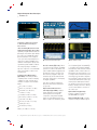
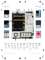
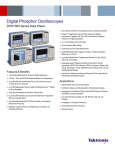
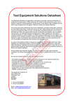
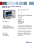
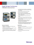
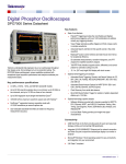
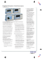
Digital Phosphor Oscilloscopes
DPO7000 Series
Features & Benefits
3.5 GHz Bandwidth Model for
Serial and Digital Applications
2.5 GHz, 1 GHz and 500 MHz
Bandwidth Models for All
Applications
Up to 40 GS/s Real-time Sample
Rate on One Channel and Up to
10 GS/s on All Four Channels
Up to 400 Megasamples Record
Length with MultiView Zoom™
Feature for Quick Navigation
>250,000 wfm/s Maximum
Waveform Capture Rate
MyScope® Custom Windows
Enhance Productivity
Right Mouse Click Menus
for Exceptional Efficiency
Unmatched Performance for Greater Insight Into Your Design
to Get Your Work Done Faster
The DPO7000 Series are the new
generation of real-time digital phosphor
oscilloscopes and are the industry’s
best solution to the challenging signal
integrity issues faced by designers
verifying, characterizing, debugging and
testing sophisticated electronic designs.
The family features exceptional performance in signal acquisition and analysis,
operational simplicity and unmatched
debugging tools to accelerate your
day-to-day tasks. The largest screen
in the industry and the intuitive user
interface provide easy access to the
maximum amount of information.
Unmatched Acquisition
Performance
Signal Fidelity of Tektronix
Oscilloscopes Ensures Confidence
in Your Measurement Results
High sample rate on all models, on all channels, to capture more signal details (transients, imperfections, fast edges)
– 40 GS/s on one channel on the 2.5 GHz
and 3.5 GHz models
– Option 2SR to double the maximum realtime sample rate for the 500 MHz and
1 GHz models
High bandwidth up to 3.5 GHz, matched
across 2, 3 or 4 channels and enabled by
Tektronix proprietary DSP enhancement. The
user-selectable DSP filter on each channel
provides magnitude and phase correction plus
extension to 3.5 GHz for more accurate signal
fidelity for complex measurements. The DSP
filter on each channel can also be switched
off to take advantage of true 2.5 GHz analog
bandwidth for applications needing the highest
available raw data capture
Very low jitter noise floor and vertical accuracy
for very accurate measurements
Longest acquisition of the industry to provide
more resolution and longer time sequence
– Standard 10 million data points per
channel on the DPO7000 Series
– Optional up to 400 million total data points
on 2.5 GHz and 3.5 GHz models
– Optional up to 200 million total data points
on the 500 MHz and 1 GHz models
Pinpoint™ Triggering Provides
the Most Flexible and Highest
Performance Triggering, with Over
1400 Combinations to Address
Virtually Any Triggering Situation
Small Footprint and Light Weight
12.1" Largest XGA Touch Screen
Display in the Industry
Communications Mask Testing
Clock Recovery from Serial
Data Streams
64 Bit NRZ Serial Pattern Trigger
for Isolation of Pattern-dependent
Effects Up to 1.25 Gb/s
Serial Pattern Triggering
Low-speed Serial Protocol
Triggering (I2C, SPI, RS-232, CAN)
Technology-specific Software
Solutions Provide Built-in Domain
Expertise for Ethernet, USB 2.0
Compliance Testing, Jitter and
Timing Measurements, Power
Measurements, CAN and LIN
Network Design
OpenChoice® Software with
Microsoft Windows XP OS
Enables Built-in Networking
and Extended Analysis
Applications
– Easily manage this deep record length, provide
detailed comparison and analysis of multiple
waveform segments with the MultiView Zoom™
feature. Automatically scroll through deep
records visually or create a math expression to instantly highlight differences
Signal Integrity, Jitter and Timing
Analysis
Highest performance probing solutions for
differential and single-ended voltage signals
as well as current measurement, because
accurate design verification depends on
high bandwidth access to critical signals
and high-fidelity signal capture
Low-speed Serial Bus Design
(I2C, SPI, CAN, LIN, RS-232)
Verification, Debug and Characterization of Sophisticated Designs
Debugging and Compliance Testing
of Serial Data Streams for Telecom
and Datacom Industry Standards
Investigation of Transient
Phenomena
Power Measurements and Analysis
Spectral Analysis
Digital Phosphor Oscilloscopes
DPO7000 Series
Zoom in on four areas of interest simultaneously to compare them.
Unmatched Versatility
With the MyScope® Feature, Create
Your Own Control Windows With
Only the Controls, Features and
Capabilities that You Care About
Easily create your own personalized
“toolbox” of oscilloscope features in a
matter of minutes using a simple, visual,
drag-and-drop process. Once created,
these custom control windows are easily
accessed through a dedicated MyScope
button and menu selection on the oscilloscope button/menu bar, just like any
other control window. You can make
an unlimited number of custom control
windows, enabling each person who uses
the oscilloscope in a shared environment
to have their own unique control window.
MyScope control windows will benefit all
oscilloscope users, eliminating the rampup time that many face when returning
to the lab after not using an oscilloscope
for a while, and enables the power user
to be far more efficient. Everything you
need is found in one control window
rather than having to constantly navigate
through menu after menu to repeat
similar tasks.
2
Tektronix Active probes achieve high-speed
signal acquisition and measurement fidelity.
Drag-and-drop menu items of interest
to create the MyScope control window.
With OpenChoice® Software,
Customize Your Test and
Measurement System with
Familiar Analysis Tools
The analysis and networking features of
OpenChoice software add flexibility to
Tektronix’ Windows XP oscilloscopes:
Using the fast embedded bus, waveform
data can be moved directly from acquisition
to analysis applications on the Windows
desktop at much faster speeds than
conventional GPIB transfers. Tektronix’
implementation of industry standard
protocols, such as TekVISA™ interface and
ActiveX controls, are included for using
and enhancing Windows applications for
data analysis and documentation. IVI-COM
instrument drivers are included to enable
easy communication with the oscilloscope
using GPIB, serial data and LAN connections from programs running on the
instrument or an external PC. Or, use the
Software Developer’s Kit (SDK) to help
create custom software to automate multistep processes in waveform collection
and analysis with Visual BASIC, C, C++,
MATLAB, LabVIEW, LabWindows/CVI
Digital Phosphor Oscilloscopes • www.tektronix.com/oscilloscopes
Capture data into Microsoft Excel using the
unique Excel toolbar, and create custom
reports using the Word toolbar.
and other common Application
Development Environments (ADE).
Integration of the oscilloscope with
external PCs and non-Windows hosts
is also supported by the DPO7000
Series software solutions. In addition,
the OpenChoice architecture provides
a comprehensive software infrastructure
for faster, more versatile operations. Data
transfer programs, such as the Excel or
Word toolbar, are used to simplify analysis
and documentation on the Windows
desktop or on an external PC.
Digital Phosphor Oscilloscopes
DPO7000 Series
Maximize the probability of capturing elusive
glitches and other infrequent events with
FastAcq acquisition mode.
Accelerate the Debug of
Complex Electrical Designs
FastAcq Acquisition Mode
Expedites Debugging by Clearly
Showing Imperfections
More than just color-grading, FastAcq
enabled by Tektronix proprietary DPX®
acquisition technology, captures signals
up to more than 250,000 waveforms per
second on all 4 channels simultaneously,
dramatically increasing the probability of
discovering infrequent fault events. And
with a simple turn of the intensity knob
you can clearly see “a world others don’t
see,” because frequency of occurrence is
color-coded. Some oscilloscope vendors
claim high waveform capture rates for
short bursts of time, but only the DPO7000
Series, enabled by DPX technology, can
deliver these fast waveform capture rates
on a sustained basis – saving minutes,
hours or even days by quickly revealing the
nature of faults so sophisticated trigger
modes can be applied to isolate them.
Isolate glitches down to 200 ps wide.
The Ability to Trigger an
Oscilloscope on Events of Interest
is Paramount in Complex Signal
Debug and Validation
Whether you’re trying to find a system
error or need to isolate a section of a
complex signal for further analysis,
Tektronix’ Pinpoint™ triggering provides
the solution. The Pinpoint trigger system
uses Silicon Germanium (SiGe) technology to provide trigger sensitivity of
up to the bandwidth of the instrument,
and allows selection of most trigger types
on both A and B trigger circuits. It can
capture very narrow glitches with very little
trigger jitter. Other trigger systems offer
multiple trigger types only on a single
event (A event), with delayed trigger (B
event) selection limited to edge type triggering and often do not provide a way to
reset the trigger sequence if the B event
doesn’t occur. But Pinpoint triggering
provides a full suite of advance trigger
types on both A and B triggers with
Reset triggering to begin the trigger
sequence again after a specified time,
state or transition so that even events
in the most complex signals can be
captured. Other oscilloscopes typically
Isolate set-up and hold violations down to
360 ps.
offer less than 20 trigger combinations;
Pinpoint triggering offers over 1400
combinations, all at full performance.
Now you can even use a probe and the
full functionality of the trigger system
with the Auxiliary trigger input.
Trigger on the Most Relevant
Bit Sequence of the Industry
Standard Serial Bus
I2C (Inter-Integrated Circuit) triggering is
a standard feature and includes Start
condition, Missing Acknowledge, Restart,
Data Read, Address and/or Data Frame,
in a 10 bit or 7 bit format.
SPI (Serial Peripheral Interface) triggering
is a standard feature and includes triggering on a data pattern within a userdefinable frame.
RS-232 triggering is a standard feature.
CAN (Controller Area Network) triggering
is an optional feature (Opt. LSA) and
includes synchronization to the Start or
End of a CAN frame on any CAN high
or CAN low signal, triggering on Type of
Frame (Data, Remote, Overload), Identifier,
Data, Missing Acknowledge and Bit
Stuffing error.
Digital Phosphor Oscilloscopes • www.tektronix.com/oscilloscopes
3
Digital Phosphor Oscilloscopes
DPO7000 Series
Easily trigger on a specific I2C address.
Triggering on an analog HDTV tri-level sync
signal and examining horizontal blanking
interval.
Analog HDTV/EDTV triggering for
emerging standards like 1080i, 1080p,
720p and 480p as well as standard video
triggering on any line within a field, all lines,
all fields, odd or even fields for NTSC,
SECAM and PAL video signals. In addition,
IRE and mV graticules can be selected
for easier measurements and visual
inspection. This is a standard feature.
Large 12.1-inch XGA Display Screen
To debug serial architectures, use the
serial pattern triggering option for NRZ
serial data stream with built-in clock
recovery (available on models DPO7254
and DPO7354 only). The instrument
can recover the clock signal, identify the
transitions and decode characters and
other protocol data. With the combination
of the Serial Trigger and Protocol Decode
software, you can see the captured bit
sequences decoded into their words for
convenient analysis (for 8b/10b and other
encoded serial data streams), or you can
set the desired encoded words for the
serial pattern trigger to capture. This serial
trigger option covers NRZ serial standards
up to 1.25 Gb/s.
Unmatched Usability
4
The DPO7000 Series has the largest
display in the industry with a 12.1-inch
XGA touch screen that gives up to 15%
more waveform display than other
oscilloscope series in its class.
Ten vertical divisions give you 25%
more vertical measurement resolution.
The TekVPI™ probe interface provides
versatility and ease of use enabled by
intelligent bi-directional oscilloscope-toprobe communication.
The DPO7000 Series are fast-responding
instruments and contain a comprehensive
suite of features, such as a touch-screen,
shallow menu structures, intuitive graphical icons, knob-per-channel vertical
controls, support for right mouse clicks,
mouse wheel improvements, saving of
waveforms and measurements available
in Preview mode, Export/Save/Recall
menu improvements.
Digital Phosphor Oscilloscopes • www.tektronix.com/oscilloscopes
Serial pattern triggering to debug pattern
dependent issues.
Interoperability with Logic Analyzers
for Digital Design and Debug
Tektronix’ Integrated View (iView™) data
display enables digital designers to solve
signal integrity challenges and effectively
debug and verify their systems more
quickly and easily. This integration allows
designers to view time-correlated digital
and analog data in the same display
window, and isolate the analog characteristics of the digital signals that are
causing systems failures. No user calibration is required. And, once set up, the
iView feature is completely automated.
Digital Phosphor Oscilloscopes
DPO7000 Series
How does 12.1-inch display compare to the display size of other
oscilloscopes?
More Insight into Your
Complex Electrical Design
for Characterization and
Compliance Testing
Whether it’s a simple math expression,
waveform mask testing, a pass/fail
compliance test or a custom application
that you develop, the DPO7000 Series
Oscilloscopes offer the industry’s most
comprehensive set of analysis and
compliance tools.
A Wide Range of Built-in Advanced
Waveform Analysis Tools
Waveform cursors make it easy to
measure trace-to-trace timing characteristics, while cursors that link between
YT and XY display modes make it easy
to investigate phase relationships and
Safe Operating Area violations. Select
from 53 automatic measurements using
a graphical palette that logically organizes measurements into Amplitude,
Time, Combination, Histogram and
Communications categories. Gather
further insight into your measurement
results with statistical data such as
mean, min, max, standard deviation
and population.
An integrated toolset for digital design and troubleshooting.
Define and apply math expressions to
waveform data for on-screen results in
terms that you can use. Access common
waveform math functions with the touch
of a button. Or, for advanced applications,
create algebraic expressions consisting
of live waveforms, reference waveforms,
math functions, measurement values,
scalars and user-adjustable variables with
an easy-to-use, calculator-style editor.
Basic spectral UI control window.
FFT – To analyze your signal in the
spectral domain, use the basic spectral
(provides you with the best parameter),
or use the advanced spectral (to directly
control the frequency span, center
frequency and resolution bandwidth).
Filtering – Enhance your ability to isolate
or remove some important component
of your signal (noise or specific harmonics
of the signal) by creating your own filters,
or using the filters provided as standard
with the instrument.
Digital Phosphor Oscilloscopes • www.tektronix.com/oscilloscopes
5
Digital Phosphor Oscilloscopes
DPO7000 Series
Jitter and Timing measurement.
CAN and LIN Timing and Protocol Decode.
Ethernet compliance testing.
Power measurement and analysis.
USB compliance testing.
A Breadth of Optional Packages
to Extend Waveform Analysis
Even Further
Jitter and Timing Measurement and
Analysis Package (Opt. JA3 or JE3) –
Tight timing margins demand stable, low
jitter designs. This software option extends
the oscilloscope capability by making
jitter measurements over contiguous
clock cycles from every valid pulse in a
single-shot acquisition. Multiple measurements and trend plots quickly show
system timing under variable conditions.
This analysis package is available as
Opt. JA3 or Opt. JE3 on the DPO7000
Series. JE3 provides a subset of the
measurements.
Communications Mask Testing
(Opt. MTM) – This feature provides a
complete portfolio of masks for verifying
compliance to serial communications
standards. It supports 156 Standards
Masks –
ITU-T (64 Kb/s to 155 Mb/s)
ANSI T1.102 (1.544 Mb/s to 155 Mb/s)
Ethernet IEEE 902.3, ANSI X3.263
(125 Mb/s to 1.25 Gb/s)
Sonet/SDH (51.84 Mb/s to 622 Mb/s)
Fibre Channel (133 Mb/s to 2.125 Gb/s)
USB (12 Mb/s to 480 Mb/s)
CAN and LIN Timing and Protocol
Decode Software (Opt. LSA) – When
you need to ensure seamless and reliable
operation of a CAN or LIN network, this
option enables CAN bus triggering and
provides the solution to measure oscillator tolerance, propagation delay and
simultaneously decode CAN and LIN
messages, with the protocol leveraging
the trigger capabilities.
This option is offered on DPO7354,
DPO7254, DPO7104 and DPO7054
as Opt. LSA.
Optional Power Measurement
and Analysis (Opt. PWR) – Analyze
power dissipation in power supply
switching devices and magnetic
components, and generate detailed
reports in customizable formats. The
HiRes acquisition mode delivers greater
IEEE 1394 (491.5 Mb/s to 1.966 Gb/s)
RapidI/O (up to 2 Gb/s)
OIF Standards (1.244 Gb/s)
Video (143.18 Mb/s to 1.485 Gb/s)
6
Digital Phosphor Oscilloscopes • www.tektronix.com/oscilloscopes
than 8 bits of vertical resolution on singleshot or repetitive signals at bandwidth up
to 125 MHz. The powerful and flexible
measurements, math and math-on-math
capabilities make it an ideal solution for
performing power measurements, such
as voltage, current, instantaneous power
and energy, for power device designers.
The new TekVPI™ interface provides smart
communication between the oscilloscope
and the probe. TekVPI probe interface
also provides more power to the probe
interface, allowing customers to directly
connect current probes to the front of
the oscilloscope.
Optional Ethernet (Opt. ET3) –
Provides compliance testing for
10/100/1000Base-T signals.
Optional USB (Opt. USB) – Provides
compliance testing for USB2.0 signals.
Digital Phosphor Oscilloscopes
DPO7000 Series
Characteristics
Vertical System
DPO7054
DPO7104
N/A
N/A
Input Channels
Bandwidth (DSP Bandwidth
Enhance)
Rise Time (DSP Bandwidth
Enhance)
Hardware Analog
Bandwidth (–3 dB)
Rise Time 10% to 90% (typical)
Rise Time 20% to 80% (typical)
DPO7254
DPO7354
N/A
3.5 GHz*1
4
115 ps
500 MHz
1 GHz
2.5 GHz
2.5 GHz
460 ps
310 ps
300 ps
200 ps
160 ps
100 ps
145 ps
95 ps
DC Gain Accuracy
Hardware Bandwidth Limits
Input Coupling
Input Impedance (software
selectable)
Input Sensitivity
Vertical Resolution
±1% with offset/position set to 0
250 MHz or 20 MHz
AC, DC, GND
1 MΩ ±1% with 13 pF ±2 pF or
50 Ω ± 1%
1 MΩ: 1 mV/div to 10 V/div
50 Ω: 1 mV/div to 1 V/div
8 bit (>11 bit with averaging)
Max Input Voltage, 1 MΩ
±150 V CAT I, derate at 20 dB/decade to 9 VRMS above 200 kHz
Max Input Voltage, 50 Ω
5 VRMS, with peaks less than ±24 V
Position Range
Offset Range
Offset Accuracy
Delay between any two
channels (typical)
Channel-to-Channel Isolation
(any two channels at equal
vertical scale settings) (typical)
*1
±5 divisions
1 mV/div to 50 mV/div: ±1 V
50.5 mV/div to 99.5 mV/div: ±0.5 V
100 mV/div to 500 mV/div: ±10 V
505 mV/div to 995 mV/div: ±5 V
1 V/div to 5 V/div: ±100 V
5.05 V/div to 10 V/div: ±50 V
1 mV/div to 9.95 mV/div: ±0.2% (offset value-position) ±0.1 div ±1.5 mV
10 mV/div to 99.5 mV/div: ±0.35% (offset value-position) ±0.1 div ±1.5 mV
100 mV/div to 1 V/div: ±0.35% (offset value-position) ±0.1 div ±15 mV
1.01 V/div to 10 V/div: ±0.25% (offset value-position) ±0.1 div ±150 mV
≤100 ps (50 Ω, DC coupling and equal V/div at or above 10 mV/div)
≥100:1 at ≤100 MHz;
≥30:1 between 100 MHz and 2.5 GHz
> 20:1 between 2.5 and 3.5 GHz
3 GHz for sinewave of more than 4 div amplitude (typically).
Digital Phosphor Oscilloscopes • www.tektronix.com/oscilloscopes
7
Digital Phosphor Oscilloscopes
Digital Phosphor Oscilloscopes
DPO7000 Series
DPO7000 Series
9
5
9
12
4
7
6
10
Power measurement.
Basic spectral UI control window.
11
1
5
Testing a 622 Mb/s signal against the mask
specified by the standard.
Jitter and Timing Measurement.
3
8
USB compliance testing.
CAN and LIN Timing and Protocol Decode.
11
1 Large 12.1-inch
XGA Touch Screen
Display
The DPO7000 series
touch screen gives
up to 15% more
waveform display than
other oscilloscopes
of its class.
8
2 New Probe
Interface
TekVPI™ probe interface
provides versatility and
ease of use enabled by
intelligent bi-directional
oscilloscope-to-probe
communication.
3 Exceptional
Performance
The performance of
the highest bandwidth
oscilloscope in a midrange offering with up
to 40 GS/s real-time
sample rate and 400 M
record length on
one channel.
4 With MultiView
Zoom™
Easily deep into very
long record of acquired
data, analyze multiple
waveform segments
simultaneously and
scroll automatically
through the deepest
records visually.
Digital Phosphor Oscilloscopes • www.tektronix.com/oscilloscopes
2
5 Unmatched
Usability
With MyScope®, create
your own control
window with only
the controls you care
about. The versatile
user interface allows
you to use the touch
screen or the mouse.
6 Accelerate the
Debug of Complex
Designs with
Pinpoint™
Triggering
Access up to 1400
trigger combinations
to address virtually
any triggering
situations.
7 FastAcq Acquisition Expedites
Debugging by
Clearly Showing
Faults
More than 250,000
waveforms per second,
and with a simple turn
of the intensity knob,
clearly see the frequency of occurrence.
8 Easy Connectivity
Built-in USB port at
the front, to ease the
saving of your work.
Most standard
input/output ports
available on the side
of the instrument.
9 A Wide Range of
Built-in Advanced
Analysis Tools
Cursors that link
between XY and YT.
53 automatic
measurements.
Many math functions,
common and more
advanced (like FFT
and Spectral).
10 For Insight into
Your Low-speed
Serial Designs
Serial Protocol
Triggering for I2C, SPI,
CAN plus a complete
CAN and LIN timing
and protocol analysis
software package.
11 For Insight into
Your High-speed
Serial Designs
Optional NRZ Serial
Pattern triggering plus
Recovered Clock and
Recovered Data available on the front of
the DPO7254 or the
DPO7354 instruments.
12 A Breadth of
Optional Software
Packages for
Expanded Waveform Analysis
Digital Phosphor Oscilloscopes • www.tektronix.com/oscilloscopes
9
Digital Phosphor Oscilloscopes
DPO7000 Series
Time Base System
DPO7054
DPO7104
DPO7254 / DPO7354
25 ps/div to 1000 s/div
Time Base Range
100 ps/div to 1000 s/div
50 ps/div to 1000 s/div
with Opt. 2SR
50 ps/div to 1000 s/div
25 ps/div to 1000 s/div
—
1 ps
500 fs
250 fs
250 fs
—
Time Resolution (in ET/IT mode)
with Opt. 2SR
500 fs
Time Base Delay Time Range
5 ns to 250 s
Channel-to-Channel Deskew
Range ±75 ns
Delta Time Measurement Accuracy
((0.06/sample rate) + (2.5 ppm x Reading)) RMS
Trigger Jitter (RMS)
1.5 ps RMS (typical)
<1 ps RMS (<2 ps peak) for record duration <10 µs (typical)
<2.5 psRMS for record duration <30 ms
<65 parts/trillion for record durations <10 s
Jitter Noise Floor
Time Base Accuracy
±2.5 ppm + Aging <1 ppm per year
Acquisition System
DPO7054
DPO7104
DPO7254/DPO7354
1 Channel (max)
10 GS/s
20 GS/s
40 GS/s
With Opt. 2SR
20 GS/s
40 GS/s
—
2 Channels (max)
5 GS/s
10 GS/s
20 GS/s
With Opt. 2SR
10 GS/s
20 GS/s
—
3 to 4 Channels (max)
2.5 GS/s
5 GS/s
10 GS/s
10 GS/s
—
Real-time Sample Rates
With Opt. 2SR
5 GS/s
Equivalent Time Sample Rate (max)
4 TS/s (for repetitive signals)
Maximum Record Length per Channel
With Standard Configuration
40 M (1-CH.), 20 M (2-CH.), 10 M (4-CH.)
With Record Length Opt. 2RL
80 M (1-CH.), 40 M (2-CH.), 20 M (4-CH.)
With Record Length Opt. 5RL
With Record Length Opt. 10RL
200 M (1-CH.), 100 M (2-CH.), 50 M (4-CH.)
—
—
400 M (1-CH.)
200 M (2-CH.)
100 M (4-CH.)
Maximum Duration at Highest Real-time Resolution (1-CH)
DPO7054
DPO7104
DPO7254 / DPO7354
Resolution
100 ps (10 GS/s)
50 ps (20 GS/s)
25 ps (40 GS/s)
With Opt. 2SR
50 ps (20 GS/s)
25 ps (40 GS/s)
—
Max Duration with Standard Record
Length and Sample Rate
4 ms
2 ms
1 ms
With Opt. 2SR
2 ms
1 ms
—
2 ms
Max Duration with Opt. 2RL
8 ms
4 ms
With Opt. 2SR
4 ms
2 ms
—
Max Duration with Opt. 5RL
20 ms
10 ms
5 ms
With Opt. 2SR
10 ms
5 ms
—
—
—
10 ms
Max Duration with Opt. 10RL
10
Digital Phosphor Oscilloscopes • www.tektronix.com/oscilloscopes
Digital Phosphor Oscilloscopes
DPO7000 Series
Acquisition Modes
DPO7054/DPO7104/DPO7254/DPO7354
FastAcq Acquisition Mode
Maximum FastAcq Waveform Capture Rate
Waveform Database
Sample
Peak Detect
FastAcq optimizes the instrument for analysis of dynamic signals and capture of infrequent events
>250,000 wfm/s on all 4 channels simultaneously
Accumulate waveform database providing three-dimensional array of amplitude, time and counts
Acquire sampled values
Captures narrow glitches at all real-time sampling rates: 1 ns at ≤125 MS/s; 1/sample rate at ≥250 MS/s
Averaging
From 2 to 10,000 waveforms included in average
Envelope
From 1 to 2 x 10⁹ waveforms included in min-max envelope
Hi-Res
FastFrame™ Acquisition
Roll Mode
Real-time boxcar averaging reduces random noise and increases resolution
Acquisition memory divided into segments; maximum trigger rate >310,000 waveforms per second.
Time of arrival recorded with each event
Up to 10 MS/s with a maximum record length of 40 M
Pinpoint ™ Trigger System
DPO7054/DPO7104/DPO7254/DPO7354
Sensitivity
Internal DC Coupled
External (auxiliary input) 1 MΩ
0.7 div DC to 50 MHz increasing to 1.2 div at rated analog bandwidth (typical); 2.5 div at 3.5 GHz with DSP Bandwidth enhance
250 mV from DC to 50 MHz increasing to 350 mV at 250 MHz (typical)
Trigger Characteristics
A Event and Delayed B Event Trigger Types
Low Speed Serial Protocol Trigger Type (A Event only)
Edge, Glitch, Runt, Width, Transition Time, Timeout, Pattern, State, Setup/Hold, Window – all except Edge, Pattern and State
can be Logic State qualified by up to two channels
I 2C, SPI and RS-232 (standard). CANbus available as Opt. LSA. Trigger on address, data and special handshaking states
and other conditions
Main Trigger Modes
Auto, Normal and Single
Trigger Sequences
Main, Delayed by Time, Delayed by Events, Reset by Time, Reset by State, Reset by Transition. All sequences can include
separate horizontal delay after the trigger event to position the acquisition window in time
Communications-related Triggers
Serial Pattern Trigger
Video Type Trigger Formats and Field Rates
Clock Recovery System
Clock Recovery Phase Locked Loop Bandwidth
Frequency Range
Clock Recovery Jitter (RMS)
Tracking/Acquisition Range
Minimum Signal Amplitude needed for Clock Recovery
Requires Opt. MTM. Support for AMI, HDB3, BnZS, CMI, MLT3 and NRZ encoded communications signals.
Select among isolated positive or negative one, zero pulse form or eye patterns as applicable to the standard
On DPO7254 or DPO7354 only, and requires Opt. PTM. Up to 64 bit serial word recognizer, bits specified in binary
(high, low, don’t care) or hex format. Trigger on NRZ-encoded data up to 1.25 Gb/s
Triggers from negative sync composite video, field 1 or field 2 for interlaced systems, any field, specific line, or any line
for interlaced or non-interlaced systems. Supported systems include NTSC, PAL, SECAM and HDTV 1080/24sF,
1080p/25, 1080i/50, 1080i/60, 1080p/24, 720p/60, 480p/60
On DPO7254 or DPO7354 only and requires Opt. PTM or MTM
Fixed at FBaud/500
1.5 MBaud to 1.25 GBaud
<0.25% bit period + 5 psRMS for PRBS data patterns
<0.25% bit period + 5 psRMS for repeating “0011” data pattern (typical)
±5% of requested baud (typical)
1 divpk-pk up to 1.25 GBaud (typical)
Trigger Level Range
Internal
AUX Trigger
Line
Trigger Coupling
Trigger Holdoff Range
±12 divisions from center of screen
TekVPI interface; ±5 V (50 Ω); 150 V CAT I, derate at 20 dB/decade to 9 V RMS above 200 KHz (1 MΩ)
Fixed at 0 V
DC, AC (attenuates <60 Hz), HF Rej (attenuates >30 kHz), LF Rej (attenuates <80 kHz), Noise Reject (reduces sensitivity)
250 ns min to 12 s max
Digital Phosphor Oscilloscopes • www.tektronix.com/oscilloscopes
11
Digital Phosphor Oscilloscopes
DPO7000 Series
Trigger Modes
Waveform Measurements
Edge – Positive or negative slope on any channel or
front panel auxiliary input. Coupling includes DC, AC,
noise reject, HF reject and LF reject.
Glitch – Trigger on or reject glitches of positive,
negative or either polarity. Minimum glitch width is
down to 170 ps (typical) with re-arm time of 250 ps
(for DPO7254 or DPO7354).
Width – Trigger on width of positive or negative
pulse either within or out of selectable time limits
(down to 225 ps).
Runt – Trigger on a pulse that crosses one
threshold but fails to cross a second threshold
before crossing the first again. Event can be timeor logic-qualified.
Timeout – Trigger on an event which remains high,
low or either, for a specified time period. Selectable
from 300 ps.
Transition – Trigger on pulse edge rates that are
faster or slower than specified. Slope may be positive, negative or either.
Setup/Hold – Trigger on violations of both setup
time and hold time between clock and data present
on any two input channels.
Pattern – Trigger when pattern goes false or stays
true for specified period of time. Pattern (AND, OR,
NAND, NOR) specified for four input channels
defined as high, low or don’t care.
State – Any logical pattern of channels (1, 2, 3)
clocked by edge on channel 4. Trigger on rising or
falling clock edge.
Window – Trigger on an event that enters or exits a
window defined by two user-adjustable thresholds.
Event can be time- or logic-qualified.
Trigger Delay by Time – 5 ns to 250 s.
Trigger Delay by Events – 1 to 10,000,000 events.
Comm – Provided as part of Opt. MTM. Support for
AMI, HDB3, BnZS, CMI, MLT3 and NRZ encoded
signals.
I2C, SPI and RS-232 – Protocol trigger on
DP07054, DPO7154, DPO7254 or DPO7354.
CAN – Protocol trigger on DP07054, DPO7154,
DPO7254 or DPO7354 as part of Opt. LSA.
Serial Pattern – Captures serial data stream with
built-in clock recovery for NRZ standards up to
1.25 Gb/s. Opt. ST.
Automatic Measurements – 53, of which 8 can be
displayed on screen at any one time; measurement
statistics, user-definable reference levels, measurement within gates isolating the specific occurrence
within an acquisition to take measurements on.
Amplitude Related – Amplitude, High, Low,
Maximum, Minimum, Peak-to-Peak, Mean, Cycle
Mean, RMS, Cycle RMS, Positive Overshoot,
Negative Overshoot.
Time Related – Rise Time, Fall Time, Positive Width,
Negative Width, Positive Duty Cycle, Negative Duty
Cycle, Period, Frequency, Delay.
Combination – Area, Cycle Area, Phase, Burst
Width.
Histogram Related – Waveform Count, Hits in Box,
Peak Hits, Median, Maximum, Minimum, Peak to
Peak, Mean (µ), Standard Deviation (σ), µ+1σ,
µ+2σ, µ+3σ.
Eye Pattern Related – Extinction Ratio (absolute,
%, dB), Eye Height, Eye Width, Eye Top, Eye Base,
Crossing %, Jitter (pk-pk, RMS, 6σ), Noise (pk-pk,
RMS), Signal/Noise Ratio, Cycle Distortion, Q-Factor.
12
Waveform Processing/Math
Arithmetic – Add, Subtract, Multiply, Divide
Waveforms and Scalars.
Algebraic Expressions – Define extensive algebraic
expressions including Waveforms, Scalars, Useradjustable Variables and Results of Parametric
Measurements, e.g., (Integral (CH.1–Mean(CH.1)) x
1.414 x VAR1).
Math Functions – Average, Invert, Integrate,
Differentiate, Square Root, Exponential, Log10, Loge,
Abs, Ceiling, Floor, Min, Max, Sin, Cos, Tan, ASin,
ACos, ATan, Sinh, Cosh, Tanh.
Relational –
Boolean result of comparison >, <, ≥, ≤, =, ≠.
Frequency Domain Functions – Spectral
Magnitude and Phase, Real and Imaginary Spectra.
Vertical Units –
Magnitude: Linear, dB, dBm.
Phase: Degrees, radians, group delay.
IRE and mV units.
Window Functions – Rectangular, Hamming,
Hanning, Kaiser-Bessel, Blackman-Harris, Gaussian,
Flattop2, Tek Exponential.
Waveform Definition – As an arbitrary math
expression.
Digital Phosphor Oscilloscopes • www.tektronix.com/oscilloscopes
Filtering Functions – User-definable filters. Users
specify a filter containing the coefficients of the filter.
Filter files provided.
Mask Function – A function that generates a
Waveform Database pixmap from a sample waveform. Sample count can be defined.
Display Characteristics
Display Type – Liquid crystal active-matrix color
display.
Display Size – Diagonal: 307.3 mm (12.1 in.).
Display Resolution – XGA 1240 horizontal x 768
vertical pixels.
Waveform Styles – Vectors, Dots, Variable
Persistence, Infinite Persistence.
Color Palettes – Normal, Green, Gray, Temperature,
Spectral and User-defined.
Display Format – YT, XY
Computer System and
Peripherals
Operating System – Windows XP.
CPU – Intel Pentium 4, 3.4 GHz processor.
PC System Memory – 2 GB.
Hard Disk Drive – Rear-panel, removable hard disk
drive, 80 GB capacity.
CD-R/W Drive – Front-panel CD-R/W drive with CD
creation software application.
DVD Drive – Read only.
Mouse – Optical wheel mouse, USB interface.
Printer (optional) – Thermal printer; fits in accessories pouch provided with instrument.
Keyboard – Order 119-7083-00 for small keyboard
(fits in pouch); USB interface and hub.
Input/Output Ports
Front Panel
Probe Compensator Output – Front panel pins.
Amplitude 1 V ±20% into a ≥50 Ω load; 500 mV
from base to top into a 50 Ω load, frequency 1 kHz
±5%.
Recovered Clock (for DPO7254 or DPO7354 only) –
BNC connector, ≤1.25 Gb/s, Output swing≥130 mVpk-pk
into 50 Ω. Requires option to enable.
Recovered Data (for DPO7254 or DPO7354 only) –
BNC connector , ≤1.25 Gb/s, Output swing 200 mV
into 50 Ω. Requires option to enable.
USB 2.0 Port – One USB 2.0 connector.
Aux Trigger Input – See Trigger specification.
Digital Phosphor Oscilloscopes
DPO7000 Series
Side Panel
Physical Characteristics
Parallel Port – IEEE 1284, DB-25 connector.
Audio Ports – Miniature phone jacks (disabled).
Keyboard Port – PS-2 compatible.
Mouse Port – PS-2 compatible.
USB Ports – Four USB 2.0 connectors.
LAN Port –
RJ-45 connector, supports 10Base-T, 100Base-T
and Gigabit Ethernet.
Serial Port – DB-9 COM1 port.
VGA Video Port –
DB-15 female connector; connect a second monitor
to use dual-monitor display mode. Supports basic
requirements of PC99 specifications.
Oscilloscope VGA Video Port –
DB-15 female connector, 31.6 kHz sync, EIA RS343A compliant, connect to show the oscilloscope
display, including live waveforms on an external
monitor or projector.
Benchtop Configuration
Dimensions
mm
Height
292
Width
451
Depth
265
Weight
kg
Net
15
Shipping
28.9
Rackmount Configuration
Dimensions
mm
Height
323
Width
479
Depth (from rack231.75
mounting ear to
back of instrument)
Weight
kg
Net
17.4
Rackmount Kit
2.5
Rear Panel
Power –
100 to 240 VRMS ± 10%, 47 to 63 Hz, <550 W
115 VRMS ± 10%, 400 Hz, CAT I, <500 VA.
Analog Signal Output –
BNC connector provides a buffered version of the
signal that is attached to the Ch 3 input
Amplitude: 50 mV/div ±20% into a 1 MΩ load,
25 mV/div ±20% into a 50 Ω load
Bandwidth: 100 MHz into a 50 Ω load
Software-Switchable BNC Connector –
External Time Base Reference In: BNC connector,
time base system can phase-lock to external
10 MHz reference.
Time Base Reference Out: BNC connector, provides
TTL-compatible output of internal 10 MHz reference
oscillator.
Aux Trigger Output –
BNC connector provides a TTL-compatible, polarity
switchable pulse when the oscilloscope triggers.
GPIB Port – IEEE 488.2 standard.
Humidity
in.
11.48
17.75
10.44
lbs.
32
63.75
in.
12.25
18.85
9.12
Altitude
Operating – 10,000 ft. (3,048 m).
Non-operating – 40,000 ft. (12,190 m).
Random Vibration
lbs.
37.5
5.5
Mechanical
Cooling — Required Clearance
mm
Top
0
Bottom
0
Left side
76
Right Side
0
Front
0
Rear
0
Operating –
5% to 95% relative humidity (RH) with a maximum
wet bulb temperature of +29 ºC at or below +50 ºC,
non-condensing. Upper limit derated to 45% RH
above +30 ºC up to +50 ºC.
Non-operating –
5% to 95% relative humidity (RH) with a maximum
wet bulb temperature of +29 ºC at or below +60 ºC,
non-condensing. Upper limit derated to 45% RH
above +30 ºC up to +50 ºC.
in.
0
0
3
0
0
0
Operating –
0.000125 G2/Hz from 5 to 350 Hz, –3 dB/octave
from 350 to 500 Hz, 0.0000876 G2/Hz at 500 Hz.
Overall level of 0.27 GRMS.
Non-operating –
0.0175 G2/Hz from 5 to 100 Hz, –3 dB/octave from
100 to 200 Hz, 0.00875 G2/Hz from 200 to 350 Hz,
–3 dB/octave from 350 to 500 Hz, 0.006132 G2/Hz
at 500 Hz. Overall level of 2.28 GRMS.
Regulatory
Electromagnetic Compatibility –
93/68/EEC; EN61326:1997 +A1 1998+A2:2000.
Certifications –
UL 3111-1, CSA1010.1, ISO11469, EN61010-1,
IEC 61010-1.
Environmental
Temperature
Operating –
0 ºC to +50 ºC, excluding CD-R/W drive;
+10 ºC to +45 ºC, including CD-R/W drive.
Non-operating – –40 ºC to +71 ºC.
Digital Phosphor Oscilloscopes • www.tektronix.com/oscilloscopes
13
Digital Phosphor Oscilloscopes
DPO7000 Series
Ordering Information
DPO7054
500 MHz Digital Phosphor Oscilloscope.
DPO7104
1 GHz Digital Phosphor Oscilloscope.
DPO7254
2.5 GHz Digital Phosphor Oscilloscope.
DPO7354
3.5 GHz Digital Phosphor Oscilloscope
for Serial and Digital applications.
All Models Include: Accessory pouch, front cover,
mouse, quick start user manual (071-173x-xx),
probe calibration and deskew fixture (067-0405-xx),
DPO7000 Series product software media, DPO7000
Series operating system restoration media, optional
applications software media, performance verification
procedure PDF file, GPIB programmer’s reference
(on product software media), calibration certificate
documenting NIST traceability, Z 540-1 compliance
and ISO9001, power cord, one year warranty. User
to specify quick start user manual language, and
power plug when ordering. DPO7054 also includes:
(4) P6139A 500 MHz, 10x passive probes. (Probes
and accessories are not included in the oscilloscope
warranty. Refer to the data sheet for each probe
for its unique warranty and calibration terms.)
Options
Instrument Options
Record Length Options
Opt. 2RL
80 MSamples max, 20 MSamples/ch
Opt. 5RL
200 MSamples max, 50 MSamples/ch
Opt. 10RL (for DPO7254/DPO7354 only)*2
400 MSamples max, 100 MSamples/ch
Hardware Options
Opt. 2SR*3 – Double maximum real-time sample rate
DPO7104: 40 GS/s (1 channel), 20 GS/s (2 channels), 10 GS/s (3 or 4 channels)
DPO7054: 20 GS/s (1 channel), 10 GS/s (2 channels), 5 GS/s (3 or 4 channels)
Opt. 1P – Thermal printer in the pouch.
Available for DPO7104/DPO7054 only
Printer option is available for all models
Software Options
Opt. LSA
Low Speed Serial Analysis includes CAN/LIN Trigger, Decode and Analysis
Opt. MTM
Mask Testing for Serial Communication Standards (up to 1.5 Gb/s).
Includes hardware clock recovery on DPO7254/DPO7354
Opt. PTM (for DPO7254/DPO7354 only)*2
8b/10b protocol triggering and NRZ serial pattern triggering.
Includes hardware clock recovery up to 1.5 Gb/s
Opt. JA3
TDSJIT3 Advanced Jitter Analysis Software
Opt. JE3
TDSJIT3 Essentials Jitter Analysis Software
Opt. ET3*4
TDSET3 Ethernet Compliance Test Software
Opt. USB*5
TDSUSBS USB2.0 Compliance Test Software only
Opt. PWR
DPOPWR Power Measurement and Analysis Software
Opt. RTE (for DPO7254/7354
Opt. DVI (for DPO7354
only)*6
only)*2
RT-Eye® Serial data compliance and analysis software
Digital Visual Interface compliance test software
Bundle Options
Opt. PS1
14
Power Bundle option includes TPA, BNC adapter, Probe Calibration and
deskew fixture 067-1686-xx, P5205, TCP0030 and Opt. PWR
Digital Phosphor Oscilloscopes • www.tektronix.com/oscilloscopes
Digital Phosphor Oscilloscopes
DPO7000 Series
User Manual Options
Opt. L0 – English manual.
Opt. L1 – French manual.
Opt. L3 – German manual.
Opt. L5 – Japanese manual.
Opt. L7 – Simplified Chinese manual.
Opt. L8 – Standard Chinese manual.
Opt. L9 – Korean manual.
Opt. L10 – Russian manual.
Power Plug Options
Opt. A0 – North America.
Opt. A1 – Universal European Union.
Opt. A2 – UK.
Opt. A3 – Australia.
Opt. A5 – Switzerland.
Opt. A6 – Japan.
Opt. A10 – China.
Opt. A11 – India.
Opt. A99 – No power cord.
Service Options
(Probes and accessories are not included in the
oscilloscope warranty. Refer to the data sheet for each
probe for its unique warranty and calibration terms.)
Opt. C3 – Calibration Service 3 years.
Opt. C5 – Calibration Service 5 years.
Opt. D1 – Calibration Data Report.
Opt. D3 – Calibration Data Report 3 years (with
Opt. C3).
Opt. D5 – Calibration Data Report 5 years (with
Opt. C5).
Opt. R3 – Repair Service 3 years.
Opt. R5 – Repair Service 5 years.
TPA-BNC – TekProbe-BNC Level 2 to TekVPI
adapter.
P6139A – 500 MHz, passive probe.
P6158 – 3 GHz, 20x low C probe.
P6247*7 – 1 GHz differential probe.
P6243*7 – 1 GHz active probe.
P6245*7 – 1.5 GHz active probe.
P6248*7 – 1.5 GHz differential probe.
P6330*7 – 3 GHz differential probe.
P6246*7 – 400 MHz differential probe.
P6101B – 1x passive probe 15 MHz.
TCPA300/TCPA400*7 – Series current measurement systems.
P5200/P5205/P5210*7 – High voltage differential
probes.
P5100/P6015A – High voltage probes.
Cables
GPIB Cable (1 m) – Order 012-0991-01.
GPIB Cable (2 m) – Order 012-0991-00.
RS-232 Cable – Order 012-1298-00.
Centronics Cable – Order 012-1214-00.
Accessories
Recommended Accessories
Mini Keyboard (USB interface) – Order
119-7083-00.
Keyboard (USB interface) – Full-size keyboard
with 4-port USB hub. Order 119-6297-00.
Service Manual – Order 071-1740-xx.
Transit Case – Order 016-1942-00.
Transit Case with Wheels – Order 016-1522-00.
Video Display Clamp Order – Order 013-0278-xx.
Rackmount Kit – Order 016-1985-xx.
Oscilloscope Cart – Order K420 (requires
407-5192-00 bracket set).
Thermal Printer Paper– Order 016-1969-00.
Probes
Test Fixtures
TCP202*7 – DC coupled current probe.
TDP0500 – 500 MHz TekVPI™ high voltage differential probe.
TDP1000 – 1 GHz TekVPI high voltage differential
probe.
TAP3500 – 3.5 GHz TekVPI active single-ended
probe.
TAP2500 – 2.5 GHz TekVPI active single-ended
probe.
TAP1500 – 1.5 GHz TekVPI active single-ended
probe.
TCP0030 – >120 MHz TekVPI AC/DC 30 A current
probe.
TDSUSBF – Test fixture for use with Opt. USB.
Probe Calibration/Power Deskew Fixture – Order
067-1686-00.
Ethernet Test Fixture – Order through Crescent
Heart Software (http://www.c-h-s.com).
Adapters
AMT75 – 1 GHz 75 Ω adapter.
P6701B*7 – Optical/electrical converter (multi-mode).
P6703B*7 – Optical/electrical converter (single-mode).
Instrument Upgrades
To upgrade your DPO7000 Series Oscilloscope,
order option as noted:
DPO7UP with Opt. RL02 – To upgrade record length
from standard configuration to Opt. 2RL configuration.
RL05 – To upgrade record length from standard
configuration to Opt. 5RL configuration.
RL010*2 – To upgrade record length on DPO7254 or
DPO7354 from standard configuration to Opt. 10RL
configuration.
RL25 – To upgrade record length from Opt. 2RL
configuration to Opt. 5RL configuration.
RL210*2 – To upgrade record length on DPO7254 or
DPO7354 from Opt. 2RL configuration to Opt. 10RL
configuration.
RL510*2 – To upgrade record length on DPO7254
or DPO7354 from Opt. 5RL configuration to Opt.
10RL configuration.
DVI*6 – To upgrade DPO7000 Series with Opt. DVI.
RTE*2 – To upgrade DPO7000 Series with Opt. RTE
or TDSRT-Eye software.
LSA – To upgrade DPO7000 Series with Opt. LSA.
JE3 – To upgrade DPO7000 Series with Opt. JE3.
ET3*4 – To upgrade DPO7000 Series with Opt.
ET3.
JA3 – To upgrade DPO7000 Series with Opt. JA3.
USB*5 – To upgrade DPO7000 Series with Opt.
USB.
MTM – To upgrade DPO7000 Series with Opt.
MTM.
PTM*2 – To upgrade DPO7254 or DPO7354 with
Opt. PTM.
PWR – To upgrade DPO7000 Series with Opt. PWR.
CP2*8 – TDSCPM2 ANSI/ITU Telecom pulse compliance testing software (requires Opt. MTM on
DPO7000 Series).
J2 – TDSDDM2 disk drive analysis software.
1P – Thermal printer.
*2
DPO7254 or DPO7354 only.
*3
DPO7054 and DPO7104 only.
*4
Requires Ethernet Test Fixture.
*5
Requires TDSUSBF (USB Test Fixture).
*6
DPO7354 only.
*7
Probe requires TPA-BNC adapter.
*8
Requires Opt. MTM.
Digital Phosphor Oscilloscopes • www.tektronix.com/oscilloscopes
15
Digital Phosphor Oscilloscopes
Contact Tektronix:
ASEAN / Australasia (65) 6356 3900
DPO7000 Series
Austria +41 52 675 3777
Balkan, Israel, South Africa and other ISE Countries +41 52 675 3777
Belgium 07 81 60166
Brazil & South America (11) 40669400
Canada 1 (800) 661-5625
Central East Europe, Ukraine and the Baltics +41 52 675 3777
Central Europe & Greece +41 52 675 3777
Denmark +45 80 88 1401
Finland +41 52 675 3777
France +33 (0) 1 69 86 81 81
Germany +49 (221) 94 77 400
Hong Kong (852) 2585-6688
India (91) 80-22275577
Italy +39 (02) 25086 1
Japan 81 (3) 6714-3010
Luxembourg +44 (0) 1344 392400
Mexico, Central America & Caribbean 52 (55) 5424700
Middle East, Asia and North Africa +41 52 675 3777
The Netherlands 090 02 021797
Norway 800 16098
People’s Republic of China 86 (10) 6235 1230
Poland +41 52 675 3777
Portugal 80 08 12370
Republic of Korea 82 (2) 528-5299
Russia & CIS +7 (495) 7484900
South Africa +27 11 254 8360
Spain (+34) 901 988 054
Sweden 020 08 80371
Switzerland +41 52 675 3777
Taiwan 886 (2) 2722-9622
United Kingdom & Eire +44 (0) 1344 392400
USA 1 (800) 426-2200
For other areas contact Tektronix, Inc. at: 1 (503) 627-7111
Updated 15 September 2006
Our most up-to-date product information is available at:
www.tektronix.com
Product(s) are manufactured
in ISO registered facilities.
Copyright © 2007, Tektronix. All rights reserved. Tektronix products are covered
by U.S. and foreign patents, issued and pending. Information in this publication
supersedes that in all previously published material. Specification and price
change privileges reserved. TEKTRONIX and TEK are registered trademarks
of Tektronix, Inc. All other trade names referenced are the service marks,
trademarks or registered trademarks of their respective companies.
1/07
DV/WOW
4MW-19046-4