1
DURASTAR® SERIES BODY BUILDER
FRAMES
FEBRUARY 2015 — PAGE 140
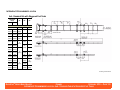
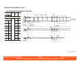
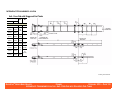
FRAME HEIGHT CALCULATION – AT CENTERLINE OF REAR AXLE - ALL MODELS
FRAME HEIGHT CALCULATION – AT CENTERLINE OF REAR AXLE
All Models
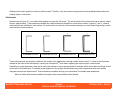
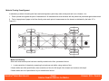
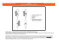
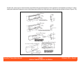
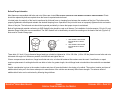
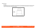
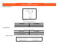
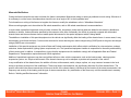
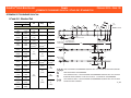
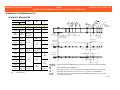
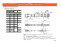
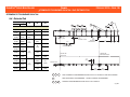
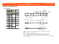
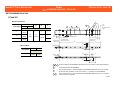
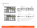
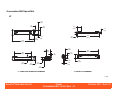
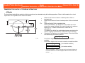
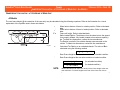
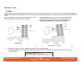
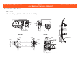
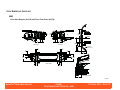
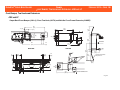
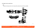
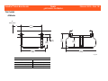
The rear frame height (@ the centerline of the rear axle) may be calculated using the following equations. Refer to the illustration for a visual
explanation of the symbols used in these calculations.
Dr =
D r′ =
′
′
F=
SLR =
R1 =
01_0072
R2 =
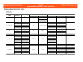
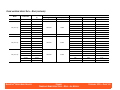
Wheel axis to bottom of frame in unladen position. Refer to tabulated
data.
Wheel axis to bottom of frame in loaded position. Refer to tabulated
data.
Frame rail height. Refer to tabulated data.
Static Loaded Radius. The distance from the wheel axis to the ground
for a properly inflated, fully loaded (loaded to its maximum capacity)
tire. To obtain tire dimensions, contact the tire manufacturer.
Tire Radius (one half of tire outside diameter) NOT mounted on the
vehicle. To obtain tire dimensions, contact the tire manufacturer.
Calculated Tire Radius on an unloaded chassis. The value of R2 is
calculated using the following method.
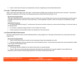
R 2 = R 1 – .2 ( R 1 – SLR )
Z=
Rear Frame Height at the rear axle centerline in unloaded condition.
Z′=
Rear Frame Height at the rear axle centerline in loaded condition.
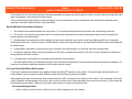
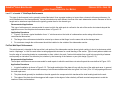
Z = Dr + R2 + F
Z′ = D r ′ + SLR + F
NOTE:
(for unloaded condition)
(for loaded condition)
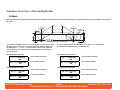
Values calculated for Z and Z′ are strictly for the frame height at the rear
axle centerline. For frame heights at the rear of the frame rail, refer to
“FRAME HEIGHT CALCULATION – AT FRONT AND REAR RAIL ENDS”.