1
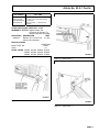
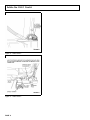
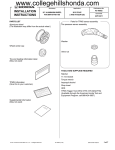
ELECTRICAL—TH!NK VEHICLES—REVISED 72 VOLT LOW CURRENT WIRE HARNESS REPLACEMENT PROCEDURE Article No. 03-2-1 THINK: 2002 TH!NK NEIGHBOR ISSUE Some 2002 TH!NK Neighbor vehicles may exhibit illumination of the leakage icon, failure to power up, intermittent loss of power, gauge malfunction, and other related vehicle system malfunctions. This may be caused by a damaged 72-volt low current harness. ACTION This procedure will help in the removal and installation of the revised 72-volt, low current wire harness which has the relocated service disconnect switch. The revised harness consists of two part numbers: a short harness containing the service disconnect switch, and the longer main harness. SERVICE PROCEDURE WARNING CONTINUE TO USE ALL APPROPRIATE HIGH VOLTAGE SAFETY PROCEDURES WHEN WORKING ON A VEHICLE. WARNING THE BATTERY PACK CONTAINS HIGH-VOLTAGE COMPONENTS AND WIRING. HIGH-VOLTAGE INSULATED SAFETY GLOVES AND FACE SHIELD MUST BE WORN WHEN PERFORMING THE FOLLOWING STEPS. FAILURE TO FOLLOW THIS WARNING MAY RESULT IN SEVERE PERSONAL INJURY OR DEATH. WARNING THE BATTERY PACK ASSEMBLY CAN DELIVER IN EXCESS OF 72 VOLTS OF DC POWER. IMPROPER HANDLING OF THE BATTERY PACK CAN RESULT IN INJURY OR FATALITY. ONLY AUTHORIZED PERSONNEL TRAINED TO WORK WITH BATTERY PACK COMPONENTS ARE PERMITTED TO HANDLE THE BATTERIES. WARNING MAKE SURE THE VEHICLE IS NOT BEING CHARGED. NOTE: The information in Technical Service Bulletins is intended for use by trained, professional technicians with the knowledge, tools, and equipment to do the job properly and safely. It informs these technicians of conditions that may occur on some vehicles, or provides information that could assist in proper vehicle service. The procedures should not be performed by “do-it-yourselfers”. Do not assume that a condition described affects your car or truck. Contact a Ford, Lincoln, or Mercury dealership to determine whether the Bulletin applies to your vehicle. Copyright 2003 Ford Motor Company PAGE 1 Article No. 03-2-1 Cont’d. PART ONE: DISASSEMBLY h. Disconnect the battery cables at locations (B) and wrap the terminals on the cables with electrical tape. Disable Battery Pack. 1. Remove key from ignition. Harness Removal - Front Of Vehicle 2. Remove both seat cushions. 9. 3. Remove seat belt access panel. 4. Remove seat stanchion covers. 10. Remove passenger side cup holder by fully removing the scrivets. 5. Remove seat belt buckle bolts. 6. Remove both front seats. 7. Turn service disconnect switch (SDS) to the off position. 8. Disable the battery pack; refer to steps (a) through (h) referenced from the “power shut down procedure” in the Electrical Section of the Service Manual. Remove front lid. 11. Remove the 72-volt harness connections from the gauge. 12. Unplug the throttle position sensor connector from the accelerator pedal. 13. Cut harness on both sides of Ferrite beads and remove. 14. Remove the leakage sensor lead 10 mm bolt and eyelet from the front of the vehicle. a. Connect the capacitor discharge tool to discharge the motor controller. 15. Unplug the DC/DC converter from the high voltage wire harness. b. Touch the negative probe of the DVOM to the B- (battery negative, labeled “BATT 1 NEG”). 16. Unplug the charger. c. Touch the positive probe of the DVOM to the load side of the 10-amp fuse for the motor controller circuit. This will be the spade connector closest to the front of the fuse holder and it is labeled “GAUGE/MTR-CNTR”. d. The DVOM will display any voltage present. Repeat steps (a) and (b) if DVOM reads more than 0 volts. To discharge the DC/DC converter 1 (standard) or DC/DC converter 2 (optional). e. Touch the negative probe of the DVOM to the B- (battery negative, which is labeled “BATT 1 NEG”). f. Touch the positive probe of the DVOM to the load side of the 10-amp fuse for the DC/DC circuit. This will be the spade connector closest to the front of the fuse holder and it is labeled “DC/DC”. g. The DVOM will display any voltage present. Repeat steps (a) and (b) if DVOM reads more than 0 volts. 17. Remove front part of harness. Harness Removal - Mid Vehicle 18. Unplug battery temperature sensor. 19. Disconnect contactor connector. 20. Disconnect the harness battery positive 6 eyelet from upper contactor stud. 21. Disconnect battery negative eyelet from harness to battery negative 1. 22. Disconnect the connector for the Service Disconnect Switch (SDS) from the harness. If the SDS does not have a connector and is not located on the “H” bracket, cut the SDS harness wires. 23. Remove the riveted SDS box from the frame if applicable and discard box. 24. Remove parking brake from “H” bracket if the SDS is not located on the “H” bracket. 25. Remove “H” bracket, discard if the SDS is not located on the bracket. 26. Remove middle section of harness. 27. Remove the plastic floor pan restriction from where the harness passes through the floor pan. See Figure 1. PAGE 2 Article No. 03-2-1 Cont’d. WARNING THE FRONT AND REAR KICK PANELS SHOULD NOT BE PRIED WITH A SCREWDRIVER BECAUSE THE PANELS MAY CRACK. NOTE PRY LOOSE AND REUSE ALL WIRE TIE RETAINERS THAT ATTACH THE HARNESS TO THE VEHICLE. DISCONNECT SWITCH AND WORKING OUT FROM THERE TO THE FRONT AND BACK OF THE VEHICLE. Harness Installation - Mid Vehicle 1. Attach the Service Disconnect Switch 2E3Z-144S01-HA to the “H” Bracket 2E3Z-54605A38-AD. 2. Install “H” bracket. Torque to 15-22 Lb-ft. (20-30 N•m). 28. Raise the vehicle and remove both front and rear passenger tires. 3. Install parking brake handle and cable. Torque to 18-23 Lb-ft. (24-31 N•m). 29. Remove front passenger wheel well by removing rivets. 4. Remove the Ferrite beads from the new harness before installation. 30. Raise vehicle up to appropriate level to be able to access the controller. 5. Feed the harness 2E3Z-14401-DB through the opened harness hole in the floor pan, see Figure 2. 6. Connect the battery negative eyelet from the harness to the battery negative 1. Torque to 107-132 Lb-in. (12-15 N•m). Harness Removal - Rear Of Vehicle 31. Disconnect the speed sensor/temperature sensor connector. 32. Disconnect the 23-pin connector from the controller. 33. Remove harness and lower vehicle. PART TWO: RE-ASSEMBLY NOTE HARNESS INSTALLATION SHOULD BE PERFORMED BY BEGINNING AT THE SERVICE PAGE 3 Article No. 03-2-1 Cont’d. 7. Connect the battery temperature switch. 24. Connect to the cluster gauge. 8. Connect the contactor switch connector. 9. Connect the 72-volt harness to the SDS connector. 25. Connect the power point to the dash, if vehicle has this option. 26. Rivet wheel well back in place. 10. Connect the harness battery positive eyelet to upper contactor stud. Torque to 71-88 Lb-in. (8-10 N•m). 27. Install front passenger tire. Installation - Front 29. Install front lid. 11. Cut upper rocker molding approximately 1 inch back from the right passenger side seat stanchion and 1/2 inch from the inner edge, see Figure 3. Installation - Rear 12. Raise vehicle. 13. Cut a 45 degree angle cut on the inside corner of the right side upper rocker molding. This is the area where it fits into the right rear wheel well opening, see Figure 4. NOTE BY PERFORMING STEPS 11 THROUGH 13 THE ROCKER CAN SLIDE WITH A TAP OF A SOFT HAMMER TO ALLOW CONNECTORS TO FIT THROUGH THE WHEEL WELL WITHOUT ANY PRYING. 14. Pull the front part of the harness through the front wheel well. 15. Install wire ties 1E3Z-6N697-AA to front part of harness and secure to frame. 16. Install Ferrite beads back onto the original location on the harness with orange tape or tie straps. 17. Drill a new 1/4 inch hole on the cross member and use other existing hole for Ferrite bead mounting, refer to Figure 5. 18. Secure the Ferrite beads to the bottom side of the cross member with 2 large tie straps on each side to support the weight of the beads. 19. Connect the harness to the charger. 20. Lower vehicle. 21. Connect harness to DC/DC converter. 22. Connect harness to the throttle position sensor switch. 23. Connect the leakage eyelet to the frame. PAGE 4 28. Install cup holders. 30. Raise vehicle. 31. Tap the rocker towards the front of the vehicle, exposing only enough to safely feed the connectors through for the rear of the vehicle. 32. Align and pull the harness through the opening at the wheel well. 33. Connect speed sensor/temperature sensor connector. 34. Connect the 23-pin connector to the controller. 35. Tap the rocker back into its original position. 36. Install wire ties to rear and mid-harness and secure against frame. NOTE IT IS RECOMMENDED TO VERIFY REPAIR BEFORE FULLY ASSEMBLING VEHICLE. 37. Install the rear passenger tire. 38. Lower the vehicle. 39. Use battery torque wrench to tighten the battery cable clamps nuts to 12-15 N•m (107-132 Lb-in). 40. Install seats. Torque to 15-22 Lb-ft. (20-30 N•m). 41. Install seat belt buckles. Torque to 19-25 Lb-ft. (26-34 N•m). 42. Install stanchion covers. Torque to 15-18 Lb-ft. (20-24 N•m). 43. Install seat belt access panel. 44. Turn service disconnect switch on. 45. Install both seat cushions. 46. Verify repair. Article No. 03-2-1 Cont’d. PART NUMBER 2E3Z-144S01-HA 2E3Z-14401-DB 2E3Z-54605A38-AD 1E3Z-6N697-AA PART NAME Service Disconnect Switch 72-Volt, Low Current Wire Harness “H” Bracket Wire Tie Strap - (7 Required Per Vehicle) OTHER APPLICABLE ARTICLES: NONE WARRANTY STATUS: Eligible Under The Provisions Of Bumper To Bumper Warranty Coverage OPERATION DESCRIPTION TIME 030201A Replace The 72-Volt Low 2.9 Hrs. Current Wire Harness DEALER CODING CONDITION BASIC PART NO. CODE 14401 01 OASIS CODES: 201000, 201200, 203000, 203100, 203200, 204000, 204100, 205000, 206000, 603300, 607000, 614000 Figure 2 - Article 03-2-1 Figure 1 - Article 03-2-1 Figure 3 - Article 03-2-1 PAGE 5 Article No. 03-2-1 Cont’d. Figure 4 - Article 03-2-1 Figure 5 - Article 03-2-1 PAGE 6