1
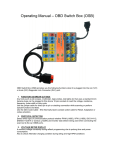
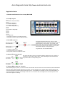
Auto Diagnostic tools http://www.autotool-mall.com
Application Notes
1. Benefits and Features of the Linespi DLC BOB
2. LineSpi Layout
Pin 1
Pin 2 Yellow LED (VPW,PWM)
Pin 3
Pin 4 Green LED (Gnd)
Pin 5 Green LED (Gnd)
Pin 6 Yellow LED (CAN)
Pin 7 Yellow LED (KWP,ISO)
Pin 8
Pin 9
Pin 10 Yellow LED (PWM)
Pin 11
Pin 12
Pin 13
Pin 14
Pin 15
Pin 16 Red LED
- Connection to vehicle via 4-ft cable not shown.
- Connection to scan tool via 6-in cable not shown.
3. Red LED on pin 16
The red LED uses both grounds, pin 4 and 5. This is
accomplished by the use of diodes and effects how the red
LED will respond to ground issues. For example, if the
vehicle wiring to pin 4 has a high resistance problem it will
not effect the red LED because it still has a good ground
path via diode 2 and pin 5, the signal ground.
As a general rule: The red LED will dim if:
• The battery voltage is low
• The wiring to DLC pin 16 is defective.
• Both ground circuits have resistance issues.
4. Green LED on pins 4 and 5
Each ground LED (pin 4 and 5) is connected to battery voltage via pin 16. Therefore, a
ground issue on pin 4 will not affect LED 5. A dim individual green LED will indicate a
circuit problem with the corresponding circuit.
5. Yellow LED on pins 2, 6, 7 and 10
Yellow LED's light up on pins 2, 6, 7 and 10 to show communication with scan tool and for communication protocol identification.
When the yellow LEDs illuminate depends on the vehicle. For some vehicles none or multiple yellow LEDs will illuminate as
soon as the LineSpi is connected and the ignition is turned on. A Ford PWM is an example. Pin 2 and 10 will start flashing as
soon as the ignition is turned on even though a scan tool is not connected. Also, the brightness of the LED depends on the
nature of the signal it is following.
Auto Diagnostic tools http://www.autotool-mall.com
The LineSpi LEDs can be used to quickly identify the communication protocol. The best way to identify the protocol is to set the
scan tool up for LIVE DATA. This will result in a constant data stream between the scan tool and the vehicle. Next, locate the
LED(s) that are flashing.
For example:
• Only LED 7 flashing: Protocol is either KWP or ISO 9141
• LED 2 and LED 10 flashing: Protocol is PWM
The User Manual goes into more detail.
6. Self-Healing Fuse on pin 16
The socket input to pin 16 is protected by a self healing fuse between the socket and the cable. If for some reason a short were
to develop between the pin 16 banana socket and a ground outside the LineSpi the fuse will open protecting the LineSpi, the
DLC connector and associated wiring. Note that if a scan tool is connected to the LineSpi when a short occurs as described
above the power to the scan tool will not be interrupted.
This fuse is rated at 1.5 amps and will open the circuit at 2.7a (temperature dependent). Reset the fuse by disconnecting the
fuse from power and let cool.
7. Stories from the Field #1: Monitoring Voltage during Flashing
When flashing you need to maintain a voltage of at least 12.6 volts up to 14.6. If voltage drops below 12.6 your flash will be
corrupted. Using the AES LineSpi lets you easily monitor voltage with a DVOM. Put the black lead on Pin 4 and the red lead on
Pin 16.
7. Stories from the Field #2: Protect your Scan Tool...
We have heard that when Saturn Body Controller Module fail they may put 12 volts on Pin 2. (something to do with a power
transistor). When a scan tool was connected this voltage fried the scan tool. To check the voltage on Pin 2 with the AES LineSpi
you can connect your DVOM black lead to Pin 4, red lead to Pin 2. Should get 0 to 7 volts (CLASS II DATA). If you get 12 volts
(battery voltage) we urge you not to connect your scan tool.