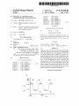
1
USOO8795208B2
(12) United States Patent
(10) Patent N0.:
Walker
(54)
(75)
(73)
(45) Date of Patent:
MECHANICAL CPR DEVICE WITH
VARIABLE RESUSCITATION PROTOCOL
Inventor:
5,716,318 A
5,722,613 A
Rob Walker, Bothell, WA (US)
(US)
Aug. 5, 2014
2/1998 Manning
3/1998 MICha?1
5,743,864 A
4/1998 Baldwrn, 11
5,997,488 A
12/1999 Gelfand et al.
6,390,996 B1
Assignee: Physio-Control, Inc., Redmond, WA
( * ) Notice:
US 8,795,208 B2
5/2002 Halperin et al‘
6,398,745 B1 *
6/2002
6,676,613 B2
1/2004 Cantrell et al.
7,311,680 B2
12/2007 LenhaIt et al.
Subject to any disclaimer, the term of this
(
patent is extended or adjusted under 35
Sherman et al. .............. .. 601/41
Continued
)
FOREIGN PATENT DOCUMENTS
U.S.C. 154(b) by 272 days.
GB
(21) Appl. No.: 10/981,365
(22)
Filed:
8/2008
OTHER PUBLICATIONS
NOV' 3’ 2004
Prior Publication Data
(65)
2446124 A
Hallstrom et al., “Cardiopulmonary Resuscitation by Chest Com
pression Alone or with Mouth-To-Mouth Ventilation”, May 25, 2000,
The New England Journal of Medicine, vol. 342, N0. 21, pp. 1546
US 2006/0094991A1
May 4, 2006
15534
(51) Int. Cl.
(Continued)
A61H 31/00
(52)
(58)
(2006.01)
us CL
Primary Examiner * Quang D Thanh
USPC ........................................... .. 601/41; 601/ 108
(74) Attorney, Agent, or Firm * Baker & Hostetler LLP
Field of Classi?cation Search
CPC
A61H 31/00; A61H 31/004; A61H 31/006;
(57)
ABSTRACT
A61H 2031/00; A61H 2031/001; A61H
2031/003; A61H 2201/1619; A61H
Methods to control the delivery of CPR to a patient through a
mechanical CPR device are described. The method generally
2201/5007; A61H 2203/0456; A61H 2205/08
USPC ~~~~
601/41, 42’ 43s 44s 107: 198; 128/898
see apphcanon ?le for complete searCh hlstOI'Y_
(56)
References Clted
allows for a gradual increase in the frequency of CPR cycles.
The gradual increase can be regulated by protocols pro
grammed within the CPR device such as intermittently start
ing and stopping the delivery of CPR, accelerating the deliv
ery of CPR, stepping up the CPR frequency, increasing the
force of CPR, and adjusting the ratio of compression and
US. PATENT DOCUMENTS
4,060,079 A
4,397,306 A *
8/1983
4,424,806 A
4,570,615 A
1/1984 Newman et al.
2/1986 Barkalow
4,928,674
5,020,516
5,261,394
5,490,820
A
A
A
A
decompression in a CPR cycle. Combinations of each of these
forms may also be used to control the delivery of CPR. This
11/1977 Reinhold, Jr.
5/1990
6/1991
11/1993
2/1996
manner of gradually accelerating arti?cial blood ?ow during
Weisfeldt et a1. ............. .. 601/41
the ?rst minutes of mechanical CPR delivery can serve to
lessen the potential for ischemia/reperfusion injury in the
Halperin et al.
Biondi et a1.
Mulligan et a1.
Schock et a1.
patient who receives mechanical CPR treatment.
45 Claims, 4 Drawing Sheets
21
\ .
CPR
MODE
25
T ON 1
23/
24/
ON
27
T ON 2
29
T ON 3
OFF —
|
T STA RT
W
US 8,795,208 B2
Page 2
References Cited
Emergency Cardiovascular Care. Circulation. Nov. 2, 2010; 122(18
U.S. PATENT DOCUMENTS
Cave DM, et al., Part 7: CPR techniques and devices: 2010 American
Heart Association Guidelines for Cardiopulmonary Resuscitation
(56)
Suppl 3):S685-705.
7,717,855 B2
8,343,081 B2
2003/0135085
2003/0135139
2004/0230140
2005/0165335
2006/0089574
2007/0004992
A1
A1
A1
A1
A1
A1
5/2010
1/2013
7/ 2003
7/ 2003
1 1/ 2004
7/2005
4/2006
1/2007
Caldarone et al.
Walker
Bassuk et al.
Bassuk et al.
Steen
Sherman et al.
Paradis
Van Brunt et a1.
OTHER PUBLICATIONS
and Emergency Cardiovascular Care. Circulation. Nov, 2, 2010;
122(18 Suppl 3):S720-8.
Chapman, F.W. et al., “A Feedback Controller for Ventilatory
Therapy”, Annals of Biomedical Engineering, 1985, 13, 359-372.
Maquet Servo Ventilator 900 C/D/E, Service Manual, Maquet Criti
cal Care AB, May 2009, 55 pages.
Neumar RW, et al.,Part 8: adult advanced cardiovascular life support:
2010 American Heart Association Guidelines for Cardiopulmonary
Resuscitation and Emergency Cardiovascular Care. Circulation.
Nov. 2, 2010; 122(18 Suppl 3):S729-67.
Kern et al., “Ef?cacy of Chest Compression-Only BLS CPR in the
Presence of an Occluded Airway”, 1998, Elsevier Science Ireland
Ltd., Resuscitation 39 (1998), Accpted Nov. 11, 1998, pp. 179-188.*
Zhi-Qing Zhao, Joel S. Corvera, Michael E. Halkos, FaraZ Kerendi,
Ning-Ping Wang, Robert A. Guyton and Jakob Vinten-Johansen,
Ovize M, et al., “Working Group of Cellular Biology of Heart of
European Society of Cardiology. Postconditioning and protection
from reperfusion injury: where do we stand?” Position paper from the
Working Group of Cellular Biology of the Heart of the European
Society ofCardiology. Cardiovasc Res. Aug. 1, 2010; 87(3):406-23.
Part 4: Adult Basic Life Support, Circulation, 2005, 112: IV-18 to
Inhibition of myocardial injury by ischemic po stconditioning during
reperfusion: comparison with ischemic preconditioning, Am J
IV-34.
Physiol Heart Circ Physi01285, 2003, p. H579-H588, The American
Part 6: CPR Techniques and Devices, Circulation, 2005, 112: IV-47
Physiological Society.
to IV-50.
Michael Galagudza, Dmitry Kurapeev, Sarkis Minasian, Guro Valen,
and Jarle Vaage, Ischemic postconditioning: brief ischemia during
reperfusion converts persistent ventricular ?brillation into regular
rhythm, European Journal of Cardio-thoracic Surgery 25 (2004), p.
Segal N, et al., “Ischemic postconditioning at the initiation of
cardiopulmonary resuscitation facilitates functional cardiac and
cerebral recovery after prolonged untreated ventricular ?brillation”,
1006-1010, Elsevier B.V.
Michael E. Halkos, FaraZ Kerendi, Joel S. Corvera, Ning-Ping Wang,
Hajime Kin, Christopher S. Payne, He-Ying Sun, Robert A. Guyton,
Jakob Vinten-Johansen, and Zhi-Qing Zhao, The Society of Thoracic
Surgeons, 2004, p. 961-969, Elsevier Inc.
Gerd Heusch, Postconditioning, Old Wine in a New Bottle?, Journal
of the American College of Cardiology, 2004, vol. 44, No. 5, p.
1111-1112, Elsevier Inc.
Resuscitation. Nov. 2012; 83(11):1397-1403.
Travers AH, et al., Part 4: CPR overview: 2010 American Heart
Association Guidelines for Cardiopulmonary Resuscitation and
Emergency Cardiovascular Care. Circulation. Nov. 2, 2010; 122(18
Suppl 3):S676-84.
Wang JY, et al., “Ischemic postconditioning protects against global
cerebral ischemia/reperfusion-induced injury in rats”, Stroke. Mar.
2008; 39(3):983-90.
Yannopoulos D, et al., “Controlled pauses at the initiation of sodium
Hajime Kin, Zhi-Qing Zhao, He-Ying Sun, Ning-Ping Wang, Joel S.
nitroprusside-enhanced cardiopulmonary resuscitation facilitate
Corvera, Michael E. Halkos, FaraZ Kerendi, Robert A. Guyton, and
neurological and cardiac recovery after 15 mins of untreated
Jakob Vinten-Johansen, Postconditioning attenuates myocardial
ischemia-reperfusion injury by inhibiting events in the early minutes
ventricular ?brillation”, Crit Care Med. May 2012; 40(5):1562-9.
Yannopoulos D, et al., “Ischemic post-conditioning and vasodilator
therapy during standard cardiopulmonary resuscitation to reduce
cardiac and brain injury after prolonged untreated ventricular ?bril
lation”, Resuscitation. Aug. 2013; 84(8): 1143-9. Epub Jan. 29, 2013.
Zhao, Heng, “The Protective Effects of Ischemic Postconditioning
against Stroke: From Rapid to Delayed and Remote Postcondition
of reperfusion, Cardiovascular Research 62, 2004, p. 75-85, Elsevier
B.V.
Andrew Tsang, Derek J. Housenloy, Mihaela M. Mocanu, and Derek
M. Yellon, Postconditioning: A Form of “Modi?ed Reperfusion”
Protects the Myocardium by Activating the Phosphatidylinositol
3-Kinase-Akt Pathway, Circulation Research, 2004, p. 230-232,
ing”, The Open Drug Discovery Journal, 2010, 2, 138-147.
American Heart Association, Inc.
ZhouY, et al., “Postconditioning in cardiopulmonary resuscitation: a
Xi-MingYang, J. Bradley Proctor, Thomas Kreig, James Downey and
Michael V. Cohen, Multiple, Brief Coronary Occlusions During
Early Reperfusion Protect Rabbit Hearts by Targeting Cell Signaling
Pathways, Journal of the American College of Cardiology, 2004, vol.
better protocol for cardiopulmonary resuscitation”, Med Hypoth
eses. Sep. 2009; 73(3):321-3. 2009.03.014. Epub Apr. 24, 2009.
44, No. 5, p. 1103-1110, Elsevier Inc.
Roberto J. DiaZ and Gregory J. Wilson, Modifying the ?rst minute of
reperfusion: potential for myocardial salvage, Cardiovascular
Research 62, 2004, p. 4-6, Elsevier B.V.
International.Search Report and Written Opinion, PCT/US2005/
39633, Intl. ?ling date Nov. 2, 2005.
Of?ce Action dated Apr. 1, 2009 for US. Appl. No. 11/961,687 (8
The Free Dictionary, De?nition of amechanical device, p. 1 of 2, Apr.
9, 2012.
Of?ce Action from US. Appl. No. 11/961,687, mailed Mar. 25, 2010,
9 pp.
Of?ce Action Response for US. Appl. No. 11/961,687 ?led Jun. 25,
2010, 19 pp.
U.S. Appl. No. 11/961,687: Final of?ce action dated Sep. 8, 2010, 10
pages.
U.S. Appl. No. 11/961,687: Non-?nal of?ce action dated Apr. 25,
pgs)
2011, 6 pages.
Responsive Amendment dated Jul. 1, 2009 for US. Appl. No.
U.S. Appl. No. 11/961,687: Final of?ce action datedApr. 13, 2012, 7
11/961,687 (14 pgs.).
pages.
Of?ce Action Response for US Appl. No. 11/961,687, ?led Jun. 25,
2010, 19 pp.
Berg RA, et al., Part 5: adult basic life support: 2010 American Heart
Association Guidelines for Cardiopulmonary Resuscitation and
U.S. Appl. No. 11/961,687: Notice ofAllowance dated Sep. 28, 2012,
5 pages.
* cited by examiner
US. Patent
Aug. 5, 2014
Sheet 1 0f4
US 8,795,208 B2
11
\\ A
16\
LLI
DC
3
5g
10
\
LL]
2
0
LL
TIME
COMPRESSION
'
RELAXATION
11
L
PHASE
u
PHASE
_,
l‘
\
7‘
\
'I
14
L
15
CYCLE
I‘
'
_,
\
VI
13
FIG. 1
21\
CPR
MODE
25
T ON 1
27\
T ON 2
29\v
T ON 3
V
US. Patent
Aug. 5,2014
3Q.
a;
Sheet 2 0f4
US 8,795,208 B2
35\
34
/30
5
§
33
E L
l
l
T START
\
J\
T
T1
l
J
t
32
fTIME
Y
T2
FIG. 3
A
45
42
E3
5
=
46
\
/3°
44
O
LIJ
E
43
l
l
:
T START
TIME
FIG. 4
51
51
g
52
g
S
E
51
52
52
|
|
_
l
T START
'
TIME
FIG. 5
US. Patent
Aug. 5, 2014
Sheet 3 0f4
US 8,795,208 B2
67
65
>
“E’
63
a
E
61
l
\
f
W4
*Yd
W—J
T START T REST 1
T REST 2
T REST 3
62
64
66
FIG. 6
71
\‘
§
3
a
E
Eg
\
MAX
74
=
US. Patent
PDQZH
/
Aug. 5, 2014
5.30”;on
Sheet40f4
Il ‘
A
M
___-.______a
QZDm
US 8,795,208 B2
US 8,795,208 B2
1
2
MECHANICAL CPR DEVICE WITH
VARIABLE RESUSCITATION PROTOCOL
ischemia/reperfusion injury is known to be affected by the
quality of reperfusion experienced after a period of inter
FIELD OF THE INVENTION
rupted blood ?ow. A cardiac arrest patient, who has had no
blood ?ow for several minutes, and who then receives CPR
for some period of time, may be expected to experience
ischemia/reperfusion injury.
The present invention generally relates to methods and
apparatus for performing mechanical cardiopulmonary
Without wishing to be bound by any theory, the following
resuscitation or CPR. More particularly the present invention
relates to the control of the delivery of CPR. Still more par
explanation is offered to illustrate the current understanding
of ischemia/reperfusion injury. Generally, ischemia/reperfu
ticularly, the present invention relates to protocols con?gured
sion injury initiates at the cellular level and chemically relates
most strongly to the transition between conditions of anoxia/
or programmed within the controller of a mechanical CPR
device.
hypoxia (insuf?cient oxygen) and ischemia (insuf?cient
blood ?ow), and conditions of proper oxygenation and blood
?ow. Pathophysiologically, reperfusion is associated with a
BACKGROUND OF THE INVENTION
variety of deleterious events, including substantial and rapid
CPR, as manually applied by human rescuers, is generally
a combination of techniques including arti?cial respiration
(through rescue breathing, for example) and arti?cial circu
increases in oxidant stress, intracellular calcium accumula
tion, and immune system activation. These events can spawn
a variety of injury cascades with consequences such as car
diac contractile protein dysfunction, systemic in?ammatory
lation (by chest compression). One purpose of CPR is to
provide oxygenated blood through the body, and to the brain,
in those patients where a prolonged loss of circulation places
the patient at risk. For example after a period of time without
restored circulation, typically within four to six minutes, cells
in the human brain can begin to be damaged by lack of
oxygen. CPR techniques attempt to provide some circulation,
and in many cases, respiration, until further medical treat
ment can be delivered. CPR is frequently, though not exclu
sively, performed on patients who have suffered some type of
20
apoptosis. Unfortunately, following cardiac arrest, ischemia/
reperfusion injury and the resulting postresuscitation “syn
25
drome” is serious enough to cause recovery complication and
death in many instances.
Hence, there exists a need for an improved mechanical
CPR device and methods for using the same. It would be
desired to develop CPR methods, and particularly CPR meth
ods for use with a mechanical CPR device, that lessen the
sudden cardiac arrest such as ventricular ?brillation where
the patient’s natural heart rhythm is interrupted.
response hyperactivation, and tissue death via necrosis and
30
It has been found that the desired effects of CPR, when
severity of ischemia/reperfusion injury and that offer an
improved level of response and patient treatment. The present
invention addresses one or more of these needs.
delivered manually, can suffer from inadequate performance.
BRIEF SUMMARY OF THE INVENTION
In order to have the greatest chance at success, CPR must
typically be performed with some degree of force for an
extended period of time. Often the time and exertion required
for good performance of CPR is such that the human
35
responder begins to fatigue. Consequently the quality of CPR
performance by human responders may trail off as more time
elapses. Mechanical CPR devices have been developed which
provide chest compression using various mechanical means
40
such as for example, reciprocating thrusters, or belts or vests
which tighten or constrict around the chest area. In these
automated CPR devices, motive power is supplied by a source
other than human effort such as, for example, electrical power
or a compressed gas source. Mechanical CPR devices have 45
the singular advantage of not fatiguing as do human respond
ers. Additionally, mechanical CPR devices may be advanta
geous when no person trained or quali?ed in manual CPR is
In one embodiment, and by way of example only, the
present invention provides a method for controlling the deliv
ery of cardiopulmonary resuscitation through a mechanical
CPR device comprising the steps of: delivering CPR at a ?rst
frequency; and subsequently delivering CPR at a second fre
quency, wherein the second frequency is different from the
?rst frequency. The second frequency may be greater than or
less than the ?rst frequency. Additionally, the method may
include halting the delivery of CPR for a period of time
between the delivery of CPR at a ?rst frequency and the
delivery of CPR at a second frequency. Still further, the
method may include accelerating (or decelerating) the rate of
delivery of CPR from the ?rst frequency to the second fre
quency.
able to respond to the patient. Thus, the advent of mechanical
CPR chest compressions for extended periods of time.
In a further embodiment, still by way of example, there is
provided a method of controlling the administration of CPR
to a patient through a mechanical CPR device comprising
When a patient experiences cardiac arrest, the heart ceases
to pump blood throughout the body. The cessation of blood
?ow is known as ischemia. When CPR chest compressions
temporarily alternating between a period of delivery of CPR
and a period of non-delivery of CPR. The alternating between
a period of delivery of CPR and a period of non-delivery of
CPR devices now allows for the consistent application of
are commenced, some blood ?ow is restored. The restoration
of blood ?ow after a period of ischemia is known as reperfu
50
55
sion. The study of CPR has revealed that after initial resusci
tation from cardiac arrest, a cardiovascular postresuscitation
“syndrome” often ensues, characterized by various forms of
cardiac dysfunction. In many cases, this postresuscitation
of CPR and a period of non-delivery of CPR may occur during
the ?rst minute after mechanical CPR is ?rst delivered to a
patient.
60
dysfunction can lead to heart failure and death. Furthermore,
the study of reperfusion after ischemia has revealed that a
particular kind of injury can develop in the ?rst moments of
reperfusion. This injury, known as ischemia/reperfusion
injury, occurs for reasons not fully understood. It, however, is
CPR may begin once mechanical CPR is ?rst: delivered to a
patient. Additionally, alternating between a period of delivery
65
In still a further embodiment, and still by way of example,
there is provided a device for the delivery of mechanical CPR
that is also con?gured to regulate the delivery of CPR to a
patient comprising: a means for compressing a patient’s
chest; a means for actively decompressing or permitting pas
sive decompression of a patient’s chest; and a controller
known to result in a variety of symptoms that can contribute
linked to the means for compressing, and the means for
to postresuscitation cardiac dysfunction. More importantly,
actively decompressing or permitting passive decompres
US 8,795,208 B2
3
4
sion, and wherein the controller is also con?gured to auto
matically change over time the delivery of mechanical CPR to
the invention or the following detailed description of the
invention. Reference will now be made in detail to exemplary
embodiments of the invention, examples of which are illus
a patient. The device may also include a timer linked to the
controller, and may also include an input device linked to the
controller whereby a user may select a CPR delivery protocol.
trated in the accompanying drawings. Wherever possible, the
The controller may be con?gured to automatically provide
ings to refer to the same or like parts.
same reference numbers will be used throughout the draw
mechanical CPR at a ?rst frequency, and subsequently at a
It has now been conceived that the application of CPR,
second frequency. Additionally, the controller may be con?g
ured to temporarily alternate between delivery of mechanical
CPR and halting delivery of mechanical CPR. Also addition
ally, the controller may be con?gured to accelerate (or decel
erate) the frequency of mechanical CPR. Still further, the
through a mechanical CPR device, can be controlled in a
manner so as to lessen the potential for post-treatment
ischemia/reperfusion injury. In general, an embodiment of
the invention includes accelerating or increasing the delivery
rate, or frequency, of CPR when ?rst responding to a patient
in a manner that results in blood ?ow being gradually, rather
than suddenly, restored. Another embodiment of the inven
controller may be con?gured to alter the ratio of compression
phase to decompression phase in a CPR cycle. And yet still
further the controller may be con?gured to vary the pressure
tion includes temporarily alternating on and off the delivery
of CPR when ?rst responding to a patient in a manner that
applied by the means for compressing.
Other independent features, characteristics, and advan
similarly results in net blood ?ow being gradually, rather than
suddenly, restored. The gradual or the intermittent restoration
of blood ?ow allows the body’s natural metabolism and
tages of the mechanical CPR device with a variable resusci
tation protocol will become apparent from the following
detailed description, taken in conjunction with the accompa
20
nying drawings which illustrate, by way of example, the
principles of the invention.
BRIEF DESCRIPTION OF THE DRAWINGS
25
FIG. 1 is a graphical illustration of a typical compression/
decompression cycle in a mechanical CPR device.
chemical processing mechanisms to better neutralize the
potentially harmful effects of reperfusion and a sudden
increase in the supply of oxygen to the body’s tissues. The
starting point for the gradual or the intermittent restoration of
blood ?ow preferably coincides with the ?rst delivery of CPR
to the patient. The method may include control techniques
that affect variables in mechanical CPR delivery; these con
trol techniques include, for example, a gradual acceleration
FIG. 2 is a graphical illustration of a form of CPR control
(increase) in the CPR delivery rate or also periods of CPR
according to a ?rst exemplary embodiment in which CPR
interspersed with periods of non-delivery of CPR. While the
CPR control techniques described herein may be performed
delivery is alternated between periods of delivery and periods
of non-delivery.
30
at any time, they are preferably to be applied to a patient
during the ?rst minutes of CPR performance.
FIG. 3 is a graphical illustration of a form of CPR control
according to a second exemplary embodiment in which the
frequency of CPR chest compression delivery is changed in
step increments.
35
FIG. 4 is a graphical illustration of a form of CPR control
according to a third exemplary embodiment in which the
frequency of CPR chest compression delivery is accelerated
until reaching a desired frequency plateau.
FIG. 5 is a graphical illustration of a form of CPR control
manipulated so that the patient’s chest cavity is compressed.
40
Other devices may rely on the direct application of force on
the patient’s chest as through a compressor arm. Regardless
of the mechanical means used, the mechanical CPR device
effects a compression of the patient’ s chest cavity. After com
pression, the mechanical CPR device then experiences a
45
period of decompression. During the period of decompres
according to a fourth exemplary embodiment in which the
frequency of CPR chest compression delivery is accelerated
to a ?rst plateau frequency, and is then accelerated to a second
plateau frequency, and is then accelerated to a third plateau
frequency.
sion, the patient’s chest cavity is either allowed to decompress
passively for a period of time, or is actively decompressed
FIG. 6 is a graphical illustration of a form of CPR control
according to a ?fth exemplary embodiment in which the
frequency of CPR chest compression delivery is accelerated
to a ?rst plateau frequency, is then halted, is then accelerated
to a second plateau frequency, is then halted, and is then
accelerated to a third plateau frequency, halted, and ?nally
accelerated to a fourth plateau frequency.
50
through a direct coupling of the mechanical CPR device to the
patient’s chest. In a mechanical device decompression may
be achieved by relieving pressure and/or force for a period of
time. Active decompression in a mechanical device may be
achieved by directly coupling the mechanical device to the
patient’s chest during the decompression phase, for example
FIG. 7 is a graphical illustration of a form of CPR control
according to a sixth exemplary embodiment in which the
force in the compression phase of CPR delivery is increasing
with time; and
The CPR control methods described herein can be adapted
to any mechanical CPR device that provides chest compres
sion. There are various designs of mechanical CPR devices.
Many designs rely on a vest, cuirass, strap, or harness that
surrounds a patient’s chest cavity. The vest/cuirass/harness
can be constricted, compressed, in?ated, or otherwise
55
by use of a suction cup. Other devices may alternate force
between a constriction and an expansion of, for example, a
belt, harness, or vest.
CPR, including mechanical CPR, is thus a cycle of repeat
FIG. 8 is a simpli?ed functional block diagram of a
mechanical CPR device according to an embodiment of the
ing compressions. Referring now to FIG. 1 there is shown a
graphical representation of an exemplary mechanical CPR
present invention
60
DETAILED DESCRIPTION
cycle. The curve 10 represents a plot of varying force or
pressure 11 against time 12. The force/pressure is any mea
sure of force or pressure such as pressure applied to a chest
The following detailed description of the invention is
cuirass or force applied on the chest. A typical cycle 13
includes a compression phase 14 and a decompression phase
merely exemplary in nature and is not intended to limit the
thermore, there is no intention to be bound by any expressed
15 in the device. During compression phase 13, force and/or
pressure is applied; in the example illustrated force is steadily
or implied theory presented in the preceding background of
increased until a plateau pressure 16 is reached. The force is
invention or the application and uses of the invention. Fur
65
US 8,795,208 B2
5
6
held at the plateau 16. As is known in the art, plateau 16
typically represents a maximum pressure that takes into
account considerations of both safety and resuscitation effec
tiveness. After a desired time, force is released, and this
duration of CPR increases. It will also be appreciated that the
relative lengths of each TON period and each TOFF period
may be the same or different. For example, the duration of the
?rst TOFF period may be equal to the duration of the imme
diately following TON period, as illustrated in FIG. 2.
In FIG. 2, the graph shows a switching between on and off
modes beginning at a start time, Tstart. Tstart may preferably
begins the decompression phase 15. A controlled release may
occur, providing a gradual decrease in force, or as illustrated,
a full uncontrolled (and quicker) release takes place. During
the decompression phase 15, pressure decreases. In the
example shown, pressure decays until no pressure exists. The
decompression phase 15 continues for a desired time, and
then a new compression phase 14 begins. The frequency,
measured in cycles/unit time, of the compression/decompres
coincide with the ?rst delivery of mechanical CPR to a
patient, but that need not be the case. Thus, for example,
Tstart, while it indicates a ?rst time with respect to the chart,
may also correspond to some time in the patient’s treatment
history after the ?rst delivery of mechanical CPR. This is also
true for the other ?gures that include a time variable. Thus, the
varied or controlled CPR shown in the ?gures may illustrate
CPR control that occurs at any point during mechanical CPR
sion cycle is a measure of the rate or speed at which CPR is
applied to the patient. Mechanical CPR devices are typically
designed with a preset frequency; the present frequency may
attempt to mimic the frequency of an ideal human-performed
delivery.
CPR. Thus, a mechanical CPR device may come with a preset
The protocol discussed in FIG. 2 deals with a stuttered
cycle frequency of approximately one hundred (100) cycles
on/ off delivery of CPR. However, CPR delivery may also be
varied with respect to other CPR variables, beyond the on/off
mode. As discussed, the mechanical delivery of CPR gener
per minute. Additionally, some mechanical CPR devices are
designed to include a regular, periodic pause for ventilation in
their protocols. For example, the device may provide for a
20
ally comprises cycles of compression and decompression.
The rate or frequency of this cycle may be varied. Addition
ally, the individual components of the cycle, such as force of
pause after a set of compressions. Other devices are designed
to provide continuous compressions without pause for venti
lation. The CPR device with variable resuscitation protocol
described herein is equally applicable to either type of
the compression stroke, may be varied. Finally, the ratio of
25
patient and activated, it begins to provide CPR at the preset
frequency.
Various mechanical CPR devices are described in U.S. Pat.
Nos. 5,743,864; 5,722,613; 5,716,318; 4,570,615; 4,060,079;
30
and U.S. patent application Ser. Nos. 2003/0135139 A1 and
2003/0135085 A1 . These U.S. patents and patent applications
are incorporated herein by reference.
Referring now to FIG. 2 there is shown a graphical repre
sentation of controlled CPR delivery according to an illustra
compression/decompression components (the duty cycle)
may also be varied.
Referring now to FIG. 3, there is shown a graphical illus
tration of a varied CPR delivery according to another embodi
ment of the invention. FIG. 3 represents a plot 30 of the
mechanical CPR device. Once the device is positioned on a
frequency 31 of the CPR cycle (compression and decompres
sion phases of the device) against time 32. In general terms,
FIG. 3 illustrates a step up in the delivery of CPR where the
frequency increases from a lower rate to a higher rate. Thus,
CPR delivery begins with a frequency1 33. After a period of
tive embodiment of the invention. The graph is a plot of CPR
mode 21 against time 22. In this embodiment, CPR delivery is
time, T1, the CPR frequency is stepped up to frequency2 34.
After a next period of time, T2, the CPR frequency is
increased again to frequency3 35. Jumps, or changes, in fre
stuttered between on and off modes 23, 24. The on mode 23
here means a mode in which CPR is being applied to the
patient, and off mode 24 means a mode in which there is no
preferred embodiment, a maximum frequency is reached and
then held without further higher jumps.
35
quency can continue for any number that is desired. In a
40
application of CPR. Preferably the switching between on and
FIG. 3 illustrates an embodiment of a series of step changes
off modes 23, 24 occurs for a period of time after which the
device remains permanently in the on mode. Thus, as shown,
in frequency that gradually ramp up until a ?nal frequency is
reached. While a positive change in frequency has been illus
trated, a step change may also be negative, moving to a lower
frequency. In the example illustrated in FIG. 3 time periods
for each successive frequency may be of increasing duration,
as preferred, where T2>T1. However, the time intervals may
the protocol begins with CPR being applied for a ?rst interval
of time 25, represented as TON1. There follows an interval,
45
TOFFl 26, in which CPR is not applied. Next, CPR is again
applied for a period TON2 27. At this point, in some embodi
ments, the CPR device remains on, without further interrup
tion to the application of CPR. However, in other embodi
ments, CPR may again switch between an off and on state.
be of the same or different durations, including the case in
50
Thus, in some embodiments, after TON2 there follows
TOFF2 28. Applying CPR again, after TOFF2, there follows
TON3 29. This alternating or switching between applying
ments, the change in frequency may also follow a more con
and halting CPR can continue for as many iterations as
desired.
55
It will be appreciated that the lengths of time represented
by TON1 25 and TON2 27 may be the same or different. In a
preferred embodiment, TON2 is greater than TON1; and if
TON3 is present, TON3 is greater than TON2. In this manner,
there is a ramp up in CPR delivered to the patient in that each
60
period during which the patient receives CPR is increased in
duration.
In similar manner, duration of off periods can be the same
or different. Again, in a preferred embodiment, duration of off
intervals become successively shorter (i.e., TOFF1>TOFF2).
Again, by shortening successive off periods, the patient expe
riences a gradual ramp up in the active delivery of CPR. The
which a successive time period (T2) is shorter than a previous
time period where T2<T1.
In the embodiment illustrated in FIG. 3, the change in duty
cycle frequency is a series of steps; however, in other embodi
tinuous acceleration, without jumps or discontinuities. Refer
ring now to FIG. 4 there is shown a graph that illustrates other
embodiments of changes in CPR frequency. As in FIG. 3, the
graph in FIG. 4 illustrates CPR that begins at a start time,
preferably the time at which mechanical CPR is ?rst applied
to a patient. There follows an acceleration period. Three pos
sible acceleration forms are illustrated, a “front loaded”
acceleration 42, a linear acceleration, 43, and a “back loaded”
acceleration 44. The term “front loaded” indicates that there
is a rapid (non-linear) increase in the cycle, such as exponen
tial growth, followed by a gradual approach to a steady fre
65
quency. The term linear indicates that there is a steady rate of
increase, as represented by a linear function. And the term
“back loaded” indicates that the acceleration occurs later
US 8,795,208 B2
7
8
during the time that acceleration occurs, again as represented
in example by an exponential or other non-linear function.
Each period of acceleration ends at point 45. Following that,
other relationships are possible in other embodiments). In this
manner, CPR chest compression frequency can be increased
there is shown a steady application of CPR at a constant
As mentioned above, CPR delivery may also be controlled
through variation of the compressive force applied to the
patient through the CPR device. Referring now to FIG. 7,
over time.
frequency 46. It will be understood, however, that the admin
istration of CPR may continue to be modi?ed and shaped
there is shown a plot of force versus time that illustrates an
beyond what is illustrated.
A further embodiment, that combines elements of the step
increase in peak force applied by the mechanical CPR device
over time. The curve 73 illustrates a growing magnitude of
increase and continuous increase, is shown in FIG. 5. In this
?gure, the delivery of CPR is controlled whereby a series of
successive oscillations; this represents that more force/pres
sure is being applied to successive mechanical CPR cycles.
plateaus 51 at successively increasing frequencies are
Force/pressure 71 grows until it reaches a desired maximum
reached. Each successive plateau represents an increase in
74. From that point forward, it would be preferred to maintain
the peak force/pressure at the desired maximum.
FIG. 7 represents the magnitude of peak force growing in a
relatively linear fashion in successive cycles. However, it will
be appreciated that other rates of changes in peak force are
possible. For example, peak force may increase or decrease
cycle frequency. However, there is added in FIG. 5 intermit
tent periods of acceleration 52 between each plateau. The
form of intermittent acceleration 52 is shown as non-linear
growth in the ?gure; however, other forms of frequency accel
eration may be applied. The time at each frequency plateau
may vary. And, as stated before, changes in frequency need
not be exclusively to increase the frequency. Frequency may
over time in a step wise manner. Likewise force may be
20
exponential growth or decay.
be decreased, or even halted.
Now it will also be appreciated that on/off mode control
may also be combined with any of the forms of control shown
in FIGS. 3, 4, and 5. Thus, for example, at any point in the
operation illustrated in FIG. 3, 4, or 5, there could be inserted
an “off” interval. And after a period of being in off mode,
Also, CPR may be controlled through variations in the
compression/decompression cycle. The relative length of the
compression phase may change with respect to its corre
25
changes. Thus, in one embodiment, early in mechanical CPR
treatment, it may be desired to have a relatively shorter com
pression phase compared to later compression phases. The
30
frequency when the “off” mode began. It may be preferred,
for example, to begin delivery of chest compressions at a
lower cycle frequency than was being done just prior to “off”
mode.
compression cycle to the next. As before changes can occur
tions and decelerations (each of which may be linear or non
35
While the term “off ’ or “off mode” or other similar terms,
40
accelerations, stepped plateau frequencies, and off periods
45
a time Tstart. The frequency of the CPR accelerates to a ?rst
frequency plateau 61 at F1 where it is held constant for a
also be linked to an input device which allows a user to select
a form of CPR delivery parameter to be varied and the manner
or rate at which it is to be varied.
Referring now to FIG. 8 there is shown a simpli?ed func
tional block diagram of a mechanical CPR device according
desired period of time. CPR is then halted for a period of time,
Trest1 62. CPR then begins again. At this point, CPR begins
to a second frequency plateau 63 at frequency level F3. Again,
the CPR frequency is held constant for a desired period of
time. After that time, CPR again halts for a time, Trest2 64.
This pattern is next shown as repeating. After Trest2 64, CPR
begins anew, at a frequency lower than second frequency
of the CPR device. The controller can thus regulate the deliv
ery of CPR including control of parameters such as cycle
frequency, on/ off delivery of CPR, compression and decom
pression phase, and compression force. The controller may
Referring now to FIG. 6, there is shown an embodiment of
a more complex control of the CPR frequency that combines
at a frequency F2 that is below F1 61, and the CPR accelerates
linear).
In operation, a mechanical CPR device according to an
embodiment of the invention includes a controller. The con
troller is linked to other device components so as to be able to
control compression means and relaxation means that are part
necessarily mean that the device powers off or turns off.
with no CPR delivery. In this embodiment, CPR is applied at
relative duration of the compression phase may then gradu
ally be increased (or decreased) from one compression/de
through various functions including step changes, accelera
has been used herein, it will be appreciated that this does not
Rather, it means that delivery of CPR is halted or suspended;
CPR delivery is off. Preferably, the CPR device would at all
times remain in a powered up, energized condition.
sponding decompression phase. This change in the cycle can
also occur so that the overall cycle time remains constant or
delivery of chest compressions may be commenced again.
Further, when stutter control (mixed on/off control) is uti
lized, along with a control that varies the cycle frequency, the
frequency at a second start point need not coincide with the
increased or decreased non-linearly, such as, for example, by
50
to an embodiment of the present invention. CPR device 80
includes controller 81 with a linked input device 82. Control
ler 81 is further linked to valve 83 and pump 84. A power
supply 85 provides power to pump 84. A compression apply
ing element 86 is also linked to the device 80, as through valve
83. Compression applying element 86 may comprise any of
55
the chest shaping devices mentioned before, such as a vest,
plateau 63, accelerates, plateaus 65, and stops for a Trest3 66.
cuirass, strap, harness, or compression arm. In operation,
This cycle can then be repeated as many times as desired.
pump 84 provides a force, such as pressure, through valve 83
Eventually, a maximum frequency FMAX 67 is reached. As
shown in FIG. 6, the frequency is held constant at the maxi
and into compression applying element 86 thereby deforming
the compression applying element 86 and compressing the
mum frequency 67 FMAX, and no further rest periods are
taken.
In the embodiment illustrated in FIG. 6, rest periods,
Trest1, Trest2, etc., successively grow shorter. Other relation
ships between rest period durations are possible in other
embodiments. And, the time during which CPR is delivered
between rest periods, which includes the acceleration phase
and plateau phase, grows longer in successive cycles (though
60
chest. If a device such as a belt is used, it will be understood
that force constricts the belt. When desired, valve 83 also
releases the pressure thus allowing compression applicator 86
to de?ate (relax) and thereby release compressive force on the
chest cavity. Additionally, FIG. 8 shows a mechanical CPR
65
means 87. The mechanical CPR means 87 represents the
combination of power 85, pump 84, valve 83, and apparatus
86. Mechanical CPR means 87 is also linked to controller 81.
US 8,795,208 B2
10
Controller 81 is con?gured such that CPR delivery follows
a desired pattern. A con?gured pattern may be any of the CPR
controls and protocols discussed herein, and variations of the
4. A method of controlling the administration of cardiop
ulmonary resuscitation (CPR) to a patient through a mechani
cal CPR device according to a CPR protocol programmed in
a controller of the mechanical CPR device, the CPR protocol
same. In a preferred embodiment, the controller 81 includes
software and/or hardware that allows for selection and deliv
comprising:
ery of a particular CPR delivery protocol. Also, preferably,
delivering chest compressions to the patient with the
the controller allows a user to select from more than one CPR
mechanical CPR device for a ?rst period of time during
a CPR administration period;
delivery forms by an appropriate input 82.
It is also preferred that a timer (not shown) be included in
after expiration of the ?rst period of time, halting delivery
controller 81 or otherwise linked to controller 81. A timer can
of chest compressions for a second period of time during
the CPR administration period; and
provide time information needed to follow a desired CPR
protocol.
after expiration of the second period of time, resuming the
delivery of chest compressions to the patient with the
In operation, the preferred delivery of mechanical CPR
may be selected depending, for example, on how the patient
mechanical CPR device uninterrupted for the remainder
of the CPR administration period, wherein the remain
der of the CPR delivery period is longer than the ?rst
had been treated prior to the arrival of the CPR device. A
patient who had been receiving manual CPR for an extended
period of time may be treated differently than a patient who
has not received any CPR. In the former case, a quick ramp up
time, or even no ramp up time, may be desired; and in the
latter case a relatively more gentle, extended ramp up tech
period of time during the CPR administration period.
5. The method according to claim 4 further comprising:
after expiration of the second period of time and before the
20
nique may be desired.
In view of the foregoing, it should be appreciated that
mechanical CPR device for a third period of time during
the CPR administration period; and
methods and apparatus are available that allow a mechanical
CPR device to follow a variable resuscitation protocol. While
a ?nite number of exemplary embodiments have been pre
after expiration of the third period of time, halting delivery
25
sented in the foregoing detailed description of the invention,
it should be appreciated that a vast number of variations exist.
It should also be appreciated that the exemplary embodiments
30
Rather, the foregoing detailed description will provide those
skilled in the art with a convenient road map for implementing
exemplary embodiments of the invention. It should also be
understood that various changes may be made in the function
and arrangement of elements described in an exemplary
embodiment without departing from the scope of the inven
35
40
10. The method according to claim 9 wherein the ?rst
frequency and the second frequency are different.
11. The method according to claim 10 wherein the ?rst
frequency is less than the second frequency.
12. The method according to claim 10 wherein the ?rst
45
frequency is greater than the second frequency.
CPR device, the CPR protocol comprising:
13. The method according to claim 4 wherein the second
period of time is greater than 10 seconds.
14. A method of administering cardiopulmonary resusci
tation (CPR) to a patient through a CPR device according to
and
after the step of alternating between the period of delivery
of chest compressions and the period of non-delivery of
chest compressions, delivering an uninterrupted series
of chest compressions to the patient with the mechanical
CPR device for the remainder of the CPR delivery
period, wherein the remainder of the CPR delivery
50
delivering chest compressions to the patient with the CPR
device during a ?rst time segment within a CPR admin
55
60
during the ?rst minute after mechanical CPR is ?rst delivered
to the patient.
istration period;
refraining from delivery of chest compressions and from
delivery of ventilations to the patient during a second
time segment with the CPR administration period, the
second segment immediately following the ?rst seg
ment; and
delivering chest compressions to the patient with the CPR
device during a third time segment within the CPR
administration period, the third segment immediately
mechanical CPR is ?rst delivered to the patient.
3. The method according to claim 1 wherein alternating
between the period of delivery of chest compressions and the
period of non-delivery of chest compressions occurs only
a CPR protocol programmed in a controller of the CPR
device, the CPR protocol comprising:
period is longer than the period of delivery of chest
compressions during the initial portion of the CPR deliv
ery period.
2. The method according to claim 1 wherein alternating
between the period of delivery of chest compressions and the
period of non-delivery of chest compressions begins once
9. The method according to claim 4 wherein the step of
delivering chest compressions for a ?rst period of time further
comprises delivering chest compressions at a ?rst frequency,
and wherein the step of resuming delivery of chest compres
sions further comprises delivering chest compressions at a
second frequency.
What is claimed is:
alternating between a period of delivery of chest compres
sions to the patient with the mechanical CPR device and
a period of non-delivery of chest compressions to the
patient for an initial portion of the CPR delivery period;
time.
8. The method according to claim 5 wherein the length of
the fourth period of time is less than the length of the second
period of time.
tion as set forth in the appended claims.
1. A method of controlling the administration of cardiop
ulmonary resuscitation (CPR) to a patient through a mechani
cal CPR device during a CPR delivery period according to a
CPR protocol programmed in a controller of the mechanical
of chest compressions for a fourth period of time.
6. The method according to claim 5 wherein the fourth
period of time is the same length as the second period of time.
7. The method according to claim 5 wherein the fourth
period of time is greater in length than the second period of
are only examples, and are not intended to limit the scope,
applicability, or con?guration of the invention in any way.
step of resuming the delivery of chest compressions
uninterrupted, delivering chest compressions with the
following the second segment, wherein the third time
period is longer than the ?rst time period.
65
15. The method of claim 14 wherein the step of delivering
chest compressions during the third segment further com
prises:
US 8,795,208 B2
11
12
after expiration of the third period of time, halting delivery
alternating between a time segment of delivery of chest
compression and a time segment of refraining from
delivery of chest compression and from delivery of ven
tilations.
16. The method of claim 15 further comprising repeating
of chest compressions for a fourth period of time during
the CPR administration period.
26. The method according to claim 25 wherein the fourth
period of time is the same length as the second period of time.
27. The method according to claim 25 wherein the fourth
the alternating step.
period of time is greater in length than the second period of
17. The method of claim 14 wherein the ?rst, second and
time.
28. The method according to claim 25 wherein the length of
the fourth period of time is less than the length of the second
third segments occur within the ?rst minute after commence
ment of chest compression delivery.
18. The method according to claim 14 wherein the step of
period of time.
delivering chest compressions during a ?rst segment includes
delivering chest compressions at a ?rst frequency, and
wherein the step of delivering chest compressions during a
29. The method according to claim 25 wherein the step of
delivering chest compressions for a ?rst period of time further
comprises delivering chest compressions at a ?rst frequency,
and wherein the step of resuming delivery of chest compres
sions further comprises delivering chest compressions at a
third segment includes delivering chest compressions at a
second frequency.
19. The method according to claim 18 wherein the ?rst
second frequency.
frequency is less than the second frequency.
20. A method of administering cardiopulmonary resusci
tation (CPR) to a patient through a CPR device according to
a CPR protocol programmed in a controller of the CPR
20
device, the CPR protocol comprising:
ration of the second period of time, resuming the delivery of
chest compressions with the CPR device uninterrupted for the
delivering chest compressions to the patient with the CPR
device during a ?rst time segment within a CPR admin
istration period;
25
refraining from delivery of chest compressions to the
patient and from delivery of ventilations to the patient
during a second time segment within the CPR adminis
tration period, the second time segment immediately
following the ?rst time segment;
delivering chest compressions to the patient with the CPR
30
device during a third time segment within the CPR
administration period, the third time segment immedi
ately following the second time segment; and
refraining from delivery of chest compressions to the
patient and from delivery of ventilations to the patient
35
during a fourth time segment within the CPR adminis
tration period, the fourth time segment following the
third time segment.
21. The method of claim 20 wherein the step of delivering
40
comprises:
for the ?rst minutes of CPR performance during a CPR
administration period, iteratively switching between an
45
the alternating step.
23. The method of claim 20 wherein the initial, second and
third time segments occur within the ?rst minute after com
50
mencement of chest compression delivery.
24. A method of controlling the administration of cardiop
ulmonary resuscitation (CPR) to a patient through a mechani
cal CPR device during a CPR administration period accord
ing to a CPR protocol programmed in a controller of the
38. The method of claim 37, wherein each iteration of the
55
period of time during the CPR administration period;
after expiration of the ?rst period of time, halting delivery
of the off mode.
39. The method of claim 36, wherein a frequency of the
chest compressions for each iteration of the on mode is pro
gressively greater than a frequency of the chest compressions
60
ond period of time being substantially equal in length to
for the previous iteration of the on mode.
40. The method of claim 36, wherein the on mode includes
delivering ventilations to the patient with a mechanical CPR
device, and wherein the off mode includes delivering venti
lations to the patient with the mechanical CPR device.
the ?rst period of time.
25. The method according to claim 24 further comprising:
chest compressions for a third period of time during the
CPR administration period; and
after the ?rst minutes of CPR performance during the CPR
administration period, permanently remaining in the on
mode during the administration of CPR to the patient.
37. The method of claim 36, wherein each iteration of the
on mode is progressively longer than the previous iteration of
off mode is progressively shorter than the previous iteration
delivering chest compressions to the patient for a ?rst
after expiration of the second period of time, delivering
on mode in which chest compressions are delivered to
the patient and an off mode in which no chest compres
sions are delivered to the patient; and
the on mode.
mechanical CPR device, the CPR protocol comprising:
of chest compressions to the patient for a second period
of time during the CPR administration period, the sec
remainder the CPR administration period, wherein the
remainder of the CPR delivery period is longer than the sum
total of the ?rst and second periods of time.
33. The method of claim 20, further comprising after expi
ration of the fourth time segment, resuming the delivery of
chest compressions with the CPR device uninterrupted for the
remainder the CPR administration period, wherein the
remainder of the CPR delivery period is longer than the sum
total of the ?rst, second, third and fourth time segments.
34. The method of claim 33, wherein the third time seg
ment is longer than the ?rst time segment.
35. The method of claim 34, wherein the second time
segment is longer than the fourth time segment.
36. A method of controlling the administration of cardiop
ulmonary resuscitation (CPR) to a patient according to a CPR
protocol programmed in a controller of the mechanical CPR
device, the CPR protocol comprising:
chest compressions during the third time segment further
alternating between a time segment of delivery of chest
compression and a time segment of refraining from
delivery of chest compression and from delivery of ven
tilations.
22. The method of claim 21 further comprising repeating
30. The method according to claim 29 wherein the ?rst
frequency and the second frequency are different.
31. The method according to claim 29 wherein the ?rst
frequency is less than the second frequency.
32. The method of claim 24, further comprising, after expi
65
41. The method of claim 36, wherein the on mode includes
delivering ventilations to the patient with a mechanical CPR
device, and wherein the off mode includes refraining from
delivery of ventilations to the patient.
US 8,795,208 B2
13
14
42. A mechanical cardiopulmonary resuscitation (CPR)
device comprising:
a chest compression mechanism for delivering chest comPmSSionS to a Patient during a CPR delivery PeriOd; and
44. The CPR device of claim 42, Wherein the beginning
portion of the CPR protocol consists of alternating between
periods of delivery of chest compressions and periods of
non-delivery of chest compressions during.
a controller that operates the chest compression mecha- 5
nism according to a CPR protocol programmed Within
the CPR device, Wherein the CPR protocol includes:
a beginning portion during the ?rst minutes of the CPR
45. A mechanical cardiopulmonary resusc1tatlon (CPR)
device comprismg:
means for delivering chest compressions to apatient during
delivery period, Wherein the beginning portion proa CPR delivery period; and
vides a gradual increase in net blood ?ow to the 10
means for automatically controlling the delivery of chest
patient to lessen the potential for reperfusion injury to
compressions to provide:
the patient relative to immediately restoring net blood
?ow to the patient at the beginning portion Ofthe CPR
a gradual increase in net blood ?oW to the patient to
delivery period; and
a remaining portion following the beginning portion,
lessen the potential for reperfusion injury to the
patient relative to immediately restoring net blood
Wherein the remaining portion provides a greater net 15
HOW to the patient at a beginning portion of the CPR
blood ?ow than With the beginning portion, Wherein
delivery period, and
the net. blood is constant
over
the remaining portion,
. .
.
Wherein the remaining portlon extends from the end
of the be innin Onion until the end of the CPR
delivery piriod g p
20
43. The CPR device of claim 42, Wherein the CPR protocol
comprises a gradual acceleration in a delivery rate of chest
compressions during the beginning portion.
a reater net blood ?ow than With the be innin
ortion
g
g
gp
over a remaining portion of the CPR delivery period,
and Wherein the remaining portion extends from the
in? Ofthe béggmmg pomon unnl the end Ofthe CPR
e wery peno '
*
*
*
*
*