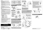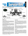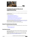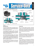
1
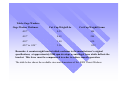
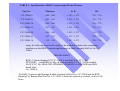
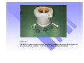
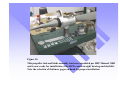
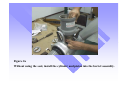
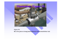
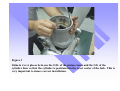
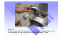
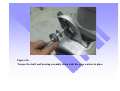
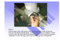
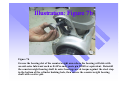
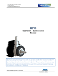
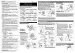
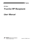
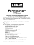
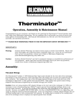
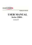
RSW PRODUCTS, INC.
2161 Cromwell
Houston, Texas 77093
Tel: 281-590-6428 Fax: 281-590-6739
Installation Instructions
For RSW Counterweight Bearing & Shaft Assembly Kit
Part No. C.P. 22000
7-10-1999
S.T.C. No. SP09397SC, issued 11/18/92
INSTALLATION INSTRUCTIONS NO. 22000-I
Instructions For The Assembly and Installation of RSW Counterweight Bearings & Shaft
Assembly Kit Part No. C.P. 22000 in Place of the Hamilton Standard Propeller (HSP)
Bearing and Shaft Assemblies in Hamilton Standard Propellers Model No.
2D30, 12D40, 2E40 and 3D40.
NOTE: This unit is designed to fit RSW Cylinder Shaft Bushing Part No. C.P. 22001-2, which
replaces the HSP Bushing-Counterweight Bearing Shaft, Part No. 51124.
ESSENTIAL REFERENCE MATERIALS:
1.
Hamilton Standard Service Manual No. 110D - Counterweight Propellers.
RSW Drawing No. C.T. 37200, and RSW Installation Instructions No. 2200A. (If
cylinder first needs to be modified per S.T.C. No. SP7836SW dated 6/11/91 and RSW
Bushing Part No. C.P. 22001-2 installed).
PREPARATORY REQUIREMENTS PRIOR TO INSTALLATION:
Disassemble the propeller in the manner specified in the HSP Service Manual 110D,
Section VI, Pages 61-62, to make removal of the counterweight bearing shaft and thrust
assemblies possible.
For re-assembly, the following (as applicable) HSP parts will not be required:
HSP Part No. - NOT REQUIRED:
Part Name:
1.
53599, 51777, 51776 or 53215
Counterweight Bearing Retainer
Spacer
2.
50029 or 53216
Counterweight Bearing Race (Outer)
3.
51792 or 53214
Counterweight Bearing Retainer
Assembly
4.
50027 or 53213
Counterweight Bearing Race (Inner)
5.
50358 or 53546
Counterweight Bearing Shaft
6.
51129, 51129-15, or 51129-30
Thrust Washer
52771
Thrust Bearing Assembly
At this point, if not already accomplished, it is necessary to have the cylinder modified in
accordance with S.T.C. No. SP7836SW to incorporate the RSW Cylinder Shaft Bushing Part No.
C.P. 22001-2, which replaces the HSP Bushing-Counterweight Bearing Shaft Part No. 51124.
Units must be installed/replaced in full sets only. (See Figure 1a)
The following RSW parts will replace the above HSP parts in the course of the installation of
the RSW Counterweight Bearings & Shaft Assembly Kit Part No. C.P. 22000:
RSW Parts - REQUIRED:
Part Name:
A. C.P. 22002-2
Counterweight Bearing Shaft, Silver Plated.
B. C.P. 22004-2
Counterweight Outer Bearing Race, Silver
Plated, Trebor Coated.
C. C.P. 22005-0 thru C.P. 22005-30
Thrust Washer, Silver Plated, Trebor Coated.
D. C.P. 22006
Thrust Bearing Assembly (Matched Set), Silver
Plated, Trebor Coated.
NOTE:
Items A and B are factory pre-assembled.
INSPECTION REQUIREMENTS PRIOR TO INSTALLATION:
All visible parts, regardless of disassembly requirements, should be visually examined for
damage, excessive wear, corrosion and correctness of fit. All surfaces and edges that have nicks,
burrs, roughness, scoring or corrosion (within acceptable tolerances) should be smoothed out.
Refer to Cleaning and Inspection sections in Hamilton Standard Propeller Service Manual 110D,
as applicable, Pages 63-75. Particular attention needs to be paid to the shim plate and thrust
washer face of the counterweight bracket. If it is galled or worn, it should be reworked as
instructed in HSP Manual 110D pages 67 (2) (a) 1. through (b), and page 76 (6) (a) and (b). An
uneven surface will prevent maximum efficiency of operation and will lead to excessive wear of
the thrust washer and its coated surface. It is also highly recommended that the counterweight
bracket bearing slot and counterweight bracket shim plate and thrust washer face be coated with
Trebor for better surface compatibility.
INSTALLATION:
1.
Counterweight Thrust Bearing Assembly, Part No. C.P. 22006: Raise and move
the cylinder so that the RSW Bushing-Counterweight Bearing Shaft, Part No.
C.P. 22001-2, is away from the bracket arms, and then rest it on the brackets.
Insert the RSW Bearings, Part No. C.P. 22006, which replace Hamilton
Standard Bearings Part No. 52771, as illustrated in Hamilton Standard Propeller
Service Manual 110D, Section VI, Page 107.
2.
Thrust Washers: Install the RSW Thrust Washer, Part No. C.P. 22005-( )
against the face of the RSW Counterweight Thrust Bearing Assembly, Part No.
C.P. 22006. Hold the RSW Thrust Washer, Part No. C.P. 22005-( ) and the
RSW Thrust Bearing Assembly, Part No. C.P. 22006 in place and turn the
cylinder back into position between the brackets and set it so the bushing bores
are in line with the slots in the brackets. The cylinder boss position numbers
should correspond with the bracket arm position numbers, per Hamilton Standard
Propeller Service Manual 110D, Section VI, Page 107.
Counterweight Bearing Assemblies: Line up cylinder with counterweight brackets (HSP
Part No. 50390, 51430 or 50605). Insert the RSW Counterweight Shaft Assembly
Units consisting of RSW Outer Bearing Race Part No. C.P. 22004-2 and RSW Shaft,
Part No. C.P. 22002-2, through the counterweight bracket arms, and then through the
RSW Thrust Washers, Part No. C.P. 22005-( ), and the RSW Thrust Bearing
Assemblies, Part No. 22006.
Cylinder Centering Guide:
NOTE: Assemble propeller minus cylinder and piston assembly per HS manual 110D.
(See Fig. 1b)
1. Install cylinder assembly with piston and RSW Piston Crown in place, but without the
seal, into the propeller barrel. (See Figures 2a & 2b)
2. Shim in 4 or 6 places between O.D. of RSW Piston Crown and I.D. of cylinder liner
so the cylinder is positioned in the absolute center of the hub, to insure no wedging or
seizing occurs during propeller operation. (See Figure 3)
3. Ascertain that the flat sides of the cylinder are parallel with the inboard sides of the
counterweight brackets.
4. Select appropriate RSW C.P. 22005-( ) thrust washer thickness with the aid of the
.006" GO horseshoe-shaped gage and the .008" NO-GO gage, with the counterweight
shaft assembly installed loosely. (See Figure 4)
5. Test at the bottom and top of the counterweight arm to insure that the counterweight
arm is installed correctly (concentric) on the blade butt (the assumption here is that the
counterweight arm has been inspected and found to be in tolerance for straightness and
wear according to HSP Manual 110D)
6. Fit the RSW C.P. 22000 counterweight shaft & bearing assembly with the aid of the
gage washers. ( See table on Page 5 of these instructions: Gage Washers).
7. Slip gage washer over counterweight shaft for clearance between counterweight
shaft outer bearing race (inboard) and bottom of counterweight bracket bearing track
(outboard). (See Figures 5a & 5b)
8. Fit counterweight shafts by means of grinding or filing the ends of the shafts as
necessary. When the counterweight shaft with the gage washer in place is torqued
against the steel stop in the bottom of the cylinder, the outer counterweight shaft bearing
race, which is positioned in the counterweight bracket slot, must rotate when turned
between the thumb and index finger. After all the counterweight bearing shaft
assemblies have been torqued with the spacer gages in place to the point where the outer
counterweight shaft bearing races can still be turned, remove the spacer gages one at a
time. (See Figure 6)
At this time, coat (brush) the counterweight bearing shaft (part no. C.P.22002-2), the
counterweight outer bearing race (part no. C.P.22004-2), and the counterweight
bracket arm outboard counterweight bearing slot with a good anti-seize lubricant such
as Fel-Pro Moly Paste, P/N 51048 or equivalent. Reinstall and safety. (See Figures 7a &
7b)
Note: See HSP Manual 110D/Page 31.
Table: Gage Washers
Gage Washer Thickness
Cwt Cap Weight/Lbs
Cwt Cap Weight/Grams
.012"
0.23
104
.012"
0.63
284
.018"
1.40
630
.022" to .024”
2.56
1152
Remarks: A counterweight bracket which conforms to the manufacturer’s original
specifications, at approximately 2200 rpm develops a centrifugal force which deflects the
bracket. This force must be compensated in order to achieve smooth operation.
The table below shows the available sizes and dimensions of the RSW Thrust Washers.
TABLE I: Specifications of RSW Counterweight Thrust Washers.
Part No.
Thickness
O. D.
I.D.
C.P. 22005-0
.082 - .086
1.553 - 1.573
.756 - .776
C.P. 22005-5
.087 - .091
1.553 - 1.573
.756 - .776
C.P. 22005-10
.092 - .096
1.553 - 1.573
.756 - .776
C.P. 22005-15
.097 - .101
1.553 - 1.573
.756 - .776
C.P. 22005-20
.102 - .106
1.553 - 1.573
.756 - .776
C.P. 22005-25
.107 - .111
1.553 - 1.573
.756 - .776
C.P. 22005-30
.112 - .116
1.553 - 1.573
.756 - .776
Apply the following decal to the outside of the modified cylinder after completing
installation of the RSW Counterweight Bearings & Shaft Assembly Kit Part No. C.P.
22000:
GREASE DAILY
RSW= Cylinder Bushing P/N C.P. 22001-2 installed I/A/W S.T.C. No.
SP7836SW, and RSW Cwt. Brg. & Shaft Assembly P/N C.P. 22000 installed
I/A/W S.T.C. No. SP8467SW, SP8468SW, SP8469SW or SP8470SW (per RSW
Install. Instr.
No. 22000-I).
The RSW Counterweight Bearings & Shaft Assembly Kit Part No. C.P. 22000 and the RSW
Bushing-Cwt Bearing Shaft Part No. C.P. 22001-2 should be replaced at overhaul, or after 1200
hours.
Figure 1a
The RSW counterweight bearing and shaft assembly kit pictured alongside an
already modified cylinder. Note the size of the threaded bushing!
Figure 1b
This propeller hub and blade assembly has been assembled per HSP Manual 110D
and is now ready for installation of the RSW counterweight bearing and shaft kit.
Note the selection of thickness gages on hand for proper installation.
Figure 2a
Without using the seal, install the cylinder and piston into the barrel assembly.
Illustration: Figure 2b
Figure 2b
Here the piston is being hand tightened with an installation tool.
Figure 3
Shim in 4 or 6 places between the O.D. of the piston crown and the I.D. of the
cylinder liner so that the cylinder is positioned in the exact center of the hub. This is
very important to insure correct installation.
Figure 4
With the counterweight shaft assembly finger tight, use your "go"/"no-go" gages to
check the clearance between the thrust washer and the inboard side of the counterweight arm.
Figure 5a
Fit the counterweight shaft & bearing assembly with the aid of a gage washer. Here
a mechanic slips the gage washer over the shaft before torquing it down.
Figure 5b
Torque the shaft and bearing assembly down with the gage washer in place.
Figure 6
With the gage washer still in place, check the fit by trying to rotate the bearing
between your thumb and index finger. It must rotate for proper installation. Grind
or file the end of the shaft until the bearing just rotates in the torqued down position.
Remember to remove the gage washer once all fitting has been accomplished!
Figure 7a
Grease the shaft, including where the bearing seats against the shaft head with antiseize lubricant, Fel-Pro moly paste p/n 51048 or equivalent.
Illustration: Figure 7b
Figure 7b
Grease the bearing slot of the counterweight arm where the bearing will ride with
an anti-seize lubricant such as Fel-Pro moly paste p/n 51048 or equivalent. Reinstall
the counterweight bearing shaft & outer bearing race & torque against the steel stop
in the bottom of the cylinder bushing hole, then secure the counterweight bearing
shaft with a cotter pin.