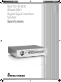
1
EX-IQ-BOX_K04_dat-sw_en_5214-2840-22_cover.indd 1 Data Sheet | 06.00 Test & Measurement R&S®EX-IQ-BOX (Model K04) Digital Signal Interface Module Specifications 11.05.2012 13:59:45 Version 06.00, May 2012 CONTENTS Definitions ....................................................................................................................................................................... 3 Introduction ..................................................................................................................................................................... 4 Key features .................................................................................................................................................................... 5 General concept of operation ........................................................................................................................................ 6 R&S®DigIConf digital interface configuration software ............................................................................................... 7 Test of DigRFSM modules ............................................................................................................................................... 8 Test of CPRI™ modules ............................................................................................................................................... 10 Overview of the Rohde & Schwarz instruments that work with the R&S®EX-IQ-BOX and list of the required options ........................................................................................................................................................................... 12 Signal interfaces ........................................................................................................................................................... 12 User-defined digital interface protocol ....................................................................................................................... 13 I/Q data .................................................................................................................................................................................................13 Clock .....................................................................................................................................................................................................13 DigRFSM digital interface protocol (R&S®EXBOX-B81/-K13 options)........................................................................ 14 CPRI™ digital interface protocol (R&S®EXBOX-B85/-K10/-K11 options) ................................................................. 17 Waveform memory (R&S®EXBOX-K90/-K91 options) ................................................................................................ 20 Recording memory (R&S®EXBOX-K94 option)........................................................................................................... 20 Digital standards with R&S®WinIQSIM2™ (for R&S®EXBOX-K90/-K91 options) ..................................................... 21 General data .................................................................................................................................................................. 22 Ordering information .................................................................................................................................................... 23 2 ® Rohde & Schwarz R&S EX-IQ-BOX (Model K04) Digital Signal Interface Module Version 06.00, May 2012 Definitions General Product data applies under the following conditions: • • • • Three hours storage at ambient temperature followed by 30 minutes warm-up operation Specified environmental conditions met Recommended calibration interval adhered to All internal automatic adjustments performed, if applicable Specifications with limits Represent warranted product performance by means of a range of values for the specified parameter. These specifications are marked with limiting symbols such as <, ≤, >, ≥, ±, or descriptions such as maximum, limit of, minimum. Compliance is ensured by testing or is derived from the design. Test limits are narrowed by guard bands to take into account measurement uncertainties, drift and aging, if applicable. Specifications without limits Represent warranted product performance for the specified parameter. These specifications are not specially marked and represent values with no or negligible deviations from the given value (e.g. dimensions or resolution of a setting parameter). Compliance is ensured by design. Typical data (typ.) Characterizes product performance by means of representative information for the given parameter. When marked with <, > or as a range, it represents the performance met by approximately 80 % of the instruments at production time. Otherwise, it represents the mean value. Nominal values (nom.) Characterize product performance by means of a representative value for the given parameter (e.g. nominal impedance). In contrast to typical data, a statistical evaluation does not take place and the parameter is not tested during production. Measured values (meas.) Characterize expected product performance by means of measurement results gained from individual samples. Uncertainties Represent limits of measurement uncertainty for a given measurand. Uncertainty is defined with a coverage factor of 2 and has been calculated in line with the rules of the Guide to the Expression of Uncertainty in Measurement (GUM), taking into account environmental conditions, aging, wear and tear. Device settings and GUI parameters are designated with the format “parameter: value”. Typical data as well as nominal and measured values are not warranted by Rohde & Schwarz. ® Rohde & Schwarz R&S EX-IQ-BOX (Model K04) Digital Signal Interface Module 3 Version 06.00, May 2012 Introduction ® The R&S EX-IQ-BOX is a digital signal interface module that provides flexible digital baseband inputs or outputs for Rohde & Schwarz signal generators, signal analyzers and communications testers. The main application field of this device is the conversion of digital I/Q signals of Rohde & Schwarz instruments into user-defined or standardized digital signal formats, and vice versa. ® For applications with user-defined protocols, the R&S EX-IQ-BOX enables either serial or parallel transmission of I/Q signals to a DUT, including variable clock modes, various data rates as well as different logical signal levels. The device under test is connected ® via adapter boards (= breakout boards) that are plugged directly into the R&S EX-IQ-BOX. ® In applications with standardized protocols, the R&S EX-IQ-BOX provides not only the I/Q data, but also control information of the ® respective standard. Equipped with the corresponding options, the R&S EX-IQ-BOX supports the standardized interface protocols SM CPRI™ (common public radio interface) as well as DigRF . Both define an interface for the transmission of I/Q and control data between baseband and RF module of a base station or mobile terminals respectively. ® The parameters can conveniently be set via the R&S DigIConf digital interface configuration software. ® When equipped with the R&S EX-IQ-BOX, a Rohde & Schwarz vector signal generator delivers realistic digital baseband signals for testing digital transceivers or other components. It can thus cover all common state-of-the-art standards such as LTE, WiMAX™ and ® 3GPP including HSPA, as well as user-defined signals and effects such as fading, AWGN or I/Q impairments. The R&S EX-IQ-BOX plus a Rohde & Schwarz signal analyzer enable the reliable analysis of digital baseband components. ® As an accessory for a Rohde & Schwarz communications tester, the R&S EX-IQ-BOX acts as a versatile digital baseband interface for signal generation and signal evaluation. “WiMAX Forum“ is a registered trademark of the WiMAX Forum. “WiMAX“, the WiMAX Forum logo, “WiMAX Forum Certified“, and the WiMAX Forum Certified logo are trademarks of the WiMAX Forum. ® CDMA2000 is a registered trademark of the Telecommunications Industry Association (TIA - USA). CPRI™ is a trademark of Nokia Siemens Networks. SM DigRF 4 is a trademark of MIPI. ® Rohde & Schwarz R&S EX-IQ-BOX (Model K04) Digital Signal Interface Module Version 06.00, May 2012 Key features • • • • • • Digital I/Q interface for signal generators, analyzers and communications testers from Rohde & Schwarz − Standard-compliant digital baseband signals − Signal generation for all important state-of-the-art standards such as EUTRA/LTE, 3GPP FDD, HSPA, WiMAX™, GSM/EDGE ® ® ® ® (together with the R&S SMU200A, R&S SMJ100A, R&S SMBV100A or R&S AMU200A) ® − Versatile signal processing functionalities including AWGN generation and I/Q impairments (together with the R&S SMU200A, ® ® ® R&S SMJ100A, R&S SMBV100A or R&S AMU200A) ® ® − Fading simulation (together with the R&S SMU200A, R&S AMU200A) ® − Simple and flexible conversion of digital baseband signals into analog IF or RF signals (together with the R&S SMU200A, ® ® R&S SMBV100A or R&S AMU200A) − Vector signal analysis of digital baseband signals of all important modern standards such as EUTRA/LTE, 3GPP FDD, HSPA, ® ® ® ® ® ® WiMAX™, GSM/EDGE (together with the R&S FSW, R&S FSQ, R&S FSG, R&S FSV, R&S FSVR or R&S FMU) − State-of-the-art test solution for wideband radiocommunications tests at the digital baseband interface of components ® (together with the R&S CMW500) Digital interface protocol “user-defined” − Flexible data formats o Maximum data rate of 100 MHz, variable resampling in conjunction with the Rohde & Schwarz instrument o Variable word size from 4 bit to 18 bit for I and Q o Parallel and serial formats o SDR and DDR data rates o Non-interleaved and I/Q and Q/I interleaved formats o Selectable bit order and word alignment o Two's complement and binary offset representation o Negate I and Q data o Positive and negative logic − Flexible clock generation o Maximum clock rate of up to 100 MHz for parallel formats and up to 400 MHz for serial formats o Internal and external clock reference o Selectable clock phase (90° steps) and skew (±5 ns) − Variable signal interface o LVTTL, CMOS (1.2 V, 1.5 V, 1.8 V, 2.5 V and 3.3 V) and LVDS logic standards o Two breakout boards included (single-ended, differential connectors) for connection of the device under test SM ® ® Digital interface protocol DigRF (with R&S EXBOX-B81 and R&S EXBOX-K13) SM ® − Test of DigRF 3G RFICs by means of R&S EXBOX-K13 option − Flexible hardware configuration and test case definition via freely configurable scripts − Hardware scheduler with timing resolution of 6.4 ns SM − PN16 and sine test signal generator for the physical layer DigRF signal SM ® − DigRF specific breakout board for interfacing with the DUT (R&S EXBOX-B81 option) SM o Support of DigRF 3G signals o Clock frequencies of 19.2/26/38.4/52 MHz o GPIO and GPIO group signals as well as SPI, I2C and RFFE buses for communications with external devices o Four user I/O BNC connectors with freely assignable function (trigger, marker, etc.) ® ® Digital interface protocol CPRI™ (with R&S EXBOX-B85 and R&S EXBOX-K10/-K11 options) ® − Test of CPRI™ radio equipment (RE) by means of R&S EXBOX-K10 option ® − Test of CPRI™ radio equipment control (REC) by means of R&S EXBOX-K11 option ® − Predefined interface settings for 3GPP FDD (incl. HSDPA, HSUPA, HSPA+), LTE, WiMAX™, CDMA2000 as well as userdefined configuration − Line bit rates of 1228.8 Mbit/s (= 2 ×), 2457.6 Mbit/s (= 4 ×) and 3072.0 Mbit/s (= 5 ×) − Flexible/packed antenna carrier (AxC) allocation with antenna carrier (AxC) grouping − Vendor-specific data − Control and management (C&M): fast C&M (realtime via Ethernet) and slow C&M (HDLC, realtime via RS-232) ® − CPRI™ specific breakout board for interfacing with the DUT (R&S EXBOX-B85 option) o Support of standard small form factor pluggable (SFP) modules for optical link o Additional SMA connectors for simultaneous monitoring of the CPRI™ output or for supply of the RX input signal SM Waveform playback and recording (for CPRI™ and DigRF ) ® ® − Direct playback from the R&S EX-IQ-BOX waveform memory (64 Msample) by means of the R&S EXBOX-K90 option ® − Multi-waveform playback for simultaneous output of up to four waveforms by means of the R&S EXBOX-K91 option ® − Support of R&S WinIQSIM2™ waveform creation software SM − Recording memory (512 Mbyte) for capturing of data that is received via the CPRI™ or DigRF link ® Easy interface configuration via enclosed R&S DigIConf software − Transient recorder for visual control of the generated digital signals (I/Q diagram, vector diagram, CCDF, spectrum) − Remote control of all parameters via LAN ® Rohde & Schwarz R&S EX-IQ-BOX (Model K04) Digital Signal Interface Module 5 Version 06.00, May 2012 General concept of operation ® The R&S EX-IQ-BOX digital signal interface module can be used in multiple ways. It either acts as an input interface to the DUT or as an output interface for data from the DUT. Signal generation and/or signal analysis are performed by the connected Rohde & Schwarz ® instrument that is used in conjunction with the R&S EX-IQ-BOX. ® Breakout boards are used to adapt the digital signal of the R&S EX-IQ-BOX to different physical digital interfaces (single-ended, ® differential, etc.). The use of user-designed breakout boards is also possible. The R&S EX-IQ-BOX digital interface module is ® configured via the enclosed R&S DigIConf software or directly via the controlling instrument (instrument-dependent). ® Configuration example: R&S EX-IQ-BOX as a signal output interface, ® ® ® directly controlled by a Rohde & Schwarz instrument (R&S SMU200A, R&S SMJ100A or R&S AMU200A). ® ® Configuration example: R&S EX-IQ-BOX as a signal output interface, controlled via the R&S DigIConf configuration software. ® ® Configuration example: R&S EX-IQ-BOX as a signal input interface, controlled via the R&S DigIConf configuration software. 6 ® Rohde & Schwarz R&S EX-IQ-BOX (Model K04) Digital Signal Interface Module Version 06.00, May 2012 R&S®DigIConf digital interface configuration software ® ® ® The R&S DigIConf controls the protocol, data, level and clock settings of the R&S EX-IQ-BOX. R&S DigIConf allows all interface ® settings to be selected independently of the connected Rohde & Schwarz instrument. Up to four R&S EX-IQ-BOX instruments can be ® controlled directly from the R&S DigIConf software. The program is to be installed on a PC running a Windows 2000/XP (Service Pack 2 required) or Windows 7 (32 bit/64 bit) operating system. ® ® R&S DigIConf digital interface configuration software; flexible control of up to four R&S EX-IQ-BOX instruments. ® Rohde & Schwarz R&S EX-IQ-BOX (Model K04) Digital Signal Interface Module 7 Version 06.00, May 2012 Test of DigRFSM modules ® ® ® Together with the R&S EXBOX-B81 and R&S EXBOX-K13 options, the R&S EX-IQ-BOX generates and receives signals in line with SM the DigRF digital interface protocol standard. The test solution allows physical layer verification of RF-ICs that communicate via SM ® SM DigRF 3G (by means of R&S EXBOX-K13). The device under test (DUT) is connected via the DigRF specific breakout board ® (R&S EXBOX-B81 option). Without the need for a fully functioning BB-IC, stand-alone RF-IC testing is made easy and the design cycle can be shortened. ® ® Flexible test setup control is provided by the R&S DigIConf configuration software: all relevant R&S Ex-IQ-BOX settings are SM ® accessible in a straight-forward manner. The chip at test is controlled via DigRF scripts that are first loaded to R&S DigIConf and ® SM compiled therein. Second, the compiled script is transferred to the R&S EX-IQ-BOX for execution. DigRF parameters as well as ® ® additional user data are also exchanged with the R&S EX-IQ-BOX via R&S DigIConf. I/Q waveform files (e.g. from ® TM ® ® R&S WinIQSIM2 or MATLAB ) can be loaded to the optional arbitrary memory (ARB) of the R&S EX-IQ-BOX, and recorded I/Q ® ® data can be read out from the optional recording memory of the R&S EX-IQ-BOX. Alternatively, the R&S EX-IQ-BOX can communicate with attached Rohde & Schwarz instruments via the Rohde & Schwarz digital I/Q interface. ® SM R&S EX-IQ-BOX, connectivity for DigRF . Further information on DigRF 8 SM can be found at www.mipi.org. ® Rohde & Schwarz R&S EX-IQ-BOX (Model K04) Digital Signal Interface Module Version 06.00, May 2012 SM Test setup example for full-duplex DigRF RF-IC test using ® ® ® ® ® R&S EX-IQ-BOX (with R&S EXBOX-B81 and R&S EXBOX-K13 options), R&S SMU200A and R&S FSQ. ® Rohde & Schwarz R&S EX-IQ-BOX (Model K04) Digital Signal Interface Module 9 Version 06.00, May 2012 Test of CPRI™ modules ® ® ® When equipped with the R&S EXBOX-B85 and R&S EXBOX-K10/-K11 options, the R&S EX-IQ-BOX generates and receives signals in line with the common public radio interface (CPRI™) protocol standard by converting the data accordingly. This enables the user to perform tests directly by using the CPRI™ interface between the base station radio equipment control (REC) and the base station radio equipment (RE). Straightforward connection to the device under test (DUT) is achieved via the CPRI™ ® ® specific breakout board (R&S EXBOX-B85 option). Both entities, the RE (by means of R&S EXBOX-K10) as well as the REC (by ® means of R&S EXBOX-K11) can be tested independently from each other. This helps to speed up time to market and to save valuable resources in research, development, verification and production. ® Easy CPRI™ interface configuration is ensured by the R&S DigIConf configuration software. All state-of-the-art standards such as ® 3GPP FDD (incl. HSDPA, HSUPA, HSPA+), LTE, WiMAX™, CDMA2000 and GSM/EDGE are supported as predefined interface settings. Additionally, the CPRI™ interface can be configured manually. The test solution provides individual uplink or downlink operation as well as full-duplex operation. Control and management information can be inserted in realtime. ® ® The R&S EX-IQ-BOX can also be equipped with an internal waveform memory option (R&S EXBOX-K90/-K91) that allows playback ® ® ® of precalculated waveforms (e.g. generated by R&S WinIQSIM2™ or MATLAB ). The R&S EXBOX-K91 option makes it possible to play back up to four waveforms at the same time. As a result, up to four different signals can be simultaneously transmitted via the same CPRI™ link (e.g. for multistandard, diversity or MIMO applications). ® ® A complementary recording memory option (R&S EXBOX-K94) captures the I/Q data that is received by the R&S EX-IQ-BOX via the CPRI™ link from the DUT. The received I/Q samples are stored in an internal memory of 512 Mbyte and are available for offline signal analysis and customer-specific post-processing by use of third-party tools. ® Furthermore – when combined with the Rohde & Schwarz signal generators and spectrum analyzers – the R&S EX-IQ-BOX is able to utilize the enhanced functions of the signal generators (e.g. digital communications standards, fading, AWGN, impairments) and the vast signal analysis features of the spectrum analyzers (e.g. ACP and EVM measurements for digital standards) even at the digital signal interface. The elaborate CPRI™ test solution from Rohde & Schwarz is a straightforward approach to test CPRI™ modules (RE and/or REC) and additionally offers the flexibility to tailor the test solution to customer needs. Further information on CPRI™ can be found at www.cpri.info. ® Configuration of the CPRI™ interface via the R&S DigIConf digital interface configuration software. 10 ® Rohde & Schwarz R&S EX-IQ-BOX (Model K04) Digital Signal Interface Module Version 06.00, May 2012 Test setup example for full-duplex CPRI™ radio equipment (RE) test ® ® ® ® ® using R&S EX-IQ-BOX (with R&S EXBOX-B85 and R&S EXBOX-K10 options), R&S SMU200A and R&S FSQ. Test setup example for full-duplex CPRI™ radio equipment control (REC) test ® ® ® ® ® using R&S EX-IQ-BOX (with R&S EXBOX-B85 and R&S EXBOX-K11 options), R&S SMU200A and R&S FSQ. ® Rohde & Schwarz R&S EX-IQ-BOX (Model K04) Digital Signal Interface Module 11 Version 06.00, May 2012 Overview of the Rohde & Schwarz instruments that work with the R&S®EX-IQ-BOX and list of the required options Rohde & Schwarz instrument Signal generators ® R&S AMU200A baseband signal generator and fading simulator ® R&S SMU200A vector signal generator ® R&S SMJ100A vector signal generator ® R&S SMBV100A vector signal generator Signal analysis ® R&S FSW signal and spectrum analyzer ® R&S FSQ signal analyzer ® R&S FSG signal analyzer ® R&S FMU36 baseband signal analyzer ® R&S FSV signal and spectrum analyzer Communications testers ® R&S CMW500 wideband radio communication tester Data recorders ® R&S IQR I/Q data recorder Digital I/Q input option ® 1 R&S AMU-B17 analog/digital baseband inputs ® R&S SMU-B17 analog/digital baseband inputs – ® R&S SMBV-K18 digital baseband connectivity Digital I/Q output option ® 2 R&S AMU-B18 digital baseband output ® R&S SMU-B18 digital baseband output ® R&S SMJ-B18 digital baseband output ® R&S SMBV-K18 digital baseband connectivity ® R&S FSW-B17 digital baseband interface ® R&S FSQ-B17 digital baseband interface ® R&S FSQ-B17 digital baseband interface ® R&S FSQ-B17 digital baseband interface ® R&S FSV-B17 digital baseband interface R&S CMW-B510A digital I/Q ® R&S CMW-B510A digital I/Q standard standard direction signals input, output bidirectional, dual 18-bit data buses for I and Q signals; two marker, trigger and auxiliary signals each 168-pin Tyco Z-Dok connects to breakout boards (included) with the following connector types: 2 × 50-pin dual 0.1 in header (single ended) 2 × 100-pin dual Samtec (LVDS) R&S FSW-B17 digital baseband interface ® R&S FSQ-B17 digital baseband interface ® R&S FSQ-B17 digital baseband interface ® R&S FSQ-B17 digital baseband interface ® R&S FSV-B17 digital baseband interface ® ® Signal interfaces User signal interface connector absolute maximum input level LVTTL, 3.3 V CMOS 1.2 V CMOS, 1.5 V CMOS, 1.8 V CMOS, 2.5 V CMOS LVDS interface for connecting the Rohde & Schwarz instrument Interface I/Q in, I/Q out logic level connector clock rate max. data rate –0.5 V, +3.8 V –0.5 V, Vcc + 0.4 V –0.5 V, +2.9 V Rohde & Schwarz digital I/Q Interface, I/Q data and control signals, data and 3 interface clock LVDS 26-pin MDR 66 MHz to 100 MHz clock rate 1 With two path-instruments that are equipped with a second digital baseband input option, a second R&S®EX-IQ-BOX can be connected. 2 With two path-instruments that are equipped with a second digital baseband output option, a second R&S®EX-IQ-BOX can be connected. 3 Rohde & Schwarz Digital I/Q Interface is a Rohde & Schwarz company standard for the transmission of digital I/Q data. It is supported by a wide range of instruments (signal generators, signal analyzers and communications testers). 12 ® Rohde & Schwarz R&S EX-IQ-BOX (Model K04) Digital Signal Interface Module Version 06.00, May 2012 User-defined digital interface protocol Enables the generation and reception of signals with user-defined protocols. I/Q data Format Serial format parallel, serial 0 to word size – 1 positive, negative 1 kHz to 100 MHz automatically performed by the Rohde & Schwarz instrument if required by the Rohde & Schwarz instrument I/Q, IF (complex) (clock rate)/4 two's complement, binary offset 4 bit to 18 bit (depending on the Rohde & Schwarz instrument) SDR, DDR 1, 4/5, 2/5, 1/5, 1/10, 1/20 none, I/Q, Q/I MSB, LSB MSB, LSB I, Q, I + Q positive, negative LVTTL, 1.2 V CMOS, 1.5 V CMOS, 1.8 V CMOS, 2.5 V CMOS, 3.3 V CMOS LVDS strobe position strobe polarity Sample rate Resampling I/Q impairments, I/Q swap Signal type IF frequency Numeric format Word size Data protocol Ratio of sample rate to clock rate Interleaving Word alignment Bit order Negate data Logic type Logic level single-ended differential Clock Clock rate Reference reference source, internal LVTTL/CMOS logic level LVDS logic level reference source, external LVTTL/CMOS logic level LVDS logic level source internal input impedance frequency Clock polarity Clock phase (relative to data) Clock skew (relative to data) level external user interface input frequency LVTTL/CMOS logic level LVDS logic level user interface range resolution ® 1 kHz to 100 MHz 1 kHz to 400 MHz 25 kHz to 100 MHz 25 kHz to 400 MHz internal (from Rohde & Schwarz instrument) external from user interface 50 Ω (nom.) 5 MHz, 10 MHz, 13 MHz (automatically selected) –3 dBm to 10 dBm 25 kHz to 100 MHz 25 kHz to 400 MHz positive, negative 0°, 90°, 180°, 270° –5 ns to +5 ns 50 ps Rohde & Schwarz R&S EX-IQ-BOX (Model K04) Digital Signal Interface Module 13 Version 06.00, May 2012 DigRFSM digital interface protocol (R&S®EXBOX-B81/-K13 options) ® SM Enables the R&S EX-IQ-BOX to generate and receive signals in line with the DigRF digital interface protocol standard. The ® SM ® SM R&S EXBOX-B81 (DigRF breakout board) option is a mandatory prerequisite for R&S EXBOX-K13 (DigRF 3G RF-IC test option). ® Only available for R&S EX-IQ-BOX with serial number > 102000. Applications Protocol version ® with R&S EXBOX-K13 option Operation script language script commands script parameter number size script memory user memory number size hardware scheduler number stages timing resolution commands I/Q payload input for streams I/Q payload output for streams marker number trigger source testing, diagnosis 14 ® Rohde & Schwarz R&S EX-IQ-BOX (Model K04) Digital Signal Interface Module simulation of BB-IC to test a RF-IC SM DigRF 3G 3.09.04 all frame types and payload sizes all line rates sleep mode hardware configuration and script ® operation via enclosed R&S DigIConf software; DigRF test cases can be covered via user-programmed scripts Pawn common Pawn script commands; ® R&S EX-IQ-BOX interface configuration (e.g. line rate, sleep mode); sending and receiving of control and data frames; sending and receiving of data frames via streams; 2 operation of GPIO, GPIO Group, SPI, I C and RFFE; operation of user memory (e.g. for boot or calibration data); operation of script parameter; operation of hardware scheduler (for timing critical sequences); wait, halt, resume 32 32 bit (each) 16 Mbyte 2 1 Mbyte (each) 2 512 (each) 6.4 ns GPIO out, send control frame, wait, send single frame with stream payload for one logical data channel can be input in realtime via the Rohde & Schwarz digital I/Q interface; PN16 via internal test generator; sine test generator; waveform memory ® (R&S EXBOX-K90/-K91 options) payload from one received logical data channel can be output in realtime via the Rohde & Schwarz digital I/Q interface; ® recording memory (R&S EXBOX-K94 option); payload tester 4 frame header (1 byte) and payload (3 byte) payload tester; status and error information Version 06.00, May 2012 SM ® DigRF breakout board (R&S EXBOX-B81 option) Clock RF-IC test: the breakout board generates an additional synchronous reference frequency for auxiliary equipment from the fed SysClk (RefClk) clock 1 SysClk (RefClk) direction input or output frequency 19.2/26/38.4/52 MHz level 1.1 V to 1.9 V output spectral purity integrated phase noise from 10 kHz –66 dBc (nom.) to 10 MHz noise floor density from 50 kHz to –140 dBc(1 Hz) (nom.) 10 MHz clock 2 reference signal output for auxiliary instruments, synchronous to SysClk (RefClk) direction output frequency 5/10 MHz level 1.1 V to 3.4 V connector SMA DigRF control DigRF control signals SM DigRF 3G signals SysClkEn, InterfaceEn level 1.1 V to 1.9 V connector ERNI SMC-1.27 mm, 50 pins (DigRF control) SM DigRF 3G the breakout board supports two TX data and RX data links TX number 2 (differential) line rates low speed (SysClk/4) high speed (312 Mbps) polarity normal, inverted differential impedance 100 Ω (nom.) return loss (≤ 156 MHz) –13 dB (nom.) TX 1 common mode offset 0.1 V to 1.5 V differential level 0.05 V to 0.4 V (Vpp) slew rate normal, slow shutdown mode yes TX 2 common mode offset 1.2 V (nom.) differential level 0.4 V (Vpp) (nom.) RX number 2 (differential) line rate low speed (SysClk/4) medium speed(SysClk) high speed (312 Mbps) polarity normal, inverted differential impedance 100 Ω (nom.) common mode voltage range 0.1 V to 3.2 V differential level range 0.1 V to 1 V (Vpp) connectors SMA ® Rohde & Schwarz R&S EX-IQ-BOX (Model K04) Digital Signal Interface Module 15 Version 06.00, May 2012 GPIO/GPIO group/SPI/I2C/RFFE User I/O 16 ® GPIO a 24 signals wide bidirectional bus as stimulus of proprietary interfaces direction input or output, individually configurable for each signal level 1.2 V to 3 V (nom.) connector ERNI SMC-1.27 mm, 50 pins (GPIO/SPI/I2C/RFFE)) GPIO group a 40 signals wide (5 groups with 8 signals each) bidirectional bus as stimulus of proprietary interfaces direction input or output, individually configurable for each group level 1.2 V to 3 V (nom.), individually configurable for each group connector ERNI SMC-1.27 mm, 50 pins (GPIO group) SPI SPI bus for communications with external devices signals SCLK, 2 MISO, 2 SS, 1 MOSI level 1.2 V to 3 V (nom.) connector ERNI SMC-1.27 mm, 50 pins (GPIO/SPI/I2C/RFFE) 2 IC I2C master for communication with external I2C devices signals SCL, SDA levels 1.2 V to 3 V (nom.) connector ERNI SMC-1.27 mm, 50 pins (GPIO/SPI/I2C/RFFE) RFFE RFFE master and slave busses for communications with RF front-end components (e.g. filters, converters, sensors) signals 2 × SCLK, 2 × SDATA levels 1.2 V to 1.8 V (nom.) connector ERNI SMC-1.27 mm, 50 pins (GPIO/SPI/I2C/RFFE) 4 bidirectional signals (2 groups with 2 signals each) with freely assignable operation (e.g. trigger, marker, user signals) direction input or output, individually configurable for each group level 3.3 V connectors BNC Rohde & Schwarz R&S EX-IQ-BOX (Model K04) Digital Signal Interface Module Version 06.00, May 2012 CPRI™ digital interface protocol (R&S®EXBOX-B85/-K10/-K11 options) ® Enables the R&S EX-IQ-BOX to generate and receive signals in line with the CPRI™ digital interface protocol standard. The ® ® R&S EXBOX-B85 (CPRI™ breakout board) option is a mandatory prerequisite for R&S EXBOX-K10 (CPRI™ RE test option) and/or ® ® R&S EXBOX-K11 (CPRI™ REC test option). Only available for R&S EX-IQ-BOX. Applications CPRI™ digital interface protocol Simulation mode Mobile standards CPRI™ basic frame configuration Link directions Signal definition simulation of radio equipment control (REC) to test a radio equipment (RE), simulation of radio equipment (RE) to test a radio equipment control (REC) in line with CPRI™ standard, version 4.0 ® with R&S EXBOX-K10 option REC (to test RE) ® with R&S EXBOX-K11 option RE (to test REC) 3G 3GPP FDD, 3GPP FDD HSDPA, 3GPP FDD HSUPA, 3GPP FDD HSPA+, ® CDMA2000 beyond 3G LTE, WiMAX™ uplink downlink signal = I/Q stream with settable sample rate to be mapped to AxC(s) number of configurable signals 1 to 4 (depending on configuration) ® I/Q payload input realtime via the R&S Digital I/Q Interface; PN16 via internal test generator; user-definable 20-bit pattern via internal test generator; waveform memory ® (R&S EXBOX-K90/-K91 options) I/Q payload output one selectable I/Q signal inside the received CPRI™ frame can be output in ® realtime via the R&S Digital I/Q Interface. recording memory ® (R&S EXBOX-K94 option) I/Q format two’s complement, 10-bit floating point format with common exponent (9E2) signal standard 3GPP FDD ® CDMA2000 LTE: 1.4/2.5/5/10/15/20 MHz WiMAX™: 3.5/5/7/8.75/10 MHz user-defined sample rate automatic in line with selected standard user-defined: 1 kHz to 100 MHz oversampling uplink 1, 2, 4 downlink 1, 2, 4 I/Q resolution uplink 4 bit to 18 bit downlink 4 bit to 18 bit AxC allocation packed word and bit address set automatically flexible user-definable word and bit address assigned AxCs full AxCs automatically assigned depending on signal data rate assigned data rate adaptation for nonvia user-definable AxC over time 3.84 MHz multiple signal data rates assignment configuration ® Rohde & Schwarz R&S EX-IQ-BOX (Model K04) Digital Signal Interface Module 17 Version 06.00, May 2012 Control and management (C&M) fast C&M slow C&M vendor-specific data layer 1 in band protocol ® with R&S EXBOX-K10 option TX RX ® with R&S EXBOX-K11 option RX framing Visualization Testing 18 ® Rohde & Schwarz R&S EX-IQ-BOX (Model K04) Digital Signal Interface Module Ethernet (realtime) via integrated terminal window in ® R&S DigIConf bit rates 240/480/960/1920/2400 kbit/s (depending on line bit rate); HDLC-coded data in realtime via RS-232 input and display of vendor data in line with CPRI™ version 4.0, figure 15 (illustration of subchannels in one hyperframe) generate RE Reset, SDI evaluate LOS, LOF, RAI, SDI evaluate LOS, LOF, RAI, SDI, RE Reset graphical display of CPRI™ basic frame configuration loopback mode low level BER measurement at physical layer Version 06.00, May 2012 ® CPRI™ breakout board (R&S EXBOX-B85 option) Connection of DUT Interfaces (general) small form factor pluggable (SFP) cage in line with multisource agreement (MSA), September 14, 2000 SFP cages SFP module SMA line bit rate TX interfaces RX interfaces Fast C&M Slow C&M General purpose input and output (GPIO) total jitter at 1228.8 MHz at 2457.6 MHz at 3072.0 MHz SMA connectors number logic type differential level coupling common mode offset differential impedance total jitter tolerance at 1228.8 MHz at 2457.6 MHz at 3072.0 MHz SMA connectors number logic type differential level coupling differential impedance return loss (at line bit rate) type connectors number rate type connectors number level application connectors number direction level ® via CPRI™ specific breakout board basic SFP control (LVCMOS) 2 enhanced SFP control (I C) module diagnostics 2 to be supplied by user simultaneous CPRI™ output for signal monitoring TX level adjustment RX equalizer simultaneous CPRI™ output for signal monitoring 2 × (= 1228.8 Mbit/s) 4 × (= 2457.6 Mbit/s) 5 × (= 3072.0 Mbit/s) (CPRI™ req. 0.35 SIpp) 0.07 SIpp (nom.) 0.14 SIpp (nom.) 0.16 SIpp (nom.) 1 (differential) CML (in line with XAUI) 0.1 V to 1.6 V (Vpp) DC 1.65 V (nom.) 100 Ω (nom.) 0.5 SIpp (nom.) 0.5 SIpp (nom.) 0.45 SIpp (nom.) 1 (differential) CML (in line with XAUI) > 100 mV (Vpp) AC 100 Ω (nom.) –12 dB (nom.) Ethernet RJ-45 1 10/100 Mbit/s HDLC DB9 1 LVCMOS 3.3 V marker output clock output BNC 3 output LVCMOS3.3 Rohde & Schwarz R&S EX-IQ-BOX (Model K04) Digital Signal Interface Module 19 Version 06.00, May 2012 Waveform memory (R&S®EXBOX-K90/-K91 options) ® ® ® Enables the use of I/Q waveforms (together with the R&S EXBOX-K10, R&S EXBOX-K11 or R&S EXBOX-K13 option). Waveforms ® can be generated by means of the R&S WinIQSIM2™ waveform creation software, for example. ® ® ® ® ® R&S EX-IQ-BOX and R&S EXBOX-B85 as well as R&S EXBOX-K10 or -K11 options or R&S EXBOX-B81 as well as R&S EXBOX-K13 option are required. Waveform memory size (shared by all active waveforms) resolution waveform length number of waveforms in parallel ® with R&S EXBOX-K90 option ® with R&S EXBOX-K90 and -K91 options setting ® with R&S EXBOX-K10/-K11 Sample rate ® with R&S EXBOX-K13 maximum rate for one active recording or waveform playback sum data rate for multiple active recordings and/or waveform playbacks 64 Msample 16 bit I and 16 bit Q (output resolution depending on application settings) 1 sample to 64 Msamples in one-sample steps 1 4 depending on the sample rate set in the option where the waveform is referenced controlled by RF-IC 100 Msample/s 160 Msample/s Recording memory (R&S®EXBOX-K94 option) ® SM Allows recording of the I/Q data that is received by the R&S EX-IQ-BOX via the CPRI™ or DigRF link from the DUT. With the SM DigRF link, data can also be recorded in raw mode. ® ® ® ® ® R&S EX-IQ-BOX and R&S EXBOX-B85 as well as R&S EXBOX-K10 or -K11 options or R&S EXBOX-B81 as well as R&S EXBOX-K13 option are required. Recording memory size (shared by all active recordings) recording mode ® with R&S EXBOX-K10/-K11 ® with R&S EXBOX-K13 number of recordings in parallel maximum data rate for one active recording or waveform playback sum data rate for multiple active recordings and/or waveform playbacks data length Recording mode I/Q samples resolution data rate settings ® with R&S EXBOX-K10/-K11 ® with R&S EXBOX-K13 data length Recording mode raw word size data rate settings ® with R&S EXBOX-K13 20 ® Rohde & Schwarz R&S EX-IQ-BOX (Model K04) Digital Signal Interface Module 512 Mbyte I/Q samples I/Q samples, raw data 2 100 Msample/s 160 Msample/s 1 sample to 128 Msample in one-sample steps 16 bit I and 16 bit Q (effective resolution depending on application settings) depending on the sample rate set in the option where the data is referenced controlled by RF-IC 1 word to 128 Mword in one-word steps 32 bit controlled by DigRF link settings Version 06.00, May 2012 Digital standards with R&S®WinIQSIM2™ (for R&S®EXBOX-K90/-K91 options) ® R&S WinIQSIM2™ requires an external PC. Standard GSM/EDGE EDGE Evolution 3GPP FDD 3GPP FDD enhanced BS/MS tests including HSDPA 3GPP FDD enhanced BS/MS tests including HSUPA ® CDMA2000 1xEV-DO IEEE 802.16 TD-SCDMA (3GPP TDD LCR) TD-SCDMA (3GPP TDD LCR) enhanced BS/MS tests including HSDPA IEEE 802.11n EUTRA/LTE HSPA+ EUTRA/LTE Release 9 and enhanced features IEEE 802.11ac Option ® R&S EXBOXK240 ® R&S EXBOXK241 ® R&S EXBOXK242 ® R&S EXBOXK243 ® R&S EXBOXK245 ® R&S EXBOXK246 ® R&S EXBOXK247 ® R&S EXBOXK249 ® R&S EXBOXK250 ® R&S EXBOXK251 ® R&S EXBOXK254 ® R&S EXBOXK255 ® R&S EXBOXK259 ® R&S EXBOXK284 ® R&S EXBOXK286 ® The options are described in the R&S WinIQSIM2™ data sheet (PD 5213.7460.22). ® Rohde & Schwarz R&S EX-IQ-BOX (Model K04) Digital Signal Interface Module 21 Version 06.00, May 2012 General data Power supply (included) EMC input voltage range, AC, nominal Environmental conditions operating temperature range storage temperature range climatic resistance Mechanical resistance vibration, sinusoidal vibration, random shock Electrical safety Approvals Dimensions (W × H × D) ® R&S EX-IQ-BOX ® R&S EXBOX-B81 breakout board ® R&S EXBOX-B85 breakout board ® Weight 4 R&S EX-IQ-BOX ® R&S EXBOX-B81 breakout board ® R&S EXBOX-B85 breakout board 100 V to 240 V (AC), 50 Hz to 60 Hz in line with EMC directive of EU (2004/108/EC), applied standard: EN 61326-1, EN 61326-2-1, EN 55011 (immunity for industrial environment, class 4 A emissions) +5 °C to +40 °C in line with EN 60068-2-1, EN 60068-2-2 −20 °C to +60 °C +40 °C/90 % rel. humidity in line with EN 60068-2-30 5 Hz to 150 Hz, max. 2 g at 55 Hz, const. 0.5 g at 55 Hz to 150 Hz, in line with EN 60068-2-6 10 Hz to 300 Hz, acceleration 1.2 g (RMS), in line with EN 60068-2-64 in line with MIL-STD-810E, method no. 516.4, procedure I, 40 g shock spectrum In line with IEC 61010-1, EN 61010-1, UL 61010-1, CAN/CSA-C22.2 No. 61010-1-04 VDE-GS, CCSAUS 198 mm × 47 mm × 190 mm (7.80 in × 1.85 in × 7.48 in) 205 mm × 37 mm × 195 mm (8.07 in × 1.46 in × 7.68 in) 190 mm × 37 mm × 135 mm (7.48 in × 1.46 in × 5.32 in) 1 kg (2.2 lb) 1 kg (2.2 lb) 1 kg (2.2 lb) The instrument complies with the emission requirements stipulated by EN 55011 class A. This means that the instrument is suitable for use in industrial environments. In line with EN61000-6-4, operation in residential, commercial and business areas or in small-size companies is not covered. Thus, the instrument may not be operated in residential, commercial and business areas or in small-size companies, unless additional measures are taken to ensure that EN 610000-6-3 is complied with. 22 ® Rohde & Schwarz R&S EX-IQ-BOX (Model K04) Digital Signal Interface Module Version 06.00, May 2012 Ordering information Designation Type Order No. ® Digital Signal Interface Module R&S EX-IQ-BOX 1409.5505K04 including power supply, 1 USB and 1 LVDS cable, 2 breakout boards, quick start guide, CD-ROM (with operating and service manual ® and R&S DigIConf software) Options ® CPRI™ Breakout Board R&S EXBOX-B85 1409.7208.02 ® CPRI™ RE Test R&S EXBOX-K10 1417.1170.02 ® CPRI™ REC Test R&S EXBOX-K11 1417.1186.02 SM ® DigRF Breakout Board R&S EXBOX-B81 1409.7008.02 SM ® DigRF 3G RF-IC Test R&S EXBOX-K13 1417.1192.02 ® Waveform Memory (64 Msample) R&S EXBOX-K90 1417.1005.02 ® Multiwaveform Playback R&S EXBOX-K91 1417.1011.02 ® Recording Memory (512 Mbyte) R&S EXBOX-K94 1417.1028.02 ® 5 Digital modulation systems using R&S WinIQSIM2™ ® GSM/EDGE R&S EXBOXK240 1417.1034.02 ® EDGE Evolution R&S EXBOXK241 1417.1040.02 ® 3GPP FDD R&S EXBOXK242 1417.1057.02 ® 3GPP FDD Enhanced BS/MS Tests including HSDPA R&S EXBOXK243 1417.1063.02 ® 3GPP FDD Enhanced BS/MS Tests including HSUPA R&S EXBOXK245 1417.1070.02 ® ® CDMA2000 R&S EXBOXK246 1417.1086.02 ® 1xEV-DO R&S EXBOXK247 1417.1092.02 ® IEEE 802.16 R&S EXBOXK249 1417.1111.02 ® TD-SCDMA (3GPP TDD LCR) R&S EXBOXK250 1417.1128.02 ® TD-SCDMA (3GPP TDD LCR) Enhanced BS/MS Tests R&S EXBOXK251 1417.1134.02 including HSDPA ® IEEE 802.11n R&S EXBOXK254 1417.1105.02 ® EUTRA/LTE R&S EXBOXK255 1417.1140.02 ® HSPA+ R&S EXBOXK259 1417.1157.02 ® EUTRA/LTE Release 9 and enhanced features R&S EXBOXK284 1417.1240.02 ® IEEE 802.11ac R&S EXBOXK286 1417.1263.02 Accessories ® User Signal Interface Adapter R&S EXBOX-Z1 1409.7437.02 (Tyco 128-pin Z-Dok adapter) ® Cadence Paladium Breakout Board R&S EXBOX-Z3 1417.3566.02 ® LVDS Cable for connecting digital baseband interfaces R&S SMU-Z6 1415.0201.02 Service options Extended Warranty, one year Extended Warranty, two years Extended Warranty, three years Extended Warranty, four years Extended Warranty with Calibration Coverage, one year Extended Warranty with Calibration Coverage, two years Extended Warranty with Calibration Coverage, three years Extended Warranty with Calibration Coverage, four years ® R&S WE1EX-IQ-BOX ® R&S WE2EX-IQ-BOX ® R&S WE3EX-IQ-BOX ® R&S WE4EX-IQ-BOX ® R&S CW1EX-IQ-BOX ® R&S CW2EX-IQ-BOX ® R&S CW3EX-IQ-BOX ® R&S CW4EX-IQ-BOX Please contact your local Rohde & Schwarz sales office. Extended warranty with a term of one to four years (WE1 to WE4) 6 Repairs carried out during the contract term are free of charge . Necessary calibration and adjustments carried out during repairs are also covered. Simply contact the forwarding agent we name; your product will be picked up free of charge and returned to you in top condition a couple of days later. Extended warranty with calibration (CW1 to CW4) Enhance your extended warranty by adding calibration coverage at a package price. This package ensures that your 6 Rohde & Schwarz product is regularly calibrated, inspected and maintained during the term of the contract. It includes all repairs and calibration at the recommended intervals as well as any calibration carried out during repairs or option upgrades. For product brochure, see PD 5213.9511.12 and www.rohde-schwarz.com 5 R&S®WinIQSIM2™ requires an external PC. 6 Excluding defects caused by incorrect operation or handling and force majeure. Wear-and-tear parts are not included. ® Rohde & Schwarz R&S EX-IQ-BOX (Model K04) Digital Signal Interface Module 23 Service you can rely on ❙ ❙ ❙ ❙ ❙ Worldwide Local and personalized Customized and flexible Uncompromising quality Long-term dependability About Rohde & Schwarz Rohde & Schwarz is an independent group of companies specializing in electronics. It is a leading supplier of solutions in the fields of test and measurement, broadcasting, radiomonitoring and radiolocation, as well as secure communications. Established more than 75 years ago, Rohde & Schwarz has a global presence and a dedicated service network in over 70 countries. Company headquarters are in Munich, Germany. Environmental commitment ❙❙ Energy-efficient products ❙❙ Continuous improvement in environmental sustainability ❙❙ ISO 14001-certified environmental management system Certified Quality System ISO 9001 Rohde & Schwarz GmbH & Co. KG www.rohde-schwarz.com Regional contact ❙❙ Europe, Africa, Middle East | +49 89 4129 12345 [email protected] ❙❙ North America | 1 888 TEST RSA (1 888 837 87 72) [email protected] ❙❙ Latin America | +1 410 910 79 88 [email protected] ❙❙ Asia/Pacific | +65 65 13 04 88 [email protected] ❙❙ China | +86 800 810 8228/+86 400 650 5896 [email protected] R&S® is a registered trademark of Rohde & Schwarz GmbH & Co. KG Trade names are trademarks of the owners | Printed in Germany (as) PD 5214.2840.22 | Version 06.00 | May 2012 | R&S®EX-IQ-BOX (Model K04) Subject to change © 2009 - 2012 Rohde & Schwarz GmbH & Co. KG | 81671 München, Germany 5214284022 EX-IQ-BOX_K04_dat-sw_en_5214-2840-22_cover.indd 2 11.05.2012 13:59:45