1
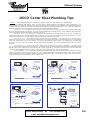
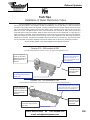
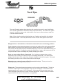
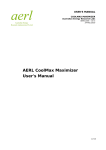
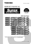
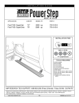
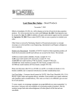
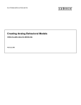
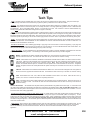
Exhaust Systems
Tech Tips
PAINT: All OSCO cast iron exhaust parts come with a coat of primer to protect them from flash rusting. This primer will accept
most enamel top coats and we recommend that you paint the parts to protect them from external corrosion.
GASKETS: The installer should remove all paint from the gasket surfaces before assembly of manifolds, risers, and elbows. Use
acetone or lacquer thinner to remove the paint. Do not scrape, sand, file, or use high speed rotary gasket removers. Gaskets should
be installed dry. Do not use gasket sealers, silicone, or compounds of any kind. Use of silicone or other so-called sealants may
actually cause gasket failure and water leakage into the engine or externally.
BOLTS: Do not use stainless steel or grade 2 bolts to install the risers or elbows. These bolts are too soft and will not hold a torque
setting, which can cause leaks at the gasket surface. Where bolts are specified, OSCO mounting kits use only grade 5, or better bolts.
Bolt torque should be reset after initial startup, while the engine is still warm. Refer to your original manufacturer's engine service
manual for specific torque settings. Never use anti-seize type products on bolts or studs. They will allow for loosening of the parts.
Studs: To prevent studs from backing out and causing leaks which can cause engine damage, use red thread locking compound.
Follow the manufacturers recommendations for their installation and removal. Do not use anti-sieze on bolts or studs as it is a
lubricant and will cause fastener to back out.
PIPE PLUGS AND FITTINGS: When installing pipe fittings or pipe plugs care must be taken to avoid over-tightening. Pipe plugs and
fittings are tapered and an overly tight pipe plug or fitting can crack the casting. Do not use thread sealants which contain Teflon. Do
not try to screw the plugs in flush with the casting, they only need to be snug.
GASKET PLACEMENT: In some applications the riser gasket alignment is critical. Improper installation of the gasket can cause the
engine to have an overheating concern. The following is a list of these gaskets and how they should be aligned:
M0002: Used between the 28001 manifold and the 29001 riser. Place the tab on the gasket to the front of the riser away
from the outlet end of the riser. This directs the water over the top of the riser for maximum cooling
CRR-G: Used between the CVCR818, CWCR818 and FLCR818 manifolds and the CRR-1 and CRR-3 risers and CRR14S spacer. Place the small rectangular hole of the gasket at the front of the riser, opposite the exhaust outlet end. This
directs the water over the top of the riser for maximum cooling. Note: When using the CRR-14S spacer, the gasket
between the manifold and the spacer is reversed so that the square hole is under the outlet end of the riser. The gasket
between the spacer and the riser is still placed with the square hole away from the outlet end of the riser, or to the front of
the riser
CRR-2-G: Used between the CSCR618 manifold and the CRR-2 riser. Place the small rectangular hole of the gasket at
the front of the riser, opposite the exhaust outlet end. This directs the water over the top of the riser for maximum cooling
6108: Used between the 7752, 7753, 7992 and 7993 manifolds and the 7169 or 7772 risers. Place the tab in the up
position, at 12 o’clock. This allows the water to completely fill the riser
6562: Used always at the elbow, either between the riser and elbow or the manifold and elbow. Place the tabs in the up
position, at 10 and 2 o'clock. This forces the water to fill the manifold and/or riser and flow over the top of the elbow for
maximum cooling
Stainless Steel Plates: All stainless block off plates must be placed between two gaskets of the same style. In most cases it will
not matter which gaskets are used because the water flow is stopped by the stainless plate. Note on 60207 Mercruiser Plate: This
plate has a small weep hole to allow trapped air to to be remove from the highest part of the log style Mercruiser manifolds. It can not
be used in fresh water cooling applications.
CLOSED COOLED SYSTEM ALSO KNOWN AS FRESH WATER COOLED: A closed cooled or fresh water cooled system is where anti-freeze is
recirculated through the engine only (called a Half-System) or through the engine and manifolds (called a Full-System). In both
systems the raw water or sea water exits through the riser and/or elbow. Some manifolds are unable to be fresh water cooled and
should remain on a Half-System. All In-Line 6 Cylinder manifolds should only be raw water cooled. They are designed to have
cool water running through them. Hot anti-freeze, plus the added temperature of the exhaust will cause them to become stressed and
crack from excessive heat.
KEEL COOLING: Keel Cooling is often installed incorrectly and can cause manifolds to crack internally from excessive heat. Do not
7
install OSCO manifolds into keel cooled systems that rely solely on the circulator pump with small diameter pipe for its circulation.
This is not satisfactory and will overheat the manifold. We do not recommend OSCO manifolds be used in any keel cooled
application.
Phone: 800-225-0004 Fax: 908-486-1056
e-mail: [email protected]
F53
Exhaust Systems
OSCO Center Riser Plumbing Tips
PLUMBING: The following plumbing tips cover the OSCO generic center riser style manifolds The diagram shows
one side only, plumb the other side the same. The correct way to plumb manifolds varies between engine manufacturers. You
should consult your engine manufacturer's service manual for the correct plumbing of your manifold. Generally speaking fill your
manifolds from the lowest point, and remove the water from the highest point (overboard through the riser, or through a fitting in the
manifold). Below are several typical ways to plumb an OSCO center riser style manifold:
“ONE HOSE” STYLE -- The water hose is connected to the manifold at its lowest point and water exits overboard through the
riser. All other tapped holes are plugged. Use an open gasket between the manifold and riser. Be sure that the small rectangular
hole in the gasket is opposite the exhaust outlet end of the riser.
“TWO HOSE” STYLE -- One water hose is connected to the manifold at its lowest point and one to the riser. All water exits
overboard through the riser. All other tapped holes are plugged. Use an open gasket between the manifold and the riser. Be sure
that the small rectangular hole in the gasket is opposite the exhaust outlet end of the riser.
“THREE HOSE” STYLE -- Recirculating system, preheats water in the manifolds -- Two water hoses are connected to the
manifold and one to the riser. Water enters the lowest point on the manifold and exits the manifold through a hose at the highest
point of the manifold (GM or Ford, see drawing). This water recirculates through the engine to be distributed by the thermostat
housing, to the risers and exits overboard. All other tapped holes are plugged. Use a block off gasket between the riser and the
manifold.
“THREE HOSE STYLE” -- Closed cooling or fresh water cooling, antifreeze in the engine and manifolds. -- Two water hoses
are connected to the manifold and one to the riser. Anti-freeze enters the lowest point on the manifold and exits the manifold
through a hose at the highest point of the manifold (GM or Ford, see drawing). Raw water enters the riser at the front and exits
overboard. All other tapped holes are plugged. Use a block off gasket between the riser and the manifold.
Spacer installation -- Use an open gasket between the spacer and the riser. Be sure that the small rectangular hole in the
gasket is opposite the exhaust outlet end of the riser. Use an open gasket between the manifold and the spacer. Be sure that the
small rectangular hole in the gasket is opposite of the one installed at the riser. This allows for water to flow through from the
manifold into the spacer and through the spacer into the riser.
One Hose Style
Two Hose Style
Water exits
overboard.
Water exits
overboard.
2
Water
passes
through at
the gasket.
Water enters
the riser at
the front and
through at
the gasket.
1
1
Water in at the lowest point.
Water in at the lowest point.
Spacer Installation
Three Hose Style
Water exits
overboard.
Water in 3
the riser
at the front.
Optional 2nd
water hose
inlet.
Ford
Water out at the
highest point.
2
2
GM
1
Water in at the lowest point.
i h
Water exits
overboard.
ll
i h
Water in at
the lowest
point.
7
1
d
Phone: 800-225-0004 Fax: 908-486-1056
e-mail: [email protected]
F54
Exhaust Systems
Tech Tips
Installation of Water Distribution Tubes
The water distribution tube is required when the engine sits on a steep angle. Its purpose is to remove
the air that gets trapped in the manifold, causing the manifolds to run hot and steam. It also increases the
circulation of the cooling water in the manifold. The tube is inserted from the exhaust outlet end and is almost as
long as the manifold itself. Neither tube has holes drilled in them. The #557 has two slots cut into one end, the
#424 has no slots. Do Not fill from the front of the manifold as this will send the water down the tube and
overboard without cooling the manifold. Block the water flow at the front of the manifold with a ¾" pipe plug or a
#106 front plate on the # 826. Fill the manifold from the lowest ¾" IPT port on the bottom rear inlet of the manifold.
Filling the manifold from the lowest point forces all air into the water distribution tube that would otherwise be
trapped in the manifold. This allows the manifold to stay full of water and to circulate fully. The water then flows
out of the manifold via the water distribution tube into the exhaust riser or elbow to be discharged overboard.
Do not modify gaskets. They are designed to allow proper water flow.
Chrysler 318 - 360 manifold # 826
( The #557 Water Distribution Tube is for use in raw water cooled applications only. )
Water exits from the manifold
through the water distribution
tube to the riser and / or
elbow to go overboard, forcing
out all trapped air.
All of the trapped air is
forced into the water
distribution tube at the
highest point in the
manifold.
#557 Copper Tube
is inserted from the
lowest end, inside
the manifold.
Water goes in at the bottom of
the manifold, filling from the
lowest point.
Chrysler 383 - 440 manifold # 7081
( The #424 Water Distribution Tube can be used in both raw and fresh water cooled applications. )
All of the trapped air is
forced into the water
distribution tube at the
highest point in the
manifold.
Water exits from the manifold through
the water distribution tube and is routed
by hose to the riser and / or elbow to go
overboard, forcing out all trapped air.
Water goes in at the bottom of
the manifold, filling from the
lowest point.
Phone: 800-225-0004 Fax: 908-486-1056
e-mail: [email protected]
#424 Copper Tube
is inserted from the
lowest end, inside
the manifold.
F55
Exhaust Systems
Tech Tips
480
open gasket
480-FW
blocked gasket
wrong
modified
CHRYSLER 318 - 360
Chrysler used only two styles of gasket for the 318 - 360, # 826 manifold. One blocks all water
from passing through it. This gasket is used to separate raw water and anti-freeze as well as to
allow water to flow out of the manifold from a fitting rather than through the gasket. The other
gasket has a 3/4” hole at the top to allow the raw water to flow out through the gasket to the riser
or elbow and go overboard. This gasket is used most commonly, and is the gasket used at the
fixed riser and elbow
Many installers look at the mating surface of the manifold, elbow and riser and see the water
passages in the parts. They incorrectly assume they got the wrong gasket and alter it to look like
the gasket surface. There is only one 3/4” hole at the top of the manifold to allow water to flow.
The rest of the gasket is blocked intentionally. This is correct. Do not modify the gasket. The one
hole in the top of the gasket is designed to allow the manifold to fill and remain full of water. By
cutting the gasket the manifold will not cool properly.
Tech tips for swivel exhaust
new style clamp
old style clamp
OSCO has improved the clamp used on the Chrysler swivel elbow and riser from the stamped style
on the right, to the cone shaped on the left. The cone may or may not touch on the lower elbow,
and may remain tilted as shown. The object is to pull the riser down on the O-rings to seal. Install
the O-rings with petroleum jelly, which will help avoid damaging the O-rings if the parts are moved
during assembly. The bolts and clamps only need to be snug, Do not over-tighten. Do not use
silicone or sealers on the O-rings. Remove paint from sealing surfaces using acetone or lacquer
thinner prior to installation.
Tech Tip applies to: 5639-CL, 7087-MK, 4-EXT-12 and 1812-8 are parts or kits which include the above clamps.
9234, 0402, 5639 and 4-EXT are parts which require these clamps for installation.
Phone: 800-225-0004 Fax: 908-486-1056
e-mail: [email protected]
F56
Exhaust Systems
Tech Tips
6562
6108
6562
CRUSADER
6108
s/s plate
7296
The round Crusader gaskets have tabs that stick up above the parts for easy identification.
The “one hole” gasket has 2 tabs and is always used at the elbow. The “three hole” gasket
has only 1 tab and is always used at the bottom of the risers to allow maximum water flow
to fill the manifold and riser.
Note: When using the stainless blocking plate use 2 gaskets and sandwich the stainless
plate between them. Since the plate blocks the flow of water either gasket can be used.
Misapplication or misinstallation of thermostat element will cause overheating problems.
Proper placement of the thermostat element is critical in the cooling of the engine and manifolds.
Many installers incorrectly put the element into the intake manifold, as in a car application. In
most cases, the thermostat should be installed under the top cover of the thermostat housing, not
into the intake manifold. If installed incorrectly the distribution of water to all components can be
compromised and cause overheating and possibly damage your engine.
Never run your engine without a thermostat. Yes, it makes your gauge show a cooler
temperature, but in reality your exhaust may be overheating dramatically. The thermostat is
designed to hold water in the engine long enough to dissipate heat from the engine. If the water
flows through too fast, it can not remove the heat from the engine.
Mercruiser uses a sleeve in some of their thermostat housings. These parts must be
installed properly or the engine may overheat.
Please note: Thermostat element temperatures vary from engine manufacturers. Typically a
raw-water cooled engine uses temperature ranges of 140-145 degees. Fresh-water cooled
engines typically use a range of 160-165 degrees. Most automotive thermostats range from
185-210 degrees and should not be used in marine applications. Always consult your marine
engine dealer for the correct thermostat for your application.
Phone: 800-225-0004 Fax: 908-486-1056
e-mail: [email protected]
F57
Exhaust Systems
Tech Tips
Typical Gasket Placement for Mercruiser Center Riser Manifolds with Spacer
using the following part numbers; 9745 / 7114B2 / 9011 Manifolds,
3320 / 3322 Spacers and 8503A / 4354 Risers.
RAW WATER COOLED MANIFOLDS
FRESH WATER COOLED MANIFOLDS
Sea Water In
Riser 4354 or 8503A (SHOWN)
Riser 8503A or 4354 (SHOWN)
Use the 8503-GR
(top) and the
8503-GO (bottom)
gaskets for a
standard cooling
system.
Spacer 3322 or
3320 (SHOWN)
Use the 8503-GO
(top) and the
8503-GB (bottom)
gaskets for a
closed cooled
system.
Sea water in
Spacer 3320 or
3322 (SHOWN)
Anti-Freeze out
Manifold 9745, 9011
or 7114B2 (SHOWN)
Manifold 9745, 7114B2
or 9011 (SHOWN)
Sea Water in
Anti-Freeze in
Phone: 800-225-0004 Fax: 908-486-1056
e-mail: [email protected]
F58