1
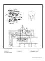
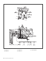
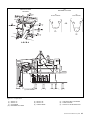
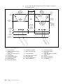
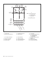
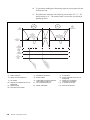
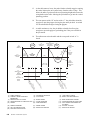
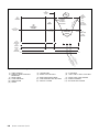
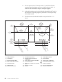
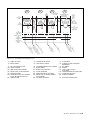
Contents
Section 4: Pinsetter Cycles ................................................................. 4-3
General Information ........................................................................ 4-3
Cycles .............................................................................................. 4-8
First Ball - Strike Cycle ....................................................... 4-8
First Ball - Standing Pins Cycle ........................................ 4-11
First Ball - Short Cycle ...................................................... 4-13
First Ball - Out-of-Range................................................... 4-15
First Ball - Foul ................................................................. 4-17
Second Ball - Single Detect ............................................... 4-19
Second Ball - Double Detect ............................................. 4-21
Second Ball - Out-of-Range .............................................. 4-23
Section 4: Pinsetter Cycles 4-1
Intentionally Blank Page
4-2
Section 4: Pinsetter Cycles
Section 4: Pinsetter Cycles
General Information
The GS Certified Pre-owned Pinsetter is capable of performing many different
cycles in reaction to a bowler throwing a ball. Before the pinsetter can begin
one of these cycles, The following events must occur:
1.
The pinsetter must be turned on, waiting for a ball.
2.
The following conditions must be met:
a.
b.
c.
d.
Table is up (“A” switch is closed)
Sweep is forward (“SM” switch is closed)
Sweep is up (“G” switch is not closed)
Spotting tongs are fully open (“ST” switch is closed)
To begin a cycle a bowler must throw a ball, the pinsetter reacts as follows:
1.
The ball detect “sees” a ball and sends a pulse to the Pinsetter CPU.
2.
The ball door solenoid energizes to lock the ball door for three seconds.
3.
The sweep release solenoid energizes dropping the sweep.
4.
Once sweep wagon lowers completely to the guarding position the “G”
switch closes.
5.
The table motor runs counterclockwise to start the cycle, causing the
switch cluster cam to leave the A switch and rotate toward the “B”
switch.
Every cycle can be divided into three segments Refer to Figure 4-1. The first
segment is the detection stroke of the cycle. Figure 4-2. In this segment, the
table is lowered to detect or find out the results of the ball hitting the pins. The
sweep segment occurs after the table is raised, during this segment the sweep
clears all the deadwood from the pin deck and flat gutters. Figure 4-3. The final
segment is the preparation stroke in which the pinsetter readies itself for the
next ball. This may be a short stroke where pins are respotted back onto the pin
deck if they were lifted by the table during the detection segment or it may be a
long stroke where new pins are set on the pin deck in preparation for a new
frame. Figure 4-4.
Section 4: Pinsetter Cycles 4-3
A
(1)
(2)
(3)
(4)
(5)
(6)
(7)
DETECTION
SWEEP
PREPARATION
COUNTERCLOCKWISE
CLOCKWISE
STANDING PIN HEIGHT
NEW PIN SETTING HEIGHT
A
Section 4: Pinsetter Cycles
A
A
(6)
STANDING PIN
HEIGHT
(6)
STANDING PIN
HEIGHT
B C D
(4)
CCW
Figure 4-1. Cycle Segments
4-4
(3)
PREPARATION
(2)
SWEEP
(1)
DETECTION
D C B
(2)
SWEEP
(5)
CW
(7)
NEW PIN
SETTING HEIGHT
(6)
MOVEMENT OF TABLE
A
A
B C D
(7)
CCW
ABCDA
Figure 4-2. Detection Stroke
(1) SWITCH “C”
(2) SWITCH “B”
(3)
(4) SWITCH “A”
(7) COUNTERCLOCKWISE
(5) SWITCH “D”
(6)
CAM ROTATING COUNTER
CLOCKWISE
MOVEMENT OF TABLE
Section 4: Pinsetter Cycles 4-5
Figure 4-3. Sweeping Deadwood.
(1) SWITCH “C”
(4) SWITCH “A”
4-6
Section 4: Pinsetter Cycles
(2) SWITCH “B”
(5) SWITCH “D”
(3)
CAM STOPPED
(9)
SWITCH CLUSTER
ROTATION
(10)
MOVEMENT OF TABLE
(8)
LONG STROKE
(6)
SHORT STROKE
A
A
A
A
OR
OR
D C B
B
D
C
(7)
CW
(7)
CW
ADCBA
(8) LONG STROKE
Figure 4-4. Preparation
(1)
(4)
(7)
(10)
SWITCH “C”
SWITCH “A”
CLOCKWISE
MOVEMENT OF TABLE
(2) SWITCH “B”
(5) SWITCH “D”
(8) LONG STROKE
(3)
(6)
(9)
CAM ROTATING CLOCKWISE
SHORT STROKE
SWITCH CLUSTER ROTATION
Section 4: Pinsetter Cycles 4-7
Cycles
There are five first ball cycles and three second ball cycles. Additional cycles
are available if a scoring system is connected to the pinsetters.
The first ball cycles are:
1.
2.
3.
4.
5.
First Ball - Strike
First Ball - Standing Pins
First Ball - Short Cycle
First Ball - Out-Of-Range
First Ball - Foul
The second ball cycles are:
1.
2.
3.
Second Ball - Single Detect
Second Ball - Double Detect
Second Ball - Out-Of-Range
First Ball - Strike Cycle
A strike cycle results when a bowler is successful in knocking down all the pins
with the first ball. The pinsetter will sweep any deadwood into the pit and set
ten new pins onto the pin deck. The following is a complete description of this
cycle. Refer to Figure 4-5.
4-8
Section 4: Pinsetter Cycles
1.
A ball detect occurs.
2.
In response to the ball detect signal the sweep release solenoid energizes
to lower the sweep into the guard position actuating switch “G”. The
ball door solenoid energizes, locking the ball door for three seconds.
3.
The table motor runs counterclockwise. The cam on the table shaft will
leave switch “A” moving toward switch “B”.
4.
As the table lowers “OOR” switch closes to indicate the table entered
the detection area.
5.
The table will make a short stroke as it stops on the stroke limiter plate.
6.
At switch “B”, the Pinsetter CPU reads the pin holder switches and
determines that no pins were left standing. The Pinsetter CPU sends
pinfall information (a strike) to the automatic scorer (if installed).
7.
The cam passes switch “C” with no action.
8.
As the cam actuates switch “D”, the pin holder solenoids energize to
open the grippers.
9.
As the table is lifted to its raised position, the open grippers push up on
the pin release levers, causing pins to drop into the pin holders. Actuation of the pin holder switch by the pin causes the solenoid to deenergize, closing the gripper. Actuation of switch “A” caused the table
motor to turn off.
10.
The sweep motor turns on, pulling the sweep back then forward to clear
the deadwood. When the sweep wagon is fully forward once again,
switch “SM” closes causing sweep motor to turn off.
11.
The table motor runs clockwise and the cam leaves the switch “A” and
travels to switch “D.”
12.
As the table starts to lower, the stroke limiter solenoid is energized
causing the stroke limiter plate to be pulled away from the T-stop. This
allows the table to go down to the pin deck, and releases the swing
shafts on the table allowing the pin holders to go into the vertical
pinsetting position.
13.
The cam passes switch “D” and at switch “C” pin holder solenoids
energize to open the grippers and leave the pins on the pin deck. At
switch “B” the solenoids de-energize, closing the grippers.
14.
As the table continues to rise, the pin holder solenoids for the 7 and 10
pins energizes to open the grippers to preload the 7 and 10 pins if they
are in the pin station.
15.
The table motor raises the table and the sweep until switch “A” is
closed.
Section 4: Pinsetter Cycles 4-9
16.
At “A” switch, the table motor turns off. The pinsetter is ready for a
new first ball cycle.
(2)
(1)
TABLE
HOME/UP
(22)
DETECTION
HEIGHT
(18)
CLUSTER
SWITCHES A
(21)
(3)
LOAD PINS
IN TABLE
CCW
(17)
OOR
SWITCH
(10
)
SW RAIS
EE E
P
(4)
STROKE LIMITER
SOLENOID
ENERGIZED
(12)
SWEEP
(16)
DETECTION
STROKE
(5)
READY
FOR
FIRST
BALL
CW
(6)
LOAD 7 AND
10 PIN
IF AVAILABLE
(11)
NEW
PINSETTING
STROKE
C
B
A
D
(19)
G
SWEEP
DOWN
(20)
SWEEP SM
FORWARD
(13)
CLEARING
DEADWOOD
A
D
C
B
(7)
OPEN 7 AND 10
GRIPPER
TO PRELOAD
7 AND 10 PIN
A
G
SM
SM
SM
(23)
ST
SPOTTING
TONG SWITCH
ST
N
GR
PI
IP
RS
S
ER
LD
PE
HO
RS
PE
IP
GR
E
RS
OS
PE
CL
IP S
(8)
GR PIN
EN ET
OP O S
T
D
EA
)R
N
PE
) O
(9)
(14
(15
Figure 4-5. First Ball Strike Cycle.
(1) TABLE HOME/UP
(4) STROKE LIMITER SOLENOID
ENERGIZED
(7) OPEN 7 AND 10 GRIPPER TO
PRELOAD
(10) RAISE SWEEP
(13) CLEARING DEADWOOD
(16) DETECTION STROKE
(19) SWEEP DOWN
(22) DETECTION HEIGHT
4-10
Section 4: Pinsetter Cycles
(2) COUNTERCLOCKWISE
(5) READY FOR FIRST BALL
(3)
(6)
(8) CLOSE GRIPPERS
(9)
(11)
(14)
(17)
(20)
NEW PINSETTING STROKE
OPEN GRIPPERS
OUT-OF-RANGE SWITCH
SWEEP FORWARD
(12)
(15)
(18)
(21)
LOAD PINS IN TABLE
LOAD 7 AND 10 PIN IF
AVAILABLE
OPEN GRIPPERS TO SET PINS
7 AND 10 PIN
SWEEP
READ PIN HOLDERS
CLUSTER SWITCHES
CLOCKWISE
First Ball - Standing Pins Cycle
This cycle results when the bowler knocks down up to nine pins. During this
cycle the pinsetter lifts the pins left standing on the pin deck, the sweep clears
the deadwood into the pit and the pins are set back down on the pin deck. The
following is a description of this cycle. Figure 4-6.
1.
A ball detect occurs.
2.
In response to the ball detect signal the sweep release solenoid energizes
to lower the sweep into the guard position actuating switch “G”. The
ball door solenoid energizes, locking the ball door for three seconds.
3.
The table motor runs counterclockwise. The cam on the table shaft will
leave switch “A” moving toward switch “B”.
4.
As the table lowers “OOR” switch closes to indicate the table entered
the detection area.
5.
The table will make a short stroke as it stops on the stroke limiter plate.
6.
At switch “B” the Pinsetter CPU will read the pinholder switches and
determine one or more pins are standing. The CPU sends the pinfall
information to the automatic scorer (if installed).
The spotting tong solenoid will energize and the tongs will be driven
closed.
7.
The cam passes switch “C” with no action.
8.
As the cam actuates switch “D” the spotting tong solenoid is de-energized to stop the spotting tongs from closing further.
9.
The table rises with the pins in the tongs. The table motor turns off
when switch “A” is closed.
10.
The sweep motor turns on, pulling the sweep back then forward to clear
the deadwood. When the sweep wagon is fully forward once again, the
“SM” switch closes causing the sweep motor to turned off.
11.
The table motor runs clockwise and the cam leaves switch “A” and
travels to switch “D”.
12.
When switch “D” is closed, the spotting tong solenoid is energized.
Because the table motor is now turning clockwise, the tongs will open
leaving the pins on the pin deck.
Section 4: Pinsetter Cycles 4-11
13.
The Cam passes switch “C” with no action.
14.
At switch “B” the spotting tong solenoid de-energizes to stop the tong
from opening further. The pin holder solenoids will energize to open the
grippers allowing ten pins to be loaded when the table returns to home
position.
15.
The sweep release chain raises the sweep.
16.
The table motor shuts off when switch ”A” is actuated.
17.
The pinsetter is ready for a second ball cycle.
(3)
(2)
CW
CCW
(22)
DETECTION HEIGHT
(4)
READY FOR
SECOND
BALL
R (8
SW AIS )
EE E
P
(1)
TABLE
HOME
(10)
PIN
(10)
PIN
(13)
CLEARING
DEADWOOD
(16)
CLOSE
TONGS
B
C
D
(5)
LOAD 10 PINS
IF AVAILABLE
(9)
RESPOTTING
STROKE
(11)
REOPEN
TONGS
A
A
SM
SM
D
C
B
A
G
SM
ST
G ZES S)
ON I
(6) T ERG ONG
G N T
S
TIN E-E G
OT D NIN ER
SP ID PE IPP
NO O GR
LE RE
N
SO OP PE
G S
O
T
(S
ON ZE
(7) T GI
G ER
TIN EN ING
OT
D
I
EN
SP NO OP GS)
LE (RE ON
T
SO
G ZES
)
ON GI S)
(14 G T ER NG
N O
TIN E-E T
OT D ING
SP ID S
NO LO
ID
LE P C
RS NO )
SO TO
) LDE LE GS
(S
(15 HO SO TON
S
N
PI NG ING
O S
AD T LO
RE ING (C
T
D
OT GE
SP GA
EN
(19)
SWITCH
CLUSTER A
(20)
G
SWEEP
SWITCH SM
ST
(21)
SPOTTING
TONG
SWITCH
(12)
SWEEP
(17)
DETECTION
STROKE
(18)
OOR
SWITCH
Figure 4-6. First Ball Standing Pins Cycle.
(1) TABLE HOME
(4) READY FOR SECOND BALL
(7) SPOTTING TONG SOLENOID
ENERGIZES (REOPENING TONGS)
(10) PIN
(13) CLEARING DEADWOOD
(16) CLOSE TONGS
(19) SWITCH CLUSTER
(22) DETECTION HEIGHT
4-12
Section 4: Pinsetter Cycles
(2) COUNTERCLOCKWISE
(5) LOAD 10 PINS IF AVAILABLE
(3)
(6)
(8) RAISE SWEEP
(9)
(11) REOPEN TONGS
(14) SPOTTING TONG SOLENOID
DE-ENERGIZES (STOP CLOSING
TONGS)
(17) DETECTION STROKE
(20) SWEEP SWITCH
(12)
(15)
(18)
(21)
CLOCKWISE
SPOTTING TONG SOLENOID
DE-ENERGIZES (STOP
REOPENING TONGS) OPEN
GRIPPERS
RESPOTTING STROKE
SWEEP
READ PIN HOLDERS SPOTTING
TONG SOLENOID ENGAGED
(CLOSING TONGS)
OUT-OF-RANGE SWITCH
SPOTTING TONG SWITCH
First Ball - Short Cycle
A short cycle occurs in the following situations after rolling the first ball.
A.
B.
C.
The 7 pin was the only pin knocked down by a ball.
The 10 pin was the only pin knocked down by a ball.
No pins were knocked down by a ball (gutter ball).
If one of these conditions occurs, the Pinsetter CPU determines that there is no
deadwood and the sweep operation is not necessary. The table lowers on top of
the pins and then returns to the home position. Decreasing the length of time
necessary to complete the first ball cycle. Refer to Figure 4-7.
1.
A ball detect occurs.
2.
The sweep release solenoid energizes to lower the sweep into the guard
position actuating the “G” switch. The ball door solenoid energizes
locking the ball door for three seconds.
3.
The table motor runs counterclockwise to allow the table to lower. The
cam on the table shaft will leave switch “A.”
4.
The table racks will lower and pulse (close) the “OOR” switch indicating the table entered the detection area.
5.
The table will make a short stroke as it stops on the stroke limiter plate.
6.
At the “B” switch, the Pinsetter CPU will read the pin holder switches
and find one of the three conditions listed above. It also sends the
pinfall information to the automatic scorer.
7.
The table motor will stop briefly when the “C” switch is closed. Then
reverse direction (CW).
8.
The pin holder solenoids energize to open the grippers at switch “B” to
allow pins to be loaded when the table returns to the home position.
9.
The sweep release chain raises the sweep.
10.
The table motor shuts off when “A” switch is actuated.
Section 4: Pinsetter Cycles 4-13
(3)
(2)
(15)
DETECTION
STROKE
(14)
OOR
SWITCH
(17)
DETECTOR
HEIGHT
RA
IS (16
E
)
SW
EE
P
(1)
TABLE
HOME
(4)
READY
FOR
SECOND
BALL
CW
CCW
(5)
PRELOAD
PINS
(6)
NOTE: RESULTS BECAUSE OF
A. 7 PIN DOWN ONLY
B. 10 PIN DOWN ONLY
C. GUTTER BALL
(7)
(13)
SWITCH
CLUSTER
(12)
SWEEP
DOWN
(11)
SWEEP
FORWARD
A
B
C
B
A
G
G
SM
SM
(18)
SPOTTING TONGS ST
OPEN
ST
NO SWEEP NECESSARY
S
ER
(8) IPP
GR
EN
OP
E
RS
(9) VE R
RE TO
& MO
RS
OP LE )
DE
ST TAB (10 HOL
N
PI
AD
RE
Figure 4-6. First Ball Short Cycle.
(1) TABLE HOME
(4) READY FOR SECOND BALL
(2) COUNTERCLOCKWISE
(5) PRELOAD PINS
(3)
(6)
(7) NO SWEEP NECESSARY
(8) OPEN GRIPPERS
(9)
(10) READ PIN HOLDERS
(13) SWITCH CLUSTER
(16) RAISE SWEEP
4-14
Section 4: Pinsetter Cycles
(11) SWEEP FORWARD
(14) OUT-OF-RANGE SWITCH
(17) DETECTOR HEIGHT
(12)
(15)
(18)
CLOCKWISE
NOTE: RESULTS BECAUSE OF
A. 7 PIN DOWN ONLY
B. 10 PIN DOWN ONLY
C. GUTTER BALL
STOP AND REVERSE TABLE
MOTOR
SWEEP DOWN
DETECTION STROKE
SPOTTING TONG OPEN
First Ball - Out-of-Range
During the course of bowling, a ball may strike the pins in such a way that a pin
slides out of its normal position but does not fall down. If the pin moves far
enough, the bottom of the table will lower on top of the pin. This will keep the
table from lowering to the normal detection height and prevent it from detecting
the standing pins and thus scoring or picking them up. Bowling Association
rules (such as ABC and FIQ) require that any deadwood left on the lane surface
be removed before the bowler rolls a second ball. To accomplish this, the
Pinsetter CPU will stop the pinsetter after the detection portion of the cycle and
signal for the mechanic/technician to remove any deadwood and to restart the
pinsetter. Refer to Figure 4-8. The cycle occurs as follows:
1.
A ball detect occurs.
2.
In response to the ball detect signal the sweep release solenoid energizes
to lower the sweep into the guard position actuating switch “G”. The
ball door solenoid energizes, locking the ball door for three seconds.
3.
The table motor runs counterclockwise. The cam on the table shaft will
leave switch “A” moving toward switch “B”.
4.
The table lowers on top of the off spot pin stopping the table before it
can close the “OOR” switch.
5.
At switch “B” the Pinsetter CPU will ignore the pin holder switches,
because the “OOR” switch had not been actuated. The pinfall will have
to be entered manually if scorers are present.
6.
The table motor continues to turn the cam past switches “C” and “D”
switches until switch “A” is closed.
7.
The pinsetter will shut off at “A” switch with the sweep still down in
the guarding position. The trouble light will flash and the LED will
display the error code “PO.”
8.
To clear the error, the mechanic must turn the stop/run switch on the
Nexgen box or mechanic’s rear control box “OFF”. Deadwood can then
be cleared from the pin deck.
9.
The mechanic must then turn the pinsetter back on to allow the pinsetter
to resume operation. (If Frameworx , Classic or Vector scoring is
involved, a score correction must be made at the scorer console before
the pinsetter can restart).
Section 4: Pinsetter Cycles 4-15
10.
To prevent the standing pins from being swept, the sweep motor will not
be allowed to run.
11.
The table motor rotates the cam clockwise past switches “D”, “C”, “B”
until it returns to “A.” The reason for this is to raise the sweep from its
guarding position.
(2)
(3)
CCW
EE
(11)
OOR
SWITCH
(12)
CLUSTER
SWITCHES A
B
C
(6)
SHORT STROKE
ONTO "OOR" PIN
(7)
NO
SWEEP
D
A
A
D
C
B
(13)
SWEEP
G
DOWN
(14)
SWEEP
FORWARD SM
(16)
SPOTTING
TONG
OPEN
RA
IS (5)
E
SW
(10)
DETECTION
STROKE
ON "OOR" PIN
(15)
DETECTION
HEIGHT
(4)
READY
FOR
SECOND BALL
CW
P
(1)
TABLE
HOME/UP
A
G
SM
ST
ST
R
(9) OO LDE
E O
NS N H
SE PI
RE
NO
RS
P
TO HT
(8) R S LIG "
TE LE "PO
ET UB DE
NS O
PI TR R CO
D O
RE RR
E
IG
Figure 4-8. First Ball Out-Of-Range Cycle.
(1) TABLE HOME/UP
(4) READY FOR SECOND BALL
(7) NO SWEEP
(10) DETECTION STROKE ON OUT-OFRANGE PIN
(13) SWEEP DOWN
(16) SPOTTING TONG OPEN
4-16
Section 4: Pinsetter Cycles
(2) COUNTERCLOCKWISE
(5) RAISE SWEEP
(3)
(6)
(8) PINSETTER STOP RED TROUBLE
LIGHT ERROR CODE “PO”
(11) OUT-OF-RANGE SWITCH
(12)
CLOCKWISE
SHORT STROKE ONTO OUT-OFRANGE PIN
SENSE OUT-OF-RANGE
IGNORE PIN HOLDERS
CLUSTER SWITCHES
(14) SWEEP FORWARD
(15)
DETECTION HEIGHT
(9)
First Ball - Foul
When a bowler steps on the foul line, a beam of light over the foul line is
interrupted. A signal is then sent to the Pinsetter CPU. The pinsetter must
sweep all pins and set ten new pins. The bowler receives zero pins for the first
ball and has only one chance to knock down the new pins. Refer to Figure 4-9.
1.
A foul signal is sent to the Pinsetter CPU.
2.
A ball detect occurs.
3.
In response to the ball detect signal the sweep release solenoid energizes
to lower the sweep into the guard position actuating switch “G”. The
ball door solenoid energizes, locking the ball door for three seconds.
4.
The table motor runs counterclockwise. The cam on the table shaft will
leave switch “A” moving toward switch “B”.
5.
As the table lowers “OOR” switch closes to indicate the table entered
the detection area.
6.
The table will make a short stroke as it stops on the stroke limiter plate.
7.
At switch “B”, the Pinsetter CPU will ignore the pin holder switches. A
foul signal will be sent to the automatic scorer (if installed) instead of
the actual pinfall.
8.
The cam passes switch “C” with no action.
9.
As the cam actuates switch “D”, the pin holder solenoids for all 10 pins
energize to open the grippers.
10.
As the table returns to its home position the open grippers push up on
pin release levers, dropping the pins into the pin holders. Once the pin
holder’s switch has been closed, the solenoid de-energized closing the
gripper at switch “A” the table motor shuts off.
11.
The sweep motor turns on, pulling the sweep back then forward to clear
the pin deck. When the sweep wagon is fully forward once again,
switch “SM” closes causing the sweep motor to be turned off.
12.
The table motor runs clockwise rotating the cam from switch “A” to
switch “D.”
Section 4: Pinsetter Cycles 4-17
13.
As the table starts to lower, the stroke limiter solenoid energizes causing
the stroke limiter plate to be pulled away from the tables T-Stop. This
allows the table to go down to the new pinsetting height and releases the
swing shafts on the table allowing the pin holders to go into the vertical
pinsetting position.
14.
The cam passes switch “D” and at switch “C” the pin holder solenoids
energize to open the grippers leaving the pins on the pin deck. At switch
“B” the solenoids de-energize closing the grippers.
15.
As table continues to rise, the pin holder solenoids for all ten pins
energizes to open the grippers; preloading pins if they are available in
the pin station.
16.
The table motor raises the table and the sweep until switch “A” is
closed.
(3)
LOAD PINS
IN TABLE
(2)
CCW
(6)
READY
FOR SECOND
BALL
(5)
CW
EP
(1)
TABLE
HOME/UP
(4)
STROKE LIMITER
SOLENOID
ENERGIZED
(18)
SWITCH
CLUSTER
ISE (8)
SW
E
RA
(20)
DETECTION
STROKE
(19)
OOR
SWITCH
(21)
DETECTION
HEIGHT
(7)
PRELOAD
PINS TO
TABLE
(13)
SWEEP
(9)
NEW
PINSETTING
STROKE
(10)
OPEN
GRIPPERS
TO PRELOAD
PINS
A
B
C
D
A
A
D
C
B
(17)
SWEEP DOWN G
A
G
(16)
SWEEP
FORWARD SM
SM
SM
SM
(22)
SPOTTING ST
TONGS
OPEN
ST
RS
) PE
(11 RIP
G
E
RS
OS 12) PE S
( IP IN
CL
GR W P
EN NE
OP ET
S
RS
E
4)
(1 IPP
GR
EN
OP
R S
TO ER
5)
(1 TEC LD
O
DE H
UL PIN
FO RE
NO
IG
Figure 4-9. First Ball Foul Cycle.
(1) TABLE HOME/UP
(2)
(4) STROKE LIMITER SOLENOID
(5)
ENERGIZED
(7) PRELOAD PINS TO TABLE
(8)
(10) OPEN GRIPPERS TO PRELOAD PINS (11)
(13) SWEEP
(14)
(16) SWEEP FORWARD
(19) OUT-OF-RANGE SWITCH
(22) SPOTTING TONGS OPEN
4-18
Section 4: Pinsetter Cycles
COUNTERCLOCKWISE
CLOCKWISE
RAISE SWEEP
CLOSE GRIPPERS
OPEN GRIPPERS
(17) SWEEP DOWN
(20) DETECTION STROKE
(3)
(6)
(9)
(12)
(15)
(18)
(21)
LOAD PINS IN TABLE
READY FOR SECOND BALL
NEW PINSETTING STROKE
OPEN GRIPPERS SET NEW PINS
FOUL DETECTOR IGNORE PIN
HOLDERS
SWITCH CLUSTER
DETECTION HEIGHT
Second Ball - Single Detect
Second ball - single detect is a second ball cycle used when the pinsetter is not
used to provide scorer information to an automatic scorer. This cycle would be
used when automatic scorers are not present or when an external device is used
to provide pinfall to the automatic scoring system. Refer to Figure 4-10.
During this cycle the table does not lower to detect the PWS; it simply sweeps
away any pins left on the pin deck and sets ten new pins in preparation for a first
ball cycle.
1.
The ball detect occurs.
2.
In response to the ball detect signal the sweep release solenoid energizes
to lower the sweep into the guard position actuating switch “G”. The
ball door solenoid energizes, locking the ball door for three seconds.
3.
The sweep motor turns on pulling the sweep back then forward to clear
the pin deck. When the sweep wagon is fully forward, switch “SM”
closes and the sweep motor is turned off.
4.
When all ten pin holders are loaded with pins, the table motor runs
clockwise rotating the cam from switch“A” to switch “D.”
5.
As the table starts to lower, the stroke limiter solenoid is energized
causing the stroke limiter plate to be pulled away from the T-stop. This
allows the table to go down to the pin deck, and releases the swing
shafts on the table allowing the pin holders to go into the vertical
pinsetting position.
6.
The cam passes switch “D” and at switch “C” the pin holder solenoids
energize to open the grippers leaving the pins on the pin deck. At
switch “B” the solenoids de-energize closing the grippers.
7.
As the table continues to rise, the 7 and 10 pin holder solenoids energize
to preload the 7 and 10 pins if the pins are in the pin station.
8.
The table motor raises the table and the sweep until switch “A” is
closed.
Section 4: Pinsetter Cycles 4-19
(2)
LOADING
PINS
(3)
CW
(1)
TABLE
HOME/UP
(14)
SWITCH
CLUSTER
(13)
SWEEP
DOWN
(12)
SWEEP
FORWARD
ISE (7)
SW
EE
P
(6)
LOAD 7
AND 10 PIN
IF AVAILABLE
RA
(17)
DETECTION
HEIGHT
(4)
STROKE
LIMITER
SOLENOID
ENERGIZED
(16)
SWEEP
(15)
NO
DETECTION
STROKE
(5)
READY
FOR FIRST
BALL
(8)
NEW
PINSETTING
STROKE
A
A
A
D
C
B
G
(9)
OPEN 7 AND
10 PIN
GRIPPER
A
G
SM
SM
SM
SM
ST
ST
S
) PER
(10 RIP
TO
G
E
)
RS
(11 PPE INS
OS
I
P
CL
GR EW
EN T N
OP SE
Figure 4-10. Second Ball Single Detect Cycle.
(1) TABLE HOME/UP
(4) STROKE LIMITER SOLENOID
ENERGIZED
(7) RAISE SWEEP
(10) CLOSE GRIPPERS
(13) SWEEP DOWN
(16) SWEEP
4-20
Section 4: Pinsetter Cycles
(2) LOADING PINS
(5) READY FOR FIRST BALL
(8) NEW PINSETTING STROKE
(11) OPEN GRIPPERS SET NEW PINS
(14) SWITCH CLUSTER
(3)
(6)
(9)
(12)
(15)
CLOCKWISE
LOAD 7 AND 10 PIN IF AVAILABLE
OPEN 7 AND 10 PIN GRIPPER
SWEEP FORWARD
NO DETECTION STROKE
Second Ball - Double Detect
This cycle is used when the GS Certified Pre-Owned Pinsetter must provide
scoring for Brunswick , Frameworx, AS-90 and AS-K, Classic, or Vector
automatic scoring systems. The term Double Detect simply means that the table
will lower to detect pins on both 1st and 2nd ball cycles. Refer to Figure 4-11.
1.
A ball detect occurs.
2.
In response to the ball detect signal the sweep release solenoid energizes
to lower the sweep into the guard position actuating switch “G” The ball
door solenoid energizes, locking the ball door for three seconds.
3.
The table motor runs counterclockwise. The cam on the table shaft will
leave switch “A” moving toward switch “B”.
4.
As table lowers the “OOR” switch closes to indicate the table entered
the detection area.
5.
The table will make a short stroke as it stops on the stroke limiter plate.
6.
At switch “B”, the Pinsetter CPU will read the pin holder switches. The
Pinsetter CPU sends pinfall information to the automatic scorer.
7.
The cam passes switch “C” with no action.
8.
As the cam actuates switch “D”, the pin holder solenoids energize to
open the grippers.
9.
As the table is lifted to its raised position, the open grippers push up on
the pin release levers, causing pins to drop into the pin holders. Actuation of the pin holder switch by the pin causes the solenoid to deenergize, closing the gripper. Actuation of switch “A” caused the table
motor to turn off.
10.
The sweep motor turns on, pulling the sweep back then forward to clear
the deadwood. When the sweep wagon is fully forward once again,
switch “SM” closes causing sweep motor to turn off.
11.
The table motor runs clockwise and the cam leaves switch “A” and
travels to switch “D.”
12.
As the table starts to lower, the stroke limiter solenoid is energized
causing the stroke limiter plate to be pulled away from the T-stop. This
allows the table to go down to the pin deck, and releases the swing
shafts on the table allowing the pin holders to go into the vertical
pinsetting position.
Section 4: Pinsetter Cycles 4-21
13.
The cam passes switch “D” and at switch “C” pin holder solenoids
energize to open the grippers and leave the pins on the pin deck. At
switch “B” the solenoids de-energize, closing the grippers.
14.
As the table continues to rise, the pin holder solenoids for the 7 and 10
pins energizes to open the grippers to preload the 7 and 10 pins if they
are in the pin station.
15.
The table motor raises the table and the sweep until switch “A” is
closed.
(2)
(1)
TABLE
HOME/UP
(21)
DETECTION
HEIGHT
(4)
(3)
LOAD PINS
IN TABLE
CCW
(17)
SWITCH
A
CLUSTER
(16)
SWEEP DOWNG
B
C
(20)
SWEEP
D
A
(
E 6)
SW
IS
(8)
LOAD
7 AND 10 PIN
IF AVAILABLE
RA
(19)
DETECTION
STROKE
EE
P
(5)
STROKE
LIMITER
SOLENOID
ENERGIZED
(18)
OOR
SWITCH
(7)
READY
FOR
FIRST
BALL
CW
(10)
NEW
PINSETTING
STROKE
A
D
C
(9)
OPEN 7 AND 10
GRIPPER
B
A
G
(15)
SWEEP SM
FORWARD
ST
SM
SM
SM
ST
ST
ST
RS
) PE
(11 RIP
G
E
RS
OS 12) PE S
(
IP IN
CL
GR W P
EN NE
OP ET
S
S
ER
3)
(1 IPP
GR
EN
OP
S
ER Y
4) LD L
(1 HO ON
S
N
PI ORE
AD SC
RE R
FO
Figure 4-11. Second Ball Double Detect Cycle.
(1) TABLE HOME/UP
(4) CLOCKWISE
(7) READY FOR FIRST BALL
(10) NEW PINSETTING STROKE
(13) OPEN GRIPPERS
(16) SWEEP DOWN
(19) DETECTION STROKE
4-22
Section 4: Pinsetter Cycles
(2) COUNTERCLOCKWISE
(5) STROKE LIMITER SOLENOID
ENERGIZED
(8) LOAD 7 AND 10 PIN IF AVAILABLE
(11) CLOSE GRIPPERS
(14) READ PIN HOLDERS FOR SCORES
ONLY
(17) SWITCH CLUSTER
(20) SWEEP
(3)
(6)
(9)
(12)
PINS
(15)
(18)
(21)
LOAD PINS IN TABLE
RAISE SWEEP
OPEN 7 AND 10 GRIPPER
OPEN GRIPPERS SET NEW
SWEEP FORWARD
OUT-OF-RANGE SWITCH
DETECTION HEIGHT
Second Ball - Out-of-Range
A second ball out-of-range occurs only when the Pinsetter CPU is set up for
double detection. The table will come down on top of an off spot pin as happens in a first ball out-of-range. This causes the pinsetter to stop and requires
the mechanic to restart the pinsetter. Refer to Figure 4-12.
1.
A ball detect occurs.
2.
The sweep release solenoid energizes to lower the sweep into the guard
position activate the “G” switch. The ball door solenoid energizes
locking the ball door for three seconds.
3.
The table motor runs counterclockwise to allow the table to lower. The
cam on the table shaft leaves switch “A” and goes toward switch “B.”
4.
The table lowers on top of the off spot pin stopping the table before it
can close the “OOR” switch.
5.
At the “B” switch the Pinsetter CPU will ignore the pin holder switches,
because the “OOR” switch had not been actuated. The pinfall will have
to be entered manually if scorers are present.
6.
The table motor continues to turn the cam past the “C” and “D”
switches until the “A” switch is closed.
7.
The pinsetter will shut off at “A” switch with the sweep still down in
the guarding position. The trouble light will flash and the LED will
display the error code “PO.”
8.
To clear the error, the mechanic must turn the stop/run switch on the
Nexgen box or mechanic’s rear control box off. It is not necessary to
clear deadwood from the pin deck.
9.
The mechanic must then turn the pinsetter back on to allow the pinsetter
to resume operation. (If Frameworx, Classic or Vector scoring is
involved, a score correction must be made at the scorer console before
the pinsetter can restart).
10.
The table motor rotates the cam clockwise past switches “D”, “C”, “B”
until it returns to “A”.
11.
The Pinsetter CPU immediately energizes the sweep release solenoid to
drop the sweep wagon into the guarding position again, actuating switch
“G”
12.
Motor turns counterclockwise rotating the switch cam from “A” to “B”
to “C” to “D”. At switch “D” the pinholder solenoids energize to open
the grippers.
Section 4: Pinsetter Cycles 4-23
4-24
Section 4: Pinsetter Cycles
13.
Pins are loaded into the pinholders from the pin stations as the table
returns to its home position (switch “A”). The table motor turns off at
switch “A”.
14.
The sweep motor turns on, pulling the sweep back then forward to clear
the pin deck. When the sweep wagon is fully forward the “SM” switch
closes and the sweep motor is turned off.
15.
When all pin holders are loaded, the table motor runs clockwise and the
cam rotates from switch “A” and travels toward switch “D.”
16.
As the table starts to lower, the stroke limiter solenoid is energized
causing the stroke limiter plate to be pulled back away from the T-stop.
This allows the table to go down to the new pin setting height and
releases the swing shafts on the table allowing the pin holders to go into
the vertical pinsetting position.
17.
The cam passes switch “D” and at switch “C” the pinholder solenoids
energizes to open the grippers, and leave the pins on the pin deck.
18.
At switch “B” the pin holder solenoid de-energized closing the gripper.
19.
As the table continues to rise, the 7 and 10 pin holder solenoids energize
to open the grippers to allow loading of the 7 and 10 pins if they are in
the pin station.
20.
The table motor raises the table and the sweep until switch “A” is
closed.
(2)
(1)
TABLE UP
HOME
(7)
OOR
SWITCH
(2)
(3)
CCW
(9)
NO
SWEEP
(11)
RAISE
SWEEP
(10)
SHORT
STROKE
CW
(5)
LOAD PINS
IN TABLE
(4)
DROP
SWEEP
(8)
SHORTENED
DETECTION
STROKE
(3)
CCW
CW
(6)
STROKE LIMITER
SOLENOID
ENERGIZED
(11)
RAISE
SWEEP
(13)
(12)
NEW PIN
SWEEP
SETTING
STROKE
(10)
SHORT
STROKE
(14)
READY
FOR
FIRST
BALL
(15)
LOAD 7
AND 10 PIN
IF AVAILABLE
(16)
OPEN 7 AND
10 PIN
GRIPPERS
(26)
CLUSTER
SWITCHES A
(25)
SWEEP DOWN
G
(24)
SWEEP
FORWARD SM
(27)
SPOTTING
TONGS ST
OPEN
B
D
C
A
A
D
C
B
AA
B
C
D
A
A
GG
D
C
B
A
G
SM
SM
SM
ST
RS
7) PE
(1 RIP
G
E
RS
OS 18) PE S
CL ( RIP PIN
G W
EN NE
OP ET
S
P
S
ER
9)
(1 IPP
GR
EN
OP
RO
0)
(2 E D P
AT EE
DI W
ME F S
O
IM
T
AR
ST
1)
(2 RE
R
F
TE
OF
ET
N
T
NS
2) U O
PI
(2 SH HT O"
R IG "P
TE L E
ET LE OD
NS UB C
PI O R
TR RRO
E
S
R ER
3)
(2 OOOLD
E H
NS N
SE PI
RE
NO
IG
Figure 4-12. Second Ball Out-Of-Range Cycle.
(1) TABLE UP HOME
(4) DROP SWEEP
(2) COUNTERCLOCKWISE
(5) LOAD PINS IN TABLE
(3)
(6)
(7) OUT-OF-RANGE SWITCH
(10) SHORT STROKE
(13) NEW PINSETTING STROKE
(8) SHORTENED DETECTION STROKE
(11) RAISE SWEEP
(14) READY FOR FIRST BALL
(9)
(12)
(15)
(16) OPEN 7 AND 10 PIN GRIPPERS
(19) OPEN GRIPPERS
(22) PINSETTER SHUT OFF TROUBLE
LIGHT ON ERROR CODE “PO”
(25) SWEEP DOWN
(17) CLOSE GRIPPERS
(20) IMMEDIATE DROP OF SWEEP
(23) SENSE OUT-OF-RANGE IGNORE
PIN HOLDERS
(26) CLUSTER SWITCHES
(18)
(21)
(24)
(27
CLOCKWISE
STROKE LIMITER SOLENOID
ENERGIZED
NO SWEEP
SWEEP
LOAD 7 AND 10 PIN IF
AVAILABLE
OPEN GRIPPERS SET NEW PINS
PINSETTER RESTART
SWEEP FORWARD
SPOTTING TONGS OPEN
Section 4: Pinsetter Cycles 4-25