1
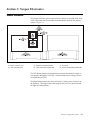
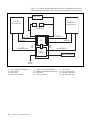
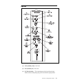
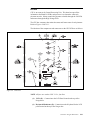
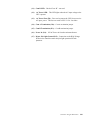
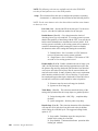
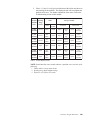
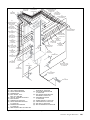
Contents
Section 3: Nexgen Electronics ............................................................ 3-3
General Information ........................................................................ 3-3
Nexgen Controller Box ................................................................... 3-5
Left Side .................................................................................... 3-5
Right Side .................................................................................. 3-7
GS-Series Pinsetter Electrical Start-Up ........................................... 3-9
Bottom ..................................................................................... 3-10
Top ........................................................................................... 3-10
Internal ........................................................................................... 3-11
I/O PCBs .................................................................................. 3-12
CPU PCB................................................................................. 3-13
High Voltage PCB ............................................................. 3-16
Machine Setup ............................................................................... 3-18
LCD Display/User Interface .................................................... 3-18
Diagnostic Modes .......................................................................... 3-22
Trouble Diagnostics................................................................. 3-22
Contact Closure Diagnostics (Switch Diagnostics)................. 3-22
Machine Cycle Diagnostics ..................................................... 3-23
Using the Diagnostics .................................................................... 3-23
Contact Closure Diagnostics (Switch Diagnostics)................. 3-23
Machine Cycle Diagnostics ..................................................... 3-24
Related Electronics ........................................................................ 3-27
Ball Detect - Photocell Triggering ........................................... 3-27
Foul Detect .............................................................................. 3-28
Reset Button ............................................................................ 3-28
Section 3: Nexgen Electronics
3-1
Intentionally Blank Page
3-2
Section 3: Nexgen Electronics
Section 3: Nexgen Electronics
General Information
The Nexgen electronic system consists of one control box mounted on the front
of the left pinsetter and several other items that monitor and help the pinsetter
operate. Figure 3-1.
Figure 3-1. Nexgen Controller Box Layout.
(1) INPUT / OUTPUT PCB
(4) HIGH VOLTAGE PCB
(2) NEXGEN CONTROLLER BOX
(5) LEFT LANE (ODD) PINSETTER
(3)
(6)
CPU PCB
RIGHT LANE (EVEN) PINSETTER
The CPU Board gathers switch information and sends out solenoid voltage to
each pinsetter through the I/O PCBs. Communication to the scoring system is
also handled by the CPU.
The High Voltage board is the entry point for the 3-phase power needed to run
the pinsetters. The High Voltage board supplies the power for the motors and
pin lights for both pinsetters.
Section 3: Nexgen Electronics
3-3
Figure 3-2 is a block diagram which shows the flow of information and power
paths between the pinsetters, several external devices and the electronic boxes.
(3)
TEL-E-FOUL
(1)
LEFT-HAND
GS-X PINSETTER
(2)
RIGHT-HAND
GS-X PINSETTER
(4)
BALL DETECT
(7)
SOLENOIDS
(7)
SOLENOIDS
(8)
SWITCHES
(8)
SWITCHES
(5)
CPU
(9)
MOTORS/PINLIGHT
(12)
I/O
PCB
(12)
I/O
PCB
(6)
HIGH
VOLTAGE
(9)
MOTORS/PINLIGHT
(10)
BALL ACCELERATOR
(11)
3 PHASE
POWER
Figure 3-2. Pinsetter Block Diagram
(1)
(4)
(7)
(10)
3-4
LEFT -HAND GS-X PINSETTER
BALL DETECT
SOLENOIDS
BALL ACCELERATOR
Section 3: Nexgen Electronics
(2)
(5)
(8)
(11)
RIGHT -HAND GS-X PINSETTER
CENTRAL PROCESSING UNIT PCB
SWITCHES
3 PHASE POWER
(3)
(6)
(9)
(12)
TEL-E-FOUL
HIGH VOLTAGE PCB
MOTORS / PINLIGHT
INPUT/OUTPUT PCB
Nexgen Controller Box
The Nexgen Controller box receives incoming 3-phase power and makes it
available to all motors, the pin lights and the transformer used to power the CPU
PCB. It also receives incoming switch information and controls the solenoids for
both machines. The following is a description of the boxes’ components and
connections. Refer to Figures 3-3, 3-4, and 3-5.
Left Side
Figure 3-3. Nexgen Controller - Left Side View
(1)
P1 (Right Side Function Switches, Trouble Light and Ball Door) This connection is the input for the switches located on the right side of
the odd lane (left) pinsetter. These switches include the “A,” “B,” “C,”
“D,” “SM,” “TS2” and “OOR.” The connection also provides the
output signals for the trouble light and the ball door solenoid for the left
pinsetter.
Section 3: Nexgen Electronics
3-5
3-6
Section 3: Nexgen Electronics
(2)
P2 (Masking Unit Control) - This connection provides the second ball
light signal to the masking unit for the odd numbered (left) lane.
(3)
P3 (Rear Box Control) - This connection provides input from the set,
reset, and stop/run switches mounted on the elevator of the odd lane
(left) pinsetter.
(4)
P4 (Ball Detect & Foul) - This connection provides input from the ball
detector, foul unit, and ball rack reset button for the odd (left) lane
(5)
P5 (Left Side Function Switches and Solenoids) - This connection
provides the input for the “TS1,” “G,” “EC” and pin count switches. It
provides output signals to the sweep release, spotting tong, stroke
limiter, and shark solenoids of the odd lane (left) pinsetter.
(6)
P6 (Pin Solenoids) - The pin holder (gripper) solenoids for the left
pinsetter are energized and de-energize via the voltages sent from this
connector
(7)
P7 (Pin Switches) - This connection provides input from the pin
holder switches and spotting tong (ST) switch for the left pinsetter.
(8)
P8 (FX Comline In) - This connection is used to connect to Brunswick
Scoring Systems. It provides two-way communication between the
Pinsetter CPU and the I/O PCB in Vector primary consoles or LGPs. If
software version 4.08.03 or higher is installed on the CPU, this connection is also used to connect the pinsetter to AS-90 scorers (see “Right
Side” connection - page 16)
(9)
P9 (FX Comline Out) - This connection is used for the Vector Scoring
Systems. It routes communication signals through the Pinsetter CPU to
the Vector lane devices such as TV Only monitors or Bowler Track.
(10)
P10 (Distributor Motor Power) - Provides 3-phase power to the odd
lane (left) pinsetter's distributor motor.
(11)
P11 (Sweep Motor Power) - Provides 3-phase power to the odd lane
(left) pinsetter's sweep motor.
(12)
P12 (Table Motor Power) - Provides 3-phase power to the odd lane
(left) pinsetter's table motor.
(13)
P13 (Pin Light Power) - Provides 208 or 230 VAC single phase to the
odd lane (left) pinsetter's pin light.
(14)
P14 (AC Power-In Cable) - Input power connection for the 3-phase
power. This voltage can be 208, 230 or 380 - 415 VAC.
(15)
SW2 (Main Power Switch) - Controls the 3-phase power entering the
box. In the off position, this switch will disable both pinsetters and the
ball accelerator.
Right Side
Figure 3-4 Nexgen Controller - Right Side View
(1)
P15 (Auxiliary Out) - Not Used
(2)
P16 (Auxillary In) - Not Used
(3)
P17 (Pin Switches) - This connection provides input from the pin
holder switches and spotting tong (ST) switch for the right pinsetter.
Section 3: Nexgen Electronics
3-7
3-8
Section 3: Nexgen Electronics
(4)
P18 (Pin Solenoids) - The pin holder (gripper) solenoids for the right
pinsetter are energized and de-energized via the voltage sent from this
connector.
(5)
P19 (Left Side Function Solenoids and Switches) - This connection
provides the input for the “TS1,” “G,” “EC” and pin count switches. It
provides output signals to the sweep release, spotting tong, stroke
limiter and shark for the even lane pinsetter.
(6)
P20 (Ball Detect & Foul) - This connection provides input from the
ball detector, foul unit, and ball rack reset button for the even lane
(7)
P21 (Rear Box Control) - This connection provides input from the set,
reset, and on/off switches mounted on the elevator of the even lane
pinsetter.
(8)
P22 (Masking Unit) - This connection provides the second ball signal
to the masking unit for the even lane.
(9)
P23 (Right Side Function Solenoids and Switches,) - This connection
is the input for all the switches on the right hand side of the even lane
pinsetter. These switches are “A,” “B,” “C,” “D,” “SM,” “TS2” and
“OOR.” The connection also provides the output signals for the trouble
light and the ball door solenoid for the even lane pinsetter.
(10)
P24 (Sweep Motor Power) - Provides full 3-phase power to the even
lane pinsetter's sweep motor.
(11)
P25 (Distributor Motor Power) - Provides 3-phase power to the even
lane pinsetter's distributor motor.
(12)
P26 (Ball Accelerator Motor Power) - Provides 3-phase power to the
ball accelerator motor.
(13)
P27 (Table Motor Power) - Provides 3-phase power to the even lane
pinsetter's table motor.
(14)
P28 (Pin Light) - Provides 208 or 230 VAC single phase to the even
lane pinsetter's pin light.
GS-Series Pinsetter Electrical Start-Up
1.
The transformers connections to the High Voltage PCB depends on the
operating voltage of the pinsetter. Reference Figure 3-5 & Table 1.
(1) TRANSFORMER PRIMARY TAP 1
(2) TRANSFORMER PRIMARY TAP 2
(3) UNUSED TRANSFORMER TAPS
J23
J22
J29
(2)
TRANSFORMER
PRIMARY TAP 2
J26
LS6
J28
(3)
UNUSED
TRANSFORMER
TAPS
L5
J30
J31
J36
J38
J24
J25
LS5
J27
J20
(1)
TRANSFORMER
PRIMARY TAP 1
J21
J37
J39 J40
F5
J42
J34
J43
F6
J41
Figure 3-5. Nexgen Voltage Settings
Input
Voltage
220V
380V
415V
208V
200V
TRANSFORMER 1
Wire
Transformer
Tap
BLK
BLK/RED
BLK/WHT
BLK/YEL
BLK
BLK/YEL
BLK/RED
BLK/WHT
BLK
BLK/WHT
BLK/YEL
BLK/RED
Common
230V
Not Used
Not Used
Common
208V
Not Used
Not Used
Common
200V
Not Used
Not Used
High Voltage
PCB Terminal
J37
J25
Not Used
J42
J37
J25
J42
Not Used
J37
J25
J42
Not Used
Input
Voltage
220V
380V
415V
208V
200V
TRANSFORMER 2
Wire
Transformer
Tap
BLK
BLK/RED
BLK/WHT
BLK/YEL
BLK
BLK/YEL
BLK/RED
BLK/WHT
BLK
BLK/WHT
BLK/YEL
BLK/RED
Common
230V
Not Used
Not Used
Common
208V
Not Used
Not Used
Common
200V
Not Used
Not Used
High Voltage
PCB Terminal
J37
J25
Not Used
J43
J37
J25
J43
Not Used
J37
J25
J43
Not Used
Table 1. Transformer Taps
Section 3: Nexgen Electronics
3-9
Bottom
Mounted on the bottom of the Nexgen box are two transformers. The transformers use an incoming 230 Volt or 208 Voltage from the High Voltage PCB
and reduces it to 26VAC. This voltage is then sent to the CPU PCB (J11) where
it is used to create the DC voltages for pinsetter operation.
Top
Figure 3-6. Nexgen Controller - Top View
3-10
Section 3: Nexgen Electronics
(1)
Enter Key - This push button key has two functions. During pinsetter
setup it is used to select the left or right lane. Once a configuration
mode has been selected using the Mode key, it is used to display the
different options available for the mode.
(2)
Mode Key - This push button key allows the mechanic to select the
different pinsetter setup modes used to configure how the machine
should operate.
(3)
Reset Keys - These push button keys cause the pinsetter to cycle to the
next ball. Push button switches with the same function are mounted on
the ball rack for the bowler's use and on the rear control box located on
the elevator for the mechanics' use .
(4)
Set Keys - These push button keys causes the last combination of pins
to be set. Push button switches with the same function are located on
the rear control box mounted on the elevator.
(5)
Stop/Run Switches - This toggle switch is used to manually stop or
start the pinsetter. Turning this switch to the Stop position will deenergize the lane power relays on the High Voltage PCB for the pinsetter.
(6)
Up/Down Arrow Keys - These push button keys allow the mechanic to
setup the option being displayed.
(7)
LCD Display - This display shows the frame count, error codes and
setup information for both pinsetters.
Internal
Internally, the Nexgen Controller box contains four circuit boards; a CPU PCB,
a High Voltage PCB and two I/O PCBs. Refer to Figure 3-7
(1)
(2)
(3)
(4)
INPUT / OUTPUT PCB
NEXGEN CONTROLLER BOX
CPU PCB
HIGH VOLTAGE PCB
Figure 3-7. Nexgen Controller - Internal View
Section 3: Nexgen Electronics
3-11
I/O PCBs
I/O is an acronym for input and output. These printed circuit boards receive the
incoming information from the pinsetter and pass it on to the CPU. The CPU
then makes an appropriate decision and sends its commands back to the pinsetter through the I/O printed circuit board. Refer to Figure 3-8.
Figure 3-8. I\O PCB
(1) A,B,C,D, TS2, SM, OOR SWITCHES,
LEFT BALL DOOR SOLENOID,
TROUBLE LIGHT
(4) SHARK SWITCH, SWEEP, STROKE
SOLENOID, AND TS1, 6, SS, EC
SWITCHES
(7) COM A
(10) CPU CONNECTION
3-12
Section 3: Nexgen Electronics
(2) BALL LIGHT
(3)
BALL DETECT, FOUL,
BALL RACK RESET
(5) PW 1-10 ST SWITCHES
(6)
COM B
(8) SET RESET, STOP/RUN
(9)
PW 1-10 SOLENOID
CPU PCB
CPU is an acronym for Central Processing Unit. This board accepts all the
information from both I/O PCBs, and processes it to determine what each
pinsetter must do. It then controls the pinsetter solenoids through the I/O PCBs
and motors through the High Voltage PCB.
The CPU has a memory that retains the status and frame count of each pinsetter.
Refer to Figures 3-9 & 3-11.
The function of the components and connectors on the CPU PCB are as follows:
Figure 3-9. CPU PCB.
NOTE: All fuses are rated at 250V 3.15A - fast blow.
(1)
LCD (J1) - Connection to the LCD Panel located at the top of the
Nexgen box.
(2)
Keyboard Membrane (J2) - Connection to the Keyboard for the LCD
panel located at the top of the Nexgen box.
Section 3: Nexgen Electronics
3-13
(3)
Stop/Run Switches (J3) - Connection to the stop/run switches at the
top of the Nexgen box.
(4)
Machine Switches (J4, J14) - Input connection for the following
machine signals: TS1 ,G, pin count, EC, A, B, C, D, TS2, SM, ST and
OOR switches, all 10 pin holders switches, rear control box set and reset
switches, ball rack reset switch, foul unit, and ball detector. J4 connects
to the left pinsetter while J14 is for the right pinsetter.
(5)
Pin Solenoid,Comline,Stop/Run (J5, J13) - This connection supplies
voltage to the pinholder solenoids and ball lift and is the connection for
the Stop/Run Switch located on the elevator. The communication to the
Vector scorer system is also handled by this connection. J5 connects to
the right pinsetter and J13 connects to the left pinsetter.
(6)
Machine Solenoids,Trouble Light,Ball Detect (J8 ,J9) - Connection
that supplies voltage to the spotting tong, sweep release, shark, and ball
door solenoids and the trouble lights. This connection is also provides
input for the ball detectors. J8 is for the left pinsetter and J9 is for the
right pinsetter.
(7)
DC Power LEDs - These LEDs light when the DC voltage for the 26
Volt circuitry is operating.
(8)
DC Power Fuses (F1-F7, F9, F10) - Fuses used to protect the 26VDC
circuitry. These fuses are rated at 250V 3.15A - fast blow.
F1 (RH Pinsetter) F10 (LH Pinsetter) - 1,2,3 Pin Gripper Solenoids,
Spotting Tong Solenoid
F2 (RH Pinsetter) F9 (LH Pinsetter) - 4,5,6 Pin Gripper Solenoids,
Sweep Release Solenoid
F3 (RH Pinsetter) F7 (LH Pinsetter) - 7,8,9 Pin Gripper Solenoids,
Stroke Limiter Solenoid
F4 - left Ball Detect, right Ball Detect, left Trouble Light, and right
Trouble Light
F5 (RH Pinsetter) F6 (LH Pinsetter) - 10 Pin Gripper Solenoids Shark
Solenoid, and Ball Door Solenoid
3-14
Section 3: Nexgen Electronics
(9)
CPU LED - Labeled “CPU” this LED lights when the microprocessor
is operating properly.
(10)
Com A LED - Labeled “Com A” this LED lights when communication
to the Frameworx scorers is functioning properly.
(11)
Com B LED - Labeled Com “B” - not used.
(12)
AC Power LED - This LED lights when the AC input voltage to the
CPU is present.
(13)
AC Power Fuse (F8) - Fuse used to protect the CPU from excessive
AC input power. This fuse are rated at 250V 3.15A - fast blow.
(14)
Com A Termination (J10) - Com A termination jumper.
(15)
Com B Termination (J12) - Com B termination jumper.
(16)
Power In (J11) - 26VAC Power in from the main transformer.
(17)
Motor, Pin Light Control (J15) - Connection to the High Voltage
PCB used to control the motor and pin light operation for both
pinsetters .
Section 3: Nexgen Electronics
3-15
High Voltage PCB
The High Voltage board is the entry point for the 3-phase power needed to run
the pinsetters. The High Voltage board uses this power to control the motors
and pin lights for both pinsetters. Fuses on the PCB are used to protect the
motors and pin lights. Refer to Figure 3-10.
Figure 3-10. Nexgen Controller - High Voltage PCB
The function of the component on the High Voltage PCB are:
(1)
3-16
Section 3: Nexgen Electronics
Motor/Pinlight Control (J3) - Connection for the cable originating at
the CPU PCB. The High Voltage is “told” when to turn the motors and
pinlights ON/Off through this connection.
(2) Left Hand Power Relays - Main power relays for each phase of power
entering the Nexgen box. When energized power is made available to the
left pinsetter’s motor and pin light circuitry.
(3) Right Hand Power Relays - Main power relays for each phase of
power entering the Nexgen box. When energized power is made available to the right pinsetter’s motor and pin light circuitry.
(4) Table Motor CW Fuse(F1,F4) - Fuses used to protect the table motor
circuitry from excessive current when turning the table motor on in a
clockwise rotation. F1 is for the left pinsetter, F4 is for the right pinsetter. The fuses are rated at 250V 8.0A - fast blow.
(5) Table Motor CCW Fuse(F2,F3) - Fuse used to protect the table motor
circuitry from excessive current when turning the table motor on in a
counterclockwise rotation. F3 is for the left pinsetter, F2 is for the right
pinsetter. The fuses are rated at 250V 8.0A - fast blow.
(6) Pin Light Fuses (F5,F6) - Fuses used to protect the pin lights from
excessive current. F5 is for the left pinsetter, F6 is for the right pinsetter.
The fuses are rated at 250V 5A - slow blow.
(7) Power Connectors - Connections to pinsetter motors and pinlight.
Section 3: Nexgen Electronics
3-17
Machine Setup
LCD Display/User Interface
Setup and diagnostics for the both pinsetters is performed using the Nexgen
LCD Panel. Refer to Figure 3-12.
Figure 3-11. Nexgen Controller - LCD Panel
Four keys on the control panel are used to navigate the user menu.
3-18
Section 3: Nexgen Electronics
(1)
Mode Key - Use this button to step through the pinsetter modes when
the mode selection menu is being displayed or to return to the mode
selection menu.
(2)
Enter Key - The function of this key is dependent on what is being
displayed on the LCD. If the mode displayed on the LCD does not have
a submenu, this key allow the user to select the left or right lane.
When the mode displayed on the LCD has a submenu, the Enter key
steps through the submenu selections.
(3)
Up/Down Arrows - The function of this key is dependent on what is
displayed on the LCD. When the mode selection menu is displayed,
this key allows the user to step through the pinsetters modes. When in a
submenu, the arrow keys allow the user to toggle the choices of the
feature selected in the submenu.
During power up of the Nexgen Controller, the unit it goes through a boot up
sequence. The Controller’s LCD display will first display “Brunswick GS-X”
and then display “Software V 4.08 / EPROM OK”. Once the controller successfully boots up, the mode selection menu is displayed.
The Mode selection menu has the following choices:
Frmwrx -
Use this setting when the GS Certified Pre-owned pinsetter is
connected to Frameworx and/or Vector scoring systems. This
selection does not have a submenu.
Tenpin -
Use this setting when the GS Certified Pre-owned pinsetter is
NOT connected to a scoring system or is operating in a standalone mode. This selection does not have a submenu.
AS-90 -
This setting appears only if software version 4.08.03 or higher
is installed in the Nexgen box. Use this setting when a GS
Certified Pre-owned is connected to an AS-80, or AS-90
scorer. This selection does not have a submenu
Diag -
This selection allows the mechanic to put the selected pinsetter into cycle diagnostics mode. This selection does not have a
submenu.
Motor -
This selection allows the mechanic to manually run the
pinsetter motors on the selected machine. A submenu that
appears when the stop/run switch is set to the run position has
the following choices:
Table CW -
This selection turns the table motor of the selected
lane in a clockwise rotation.
Table CCW -
This selection turns the table motor of the selected
lane in a counterclockwise rotation.
Distrib -
This selection turns the distributor motor of the
selected lane on.
Sweep -
This selection turns the sweep motor of the selected
lane on.
Pinlight -
This selection caused the pinlight of the selected pinsetter to
turn on.
Section 3: Nexgen Electronics
3-19
NOTE: The following selections are available only when the STOP/RUN
switches for both pinsetters are in the STOP position.
Setup - This selection allows the user to configure the pinsetter’s operating
characteristic. A submenu for this selection has the following choices:
NOTE: Use the enter button to select the desired choice and the arrow buttons
to choose yes or no.
Left Lane # ## - Sets the lane ID for the lane pair. Use the arrow
keys to select the left (odd) lane number for the lane pair.
Double Detect: (Y or N) - Gives the pinsetter the choice of
detecting pin activity on second ball. If a scoring system is present
that has the capability of interfacing with the CPU, it can use the pin
holder switch information to determine the bowler's pinfall. If no
scoring system is available, or the scoring system uses a scanner or
camera for determining pinfall, turning this switch on disables
the detection stroke of the setting table during the second ball.
Y - Double Detect - Set if a scanner or CCD Camera are
not used. (Frameworx scoring system) (default)
N - Single Detect - Set if a scanner, CCD Camera or VPS
are used or if no scoring system is used.
Enable OOR: (Y or N) - Enable or disables the out-of-range cycle.
ABC, the FIQ and many other bowling organizations require that
the pinsetter stop and any deadwood (pins that have been knocked
over but are still in the field of play) must be removed before the
next ball can be rolled. In many countries, this is not a requirement
and it interferes with the bowler’s flow of bowling. If your center
has sanctioned leagues that require deadwood be removed before a
second ball is rolled, this switch should be in the left position.
Y - Pinsetter stops for an out-of-range pin. (default)
N - Ignores an out-of-range pin.
Table Delay: (Y or N) - This selection controls the delay of the
setting table operation after the sweep drops to a guarded position.
Y - Delayed setting table - ABC, FIQ..., compliant delay.
(default)
N - Quick setting table - No delay after sweep drop.
Distrib Stop: (Y or N) - This selection determines if the distributor
will stop after all 10 pins have been delivered to the pin holders
while waiting for a 2nd ball cycle. The suggested setting for this
option is “N”.
Y - Stop enable - Distributor stops after ten pins have
loaded while waiting for a 2nd ball.
N - Stop disabled - Continuous distributor operation while
loading pin. (default)
3-20
Section 3: Nexgen Electronics
Enable 50 ERR (Y or N) - This selection allows pinfall detection
to be monitored or ignored during machine cycle diagnostics.
Y - Enable Codes (default)
N - Disable Codes
Enable Foul: (Y or N) - This selection allows you to accept or
ignore the foul signal coming from the foul unit.
Y - The pinsetter will accept the foul signal (default)
N - Foul Signals are ignored.
Dist Slow Start: (Y or N) - This selection is available on machines
with software version 4.08.02 and higher. The selection determines
whether the distributor will start slowly and gradually increase
speed or start at full speed. The suggested setting for this option
is”N”.
Y - Slow start enabled
N - Slow start is disabled
Long Err Codes: (Y or N) - This selection is available on
machines with software version 4.08.02 and higher. The selection
determines whether the display will show error code using the
standard 2 digit code or extended code.
Y - Display error codes using extended format
N - Display error codes using 2 digit format
Pinlight: (Y or N) - This selection is available on machines with
version 4.08.02 and higher. This selection turns on the pinlight so
that the pins are illuminated even when the machine is unassigned.
Y - Pinlight on
N - Pinlight off
SW Diag - This selection allows the user to check the switches on the pinsetters. The display will list the switches that are actuated (closed) are used during
the time the check is being made. This mode can be used to verify that switches
are working properly and the wiring A submenu for this selection has the
following choices:
Pin SW (Left) - This selection checks the pinholder switches and
displays the ones that are actuated on the left pinsetter.
Table SW (Left) - This selection checks the Table switches A, B,
C , D, TS1, and TS2 and displays the ones that are actuated on the
left pinsetter.
Section 3: Nexgen Electronics
3-21
Mach SW (Left) - This selection checks the machine switches EC,
G, SM, OOR, ST, Pincount Switch, and displays the ones
that are actuated on the left pinsetter.
EXT SW (Left) -This selection checks the external switches Ball
Detect, Foul, Set And Reset and displays the ones that are actuated
on the left pinsetter.
Pin SW (Right) - This selection checks the pinholder switches and
displays the ones that are actuated on the left pinsetter.
Table SW (Right) - This selection checks the Table switches A, B,
C , D, TS1, and TS2 and displays the ones that are actuated on the
right pinsetter.
Mach SW (Right) - This selection checks the machine switches
EC, G, SM, OOR, ST, Pincount Switch, and displays the
ones that are actuated on the right pinsetter.
EXT SW (Right) - This selection checks the external switches Ball
Detect, Foul, Set And Reset and displays the ones that are actuated
on the right pinsetter.
Diagnostic Modes
Trouble Diagnostics
The GS Certified Pre-owned pinsetter contains a means of diagnosing pinsetter
problems and will shut down a pinsetter if a fault is detected. When a problem
occurs, the pinsetter will shut down and the trouble light on the top of the
elevator will start to flash. The error code displayed on the LCD Display at the
top of the Nexgen Controller can be used to diagnose the problem.
Contact Closure Diagnostics (Switch Diagnostics)
In addition to trouble diagnostics, the GS Certified Pre-owned pinsetter is
capable of performing two diagnostic modes for testing pinsetter operations;
one mode, contact closure diagnostics, checks the switches on the pinsetter and
displays which switches are used during the time the check is being made. This
mode can be used to verify that switches are working properly and the wiring
between the Nexgen Controller box and the individual switches is correct.
3-22
Section 3: Nexgen Electronics
Machine Cycle Diagnostics
The other mode, machine cycle diagnostics, puts the pinsetter into a continuous
operating cycle in which the pinsetter operates as if it was in a ten pin bowling
mode, with the following exceptions. Instead of waiting for a ball detect, a five
second time signal from the CPU starts the pinsetter cycle. The pinsetter will
continue to set, reset, sweep and reload pins as long as it is switched into the
diagnostic mode. Fouls will be ignored during the diagnostics, and in
Frameworx scoring systems, pinsetter cycles will not be counted at the
Manager's Control location. Diagnostic faults (failures) are active during
diagnostics and can stop the pinsetter if a jam or some form of failure is detected.
Using the Diagnostics
Contact Closure Diagnostics (Switch Diagnostics)
1.
The contact closure diagnostics can only be performed when both
pinsetters are off (stop/run switches in the stop positions) The pinsetter
is selected by having the following conditions available.
a.
The trouble light cannot be lit.
b.
The rear mechanic switch on.
c.
Both the left and the right stop/run switches on the Nexgen
Controller box must be switched to the “stop” position. Refer to
Figure 3-5
d.
To activate Contact Closure diagnostics, press the [Mode] key on
the control panel until the mode “SW Diag” appears on the
display.
e.
Press the [Enter] key to step through the display options.
Pin SW (Left) - Displays the pinholder switches that are
actuated on the left pinsetter. A “-” indicates the switch is
open.
Table SW (Left) - Display switches A, B, C, D, TS1, and
TS2 of the left pinsetter if actuated. A “-” indicates the
switch is open.
Mach SW (Left) - Displays switches EC, G, SM, OOR, ST,
and SS (Pincount Switch) of the left pinsetter if actuated. A
“-” indicates the switch is open.
EXT SW (Left) - Displays the Ball Detect, Foul, Set And
Section 3: Nexgen Electronics
3-23
Reset Switches if actuated for the left pinsetter. A “-”
indicates the switch is open.
Pin SW (Right) - Displays the pinholder switches that are
actuated on the right pinsetter. A “-” indicates the switch is
open.
Table SW (Right) - Display switches A, B, C, D, TS1, and
TS2 of the right pinsetter if actuated. A “-” indicates the
switch is open.
Mach SW (Right) - Displays switches EC, G, SM, OOR,
ST, and SS (Pincount Switch) of the right pinsetter if
actuated. A “-” indicates the switch is open.
EXT SW (Right) - Displays the Ball Detect, Foul, Set And
Reset Switches if actuated for the right pinsetter. A “-”
indicates the switch is open.
Machine Cycle Diagnostics
1.
To enter into this mode, the following conditions are necessary.
a.
The trouble light cannot be lit.
b.
The rear mechanic switch must be on.
c.
Either the left or right stop/run switch on the Nexgen Controller
box must be switched to the “stop” position. This will be dependent on which pinsetter is being tested. Refer to Figure 3-5
2.
To activate cycle diagnostics, press the [Mode] key on the control panel
until the mode “Diag” appears on the display.
3.
Turn either the left or right stop/run switch on the Nexgen Controller to
the “run” position. This will be dependent on which pinsetter is being
tested.
4.
If a pinsetter stops during diagnostics and the trouble light is lit, check
the error code displayed on top of the Nexgen Controller box. Refer to
Figure 3-5
NOTE: In order to see error codes 50-59 (Detect 1 - Detect 9, Detect 10)
in Machine Diagnostics, the Enable 50 ERR must be set to Y. See Pages 3-19 &
3-22 for an explanation of the pinsetter setup.
3-24
Section 3: Nexgen Electronics
5.
Tables 3-13 and 3-14 will give an indication of the failure and where to
start looking for the problem. The displayed code will not pinpoint the
problem in all cases. For further explanation of the codes, refer to the
Troubleshooting section of this manual.
Invalid Spotting
M achine Tongs
State
Switch
Table
Swe e p As s e mbly
Position
"A"
Switch
"G" Switch
"SM" Switch
0 (90)
(Invld 0)
Closed
Home
Closed
Open
Sweep
Up
Open
N ot
Forward
1 (91)
(Invld 1)
Closed
N ot
Home
Open
Open
Sweep
Up
Open
N ot
Forward
2 (92)
(Invld 2)
Closed
N ot
Home
Open
Closed
Sweep
Down
Open
N ot
Forward
3 (93)
(Invld 3)
Open
Home
Closed
Open
Sweep
Up
Open
N ot
Forward
4 (94)
(Invld 4)
Open
N ot
Home
Open
Open
Sweep
Up
Open
N ot
Forward
5 (95)
(Invld 5)
Open
N ot
Home
Open
Closed
Sweep
Down
Open
N ot
Forward
Table 2. Invalid Machine States.
NOTE: Invalid machine states usually indicate a problem exists with one of the
following:
1. Faulty table or sweep motor break.
2. Spotting tong clutch malfunctioning.
3. Defective A, G, SM, or ST switch.
Section 3: Nexgen Electronics
3-25
Std. Extended
Code Code
Std. Extended
Code Code
P0 Pin OOR Out-of-Range
62 C Found
Switch C is Not Expected But Found
01 Pin1 Ld
Pin Loading Time Out Pin 1
63 D Found
Switch D is Not Expected But Found
02 Pin2 Ld
Pin Loading Time Out Pin 2
64 SMFound
Switch SM is Not Expected But Found
03 Pin3 Ld
Pin Loading Time Out Pin 3
65 G Found
Switch G is Not Expected But Found
04 Pin4 Ld
Pin Loading Time Out Pin 4
66 STFound
Switch ST Is Not Expected But Found
05 Pin5 Ld
Pin Loading Time Out Pin 5
67 OORFound SW. OOR is Not Expected But Found
06 Pin6 Ld
Pin Loading Time Out Pin 6
70
A Ntfnd
Switch A Expected But Not Found
07 Pin7 Ld
Pin Loading Time Out Pin 7
71 B Ntfnd
Switch B Expected But Not Found
08 Pin8 Ld
Pin Loading Time Out Pin 8
72 C Ntfnd
Switch C Expected But Not Found
09 Pin9 Ld
Pin Loading Time Out Pin 9
73 D Ntfnd
Switch D Expected But Not Found
10 Pin10 Ld Pin Loading Time Out Pin 10
74 SM Ntfnd
Switch SM Expected But Not Found
50 Detect10 #10 Pin Not Detected in Diagnostics
75 G Ntfnd
Switch G Expected But Not Found
Detect1
#1 Pin Not Detected in Diagnostics
76 STNtfnd
Switch ST Expected But Not Found
52 Detect2
#2 Pin Not Detected in Diagnostics
90
Invld 0
Invalid Machine State 0
53
Detect3
#3 Pin Not Detected in Diagnostics
91
Invld 1
Invalid Machine State 1
54 Detect4
#4 Pin Not Detected in Diagnostics
92
Invld 2
Invalid Machine State 2
55 Detect5
#5 Pin Not Detected in Diagnostics
93
Invld 3
Invalid Machine State 3
56 Detect6
#6 Pin Not Detected In Diagnostics
94
Invld 4
Invalid Machine State 4
Invld 5
Invalid Machine State 5
51
57
Detect7
#7 Pin Not Detected in Diagnostics
95
58
Detect8
#8 Pin Not Detected in Diagnostics
EJ ElevJam
Elevator Jam
59
Detect9
#9 Pin Not Detected in Diagnostics
EL Pin Cnt
Pin Count Switch Shorted for 5 Seconds
60 A Found
Switch A is Not Expected But Found
J1 TS1 Jam
Jam Switch TS1
61 B Found
Switch B is Not Expected But Found
J2 TS2 Jam
Jam Switch TS2 (Tower)
BA
Accelerator Motor (overload)
Table 3-12. Error Codes.
NOTE: Nexgen Electronics displays either Standard Code or Extended Code.
3-26
Section 3: Nexgen Electronics
Related Electronics
Ball Detect - Photocell Triggering
The photocell is an optical device used to detect a ball rolling down the lane. It
consists of a transmitter/receiver device and a retroreflector. The transmitter/
receiver device is mounted on the ball return kickback and the retroreflector is
mounted on the division kickback. They are positioned directly across from
each other at 25 mm (1") above the capping. Refer to Figures 3-13 and 3-14.
The transmitter sends an infrared beam across the lane to the retroreflector
which reflects the beam back to the receiver. When any object cuts this beam,
the receiver sends a pulse to the Pinsetter CPU. The Pinsetter CPU then cycles
the corresponding pinsetter.
WARNING: A strong light source such as a camera's electronic flash may
cause the pinsetter to trigger.
(1) KICKBACK
(2) PHOTOCELL ASSEMBLY
(3) CAPPING
Figure 3-13. Ball Detect.
(1)
DIVISION
KICKBACK
(2)
RETROREFLECTOR
1"
(25 mm)
(1) DIVISION KICKBACK
(2) RETROREFLECTOR
(3) CAPPING
(3)
CAPPING
Figure 3-14. Retroreflector.
Section 3: Nexgen Electronics
3-27
Foul Detect
The foul detect is located at the foul line and is mounted between the pair of
lanes on the ball return capping. Retroreflectors, mounted on divisions, return
the beam to the foul detect. A foot or some other object will interrupt this beam
and a signal is sent to the Pinsetter CPU to make the pinsetter set ten new pins if
the machine is in a first ball foul situation while bowling a ten pin game format.
The foul detect will not register a foul when the beam is broken by a bowling
ball.
Reset Button
A bowler’s reset button is located on the side of the ball rack. This switch
parallels the reset switch on the Nexgen Controller box and rear Control Box on
the elevator. Its purpose is to cycle the pinsetter to the next ball.
Cables and Wiring
Cable Connections
The Nexgen box interconnects with several external devices that assist in the
operation of the pinsetters.
The cables are labeled for easy identification in the event the Nexgen box needs
to be replaced. However, care must be exercised when making these changes as
problems can occur if cables are swapped between the left and right connections. Refer to Figure 3-15.
3-28
Section 3: Nexgen Electronics
(5)
BALL
ACCELERATOR
47-245423-004
(3)
RIGHT-HAND
PINSETTER
(2)
LEFT-HAND
PINSETTER
(14)
PIN HOLDER SWITCHES
AND SOLENOIDS
47-245421-004
(13)
LEFT-HAND
SIDE FUNCTION
47-142673-000
(11)
REAR CONTROL BOX
47-245422-003
RI
GH
T
(14)
PIN HOLDER SWITCHES
AND SOLENOIDS
47-245421-004
MA
CH
IN
E
P1
6
P1
5
P1
8
P1
(13)
LEFT-HAND
SIDE FUNCTION
47-142673-000
7
LE
FT
P1
9
MA
CH
IN
E
P1
(11)
REAR CONTROL BOX
47-245422-003
(19)
BALL ACCELERATOR
47-245423-004-000
P2
P2
1
P2
0
P3
P4
(9)
RIGHT-HAND
SIDE FUNCTION
47-142674-000
(15)
DISTRIBUTOR
MOTOR
47-142616-000
P2
3
P2
(9)
RIGHT-HAND
SIDE FUNCTION
47-142674-000
2
P5
P2
5
P6
P7
(10)
MASKING UNIT
ADAPTER
47-142690-000
P2
7
P8
6
(17)
TABLE MOTOR
47-142615-000
P1
0
P1
2
(15)
DISTRIBUTOR
MOTOR
47-142616-000
P1
1
4
P2
P9
(12)
BALL DETECT, FOUL,
BALL LIFT ADAPTER
47-142672-000
P2
)
(1 EN S
C
XGONI
E
N TR
X
C
E O
EL B
(16)
SWEEP MOTOR
47-142617-000
(18)
PIN LIGHT
47-225416-004
(4)
MASKING UNIT
(16)
SWEEP MOTOR
47-142617-000
(17)
TABLE MOTOR
47-142615-000
(10)
MASKING UNIT
ADAPTER
47-142690-000
(18)
PIN LIGHT
47-225416-004
(12)
BALL DETECT, FOUL,
BALL LIFT ADAPTER
47-142672-000
(4)
MASKING UNIT
(8)
POWER IN
68-100453-004
(6)
OPTICAL TRIGGER
PHOTOCELL
(7)
BALL RETURN
(1)
(2)
(3)
(4)
(5)
(6)
(7)
(8)
(9)
(10)
(11)
NEXGEN ELECTRONIC BOX
LEFT-HAND PINSETTER
RIGHT-HAND PINSETTER
MASKING UNIT
BALL DETECT, FOUL,
BALL LIFT ADAPTER
OPTICAL TRIGGER PHOTOCELL
BALL RETURN
POWER IN 68-100453-004
RIGHT-HAND SIDE FUNCTION
47-142674-000
MASKING UNIT ADAPTER
47-142690-000
REAR CONTROL BOX 47-245422-003
(12) BALL DETECT, FOUL, BALL LIFT
ADAPTER 47-142672-000
(13) LEFT-HAND SIDE FUNCTION
47-142673-000
(14) PIN HOLDER SWITCHES AND
SOLENOID 47-245421-004
(15) DISTRIBUTOR MOTOR
47-142616-000
(16) SWEEP MOTOR 47-142617-000
(17) TABLE MOTOR 47-142615-000
(18) PIN LIGHT 47-225416-004
(19) BALL ACCELERATOR 47-245423-004
Figure 3-15. GS Certified Pre-owned Pinsetter with Nexgen Electronics.
Section 3: Nexgen Electronics
3-29
INTENTIONALLY BLANK PAGE
3-30
Section 3: Nexgen Electronics
11 X 17 HERE
Section 3: Nexgen Electronics
3-31
BACK OF 11 X 17 HERE
3-32
Section 3: Nexgen Electronics
(1)
TO BALL
ACCELERATOR
MOTOR
SW 2
SW 3
(2) GND
(2)
GND
BLK #1
4
RED #2
WHT #3
(3)
TO P26 ON
NEXGEN
BOX
1
SW 1
SW 2
SW 3
P26
SW 1
GRN
2
6
Figure 3-17. Ball Accelerator Motor Cable Assembly (Part No. 47-245423-004)
(1) TO BALL ACCELERATOR MOTOR
(1)
TO TABLE
MOTOR
U2/V1
W2/U1
(2) GND
BLK #1
BLK #2
BLK #3
GRN/YEL
BLK #3
BLK #1
BLK #2
GRN/YEL
1
2
3
4
P15/P18
V2/W1
(3) TO P26 ON NEXGEN BOX
(2) GROUND
(3)
TO P12/P27 ON
NEXGEN
BOX
Figure 3-18. External Table Motor Cable Assembly (Part No. 47-142615-000)
(1)
U2/V1
TO DISTRIBUTOR
W2/U1
(2) GND
BLK #1
BLK #2
P17/P20
V2/W1
(3) TO P15/P18 ON NEXGEN BOX
(2) GROUND
(1) TO TABLE MOTOR
BLK #3
GRN/YEL
1
2
3
4
5
6
BLK #3
BLK #1
BLK #2
GRN/YEL
(4) NC
(4) NC
(3)
TO P17/P20 ON
NEXGEN
BOX
Figure 3-19. External Distributor Motor Cable Assembly (Part No. 47-142616-000)
(1) TO DISTRIBUTOR
(2) GROUND
(3) TO P17/P20 ON NEXGEN BOX
(4) NO CONNECTION
Section 3: Nexgen Electronics
3-33
(1)
TO SWEEP
MOTOR
U2/V1
W2/U1
(2) GND
BLK #1
BLK #2
P16/P19
V2/W1
BLK #3
GRN/YEL
1
2
3
4
5
BLK #3
BLK #1
BLK #2
GRN/YEL
(4) NC
(3)
TO P11/P24 ON
NEXGEN
BOX
Figure 3-20. Sweep Motor Cable Assembly (Part No. 47-142617-000)
(1) TO SWEEP MOTOR
(2) GROUND
1
2
3
4
5
6
7
8
9
10
11
12
13
14
15
(1)
TO
SETTING
TABLE
16
17
18
19
20
21
22
23
24
25
26
27
28
29
30
31
32
33
34
35
36
37
(4) NO CONNECTION
(3) TO P11/P24 ON GS
NEXGEN BOX
(15) GRD
WHT
(2) NC
(2) NC
(2) NC
(5) PIN SW #1
(6) PIN SW #2
(7) PIN SW #3
(8) PIN SW #4
(9) PIN SW #5
(10) PIN SW #6
(11) PIN SW #7
(12) PIN SW #8
(13) PIN SW #9
(14) PIN SW #10
BRN
GRN
YEL
GRY
ROS
BLU
RED
BLK
VIO
GRN/ROS
1
2
3
4
(3)
5
6 TO PIN SWITCHES
P7-P17
7
8
9
10
11
12
(2) NC
RED/BLU
WHT/GRN
BRN/GRN
WHT/YEL
YEL/BRN
WHT/GRY
GRY/BRN
WHT/ROS
ROS/BRN
WHT/BLU
BRN/BLU
WHT/RED
BRN/RED
(16) PIN SOL #1
(17) PIN SOL #2
(18) PIN SOL #3
(19) PIN SOL #4
(20) PIN SOL #5
(21) PIN SOL #6
(22) PIN SOL #7
(23) PIN SOL #8
(24) PIN SOL #9
(25) PIN SOL #10
A+
B+
C+
BRN/BLK
GRY/GRN
OS SW (ST)
D+
1
2
3
4
5
6
7
8
9
10
11
12
13
14
(4)
TO PIN SOLENOIDS
P6-P18
(2) NC
(2) NC
(2) NC
(2) NC
(2) NC
(2) NC
Figure 3-21. External Setting Table Cable Assembly (Part No. 47-245421-004)
(1) TO SETTING TABLE
(2) NO CONNECTION
(3) TO PIN SWITCHES
P7-P17
(4) TO PIN SOLENOIDS
P6-P18
(5) PIN SWITCH #1
(6) PIN SWITCH #2
(7) PIN SWITCH #3
3-34
Section 3: Nexgen Electronics
(8)
(9)
(10)
(11)
(12)
(13)
(14)
(15)
(16)
PIN SWITCH
PIN SWITCH
PIN SWITCH
PIN SWITCH
PIN SWITCH
PIN SWITCH
PIN SWITCH
GROUND
PIN SOL #1
#4
#5
#6
#7
#8
#9
#10
(17)
(18)
(19)
(20)
(21)
(22)
(23)
(24)
(25)
PIN
PIN
PIN
PIN
PIN
PIN
PIN
PIN
PIN
SOL
SOL
SOL
SOL
SOL
SOL
SOL
SOL
SOL
#2
#3
#4
#5
#6
#7
#8
#9
#10
WHT
(2)
SET
TO
(1)
P3/P24
BRN
(3)
RESET
(4)
RUN
YEL
GRY
STOP
3
4
5
(1)
TO P3/P24
6
1
GRN
YEL
GRY
WHT
(4) RUN/STOP
SWITCH
(2) SET
BRN
GRN
(3) RESET
2
7
8
Figure 3-22. Rear Control Box Cable Assembly (Part No. 47-245422-003 or 47-240071-004)
(1) TO P3/P24
(2) SET
(3) RESET
(4) RUN/STOP SWITCH
Section 3: Nexgen Electronics
3-35
1
Section 3: Nexgen Electronics
26
2
3
4
5
6
2
3
4
5
6
YEL
31 25
13
24
(12)
4 WIRES BLUE
COMMON SOLENOID 7, 8, 9
(11)
4 WIRES BLUE
COMMON SOLENOID 4, 5, 6
(10)
4 WIRES BLUE
COMMON SOLENOID 1, 2, 3
(9)
11 WIRES RED
COMMON FOR ALL
10 PIN CUP SWITCHES
14
1 2 3 4
BLU
WHT
12
(4) BLOCK 5
(1) PIN HOLDERS 1-10
(2) COIL RESISTANCE ALMOST EQUAL (5) BLOCK 4
(6) BLOCK 3
TO 26 OHMS
(3) BLOCK 6
Figure 3-25. Setting Table Cable Assembly (Part No. 47-245585-003)
(8)
WIRING TERMINALS
1
30 29
1
2 3 4 15 32 33 34 35 36 37
(7) NC
(2) COIL RESISTENCE
1 2
9
8
BLU
11
7
22
7
10
4
6
21
2
8
9
1
5
5
BLU
3
9
27 20
(7) NO CONNECTION
(8) TERMINALS WIRING
(9) 11 WIRES RED COMMON
FOR ALL PIN CUP SWITCHES
28 23
(3) BLOCK 6
10
(4) BLOCK 5
ST
6
8
4
10
7
18
37
28
34
15
23
4
26 17
10
1
6
2
BLU
1
5 1
(10) 4 WIRES BLUE COMMON
SOLENOID 1, 2, 3
(11) 4 WIRES BLUE COMMON
SOLENOID 4, 5, 6
(12) 4 WIRES BLUE COMMON
SOLENOID 7, 8, 9
ST
19
3
(5) BLOCK 4
(1)
PIN HOLDERS 1-10
YEL
RED
(6) BLOCK 3
3-36
16
WHT
(1)
TERMINAL
BOX
PH1
BLK
PH2
WHT
PH3
RED
N
YEL
GND
GRN/YEL
P14
1
2
5
1
5
6
4
3
6
7
7
4
Figure 3-26. 380V x 400V AC-Power Input.
(1) TERMINAL BOX
(1)
TERMINAL
BOX
PH1
BLK
PH2
WHT
PH3
RED
YEL
GND
GRN/YEL
1
P14
2
5
6
5
1
4
7
3
6
7
4
Figure 3-27. 3Ø x 200V - 230V AC-Power Input.
(1) TERMINAL BOX
Section 3: Nexgen Electronics
3-37
(1)
TO P1/P23 ON
NEXGEN
BOX
6
8
GRY
GRY
1
GRY
2
GRY
3
GRY
4
GRY
5
GRY
7
GRY
11
12
WHT
BRN
9
10
WHT
BRN
1
2
(2) SM SWITCH
GRY
1
2
GRY
(3) A SWITCH
1
2
GRY
(4) B SWITCH
1
2
GRY
(5) C SWITCH
1
2
(6) D SWITCH
GRY
1
2
(7) TS2 SWITCH
GRY
1
2
(8) OOR SWITCH
1
2
(9) TROUBLE LIGHT
1
2
(10)
BALL DOOR
SOLENOID
13
14
(11) NC
1
2
15
(12)
AS
16
17
(11) NC
18
Figure 3-28. Right Side Function Cable (Part No. 47-142674-000)
(1)
(2)
(3)
(4)
(5)
TO P1/P3 NEXGEN BOX
SM SWITCH
A SWITCH
B SWITCH
C SWITCH
(1)
TO P5/P19 ON
47-142650-4XX
NEXGEN CONTROLLER
(6)
(7)
(8)
(9)
D SWITCH
TS2 SWITCH
OOR SWITCH
TROUBLE LIGHT
(10) BALL DOOR SOLENOID
(11) NO CONNECTION
(12) AS
3
4
WHT
GRN
1
(2) TO SWEEP RELEASE SOLENOID
2
1
2
WHT
BRN
1
(3) TO SPOTTING TONG SOLENOID
2
5
6
WHT
BRN
8
WHT
BRN
BRN
WHT
10
GRY
7
11
14
15
16
9
17
18
12
13
19
20
(10) NC
(10) NC
(10) NC
1
(4) TO STROKE LIMITER SOLENOID
2
GRY
1
(5) TS1 SWITCH
2
1
(7) EC SWITCH
2
1
2
(6)
G SWITCH
GRY
GRY
(10) NC
(10) NC
WHT
BRN
2 (8) PIN COUNT
1 SWITCH
1 (9) SSS SOLENOID
2
(10) NC
(10) NC
Figure 3-29. Left Side Function Cable (Part No. 47-142673-000)
(1) TO P5/P19ON 47-142650-4XX
NEXGEN CONTROLLER
LOW VOLTAGE CONTROL BOX
(2) TO SWEEP RELEASE SOLENOID
3-38
Section 3: Nexgen Electronics
(3)
(4)
(5)
(6)
TO SPOTTING TONG SOLENOID
TO STROKE LIMITER SOLENOID
TS1 SWITCH
G SWITCH
(7)
(8)
(9)
(10)
EC SWITCH
PIN COUNT SWITCH
SHARK SOLENOID
NO CONNECTION
Figure 3-30. Ball Detect/Foul Cable (Part No. 47-142672-000)
(1) TO P4 ON 47-142650-4XX
NEXGEN CONTROLLER
(2) TO P20 ON 47-142650-4XX
NEXGEN CONTROLLER
(3) RIGHT BALL DETECT
(4) LEFT BALL DETECT
(5) LEFT FOUL CABLE
(6) BALL LIFT CABLE
(7) RIGHT FOUL CABLE
Figure 3-31. Masking Unit Adapter GS Nexgen (Part No. 47-142690-000)
(1) TO P2 OR P22 NEXGEN BOX
(2) MASKING UNIT CABLE
(3) NO CONNECTION
Section 3: Nexgen Electronics
3-39