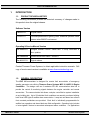
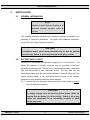
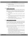
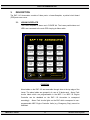
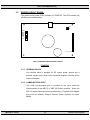
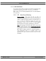
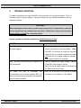
1
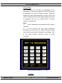
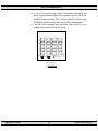
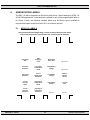
EAP 110 ANNUNCIATOR INSTALLATION, OPERATING & SERVICE MANUAL PM058 Rev 3 14/01/31 th 9087A – 198 Street, Langley, BC Canada V1M 3B1 Telephone (604) 888-0110 Telefax (604) 888-3381 E-Mail: [email protected] www.thomsontechnology.com EAP 110 ANNUNCIATOR CONTENTS 1. INTRODUCTION 4 1.1. PRODUCT REVISION HISTORY 4 1.2. GENERAL DESCRIPTION 4 2. INSTALLATION 6 2.1. GENERAL INFORMATION 6 2.2. BATTERY SUPPLY INPUT 6 2.3. EXTERNAL CONTACT INPUTS 7 2.4. REMOTE COMMUNICATION WIRING 7 2.5. ANNUNCIATOR CONTROL WIRING 8 2.6. ANNUNCIATOR LOCATION/INSTALLATION 8 3. DESCRIPTION 11 3.1. LEXAN FACEPLATE 11 3.2. PRINTED CIRCUIT BOARD 12 4. OPERATING INSTRUCTIONS 19 4.1. SEQUENCE OF OPERATION 19 4.2. CONTROL PUSH-BUTTONS 19 5. PROGRAMMING INSTRUCTIONS 20 6. SPECIFICATIONS 21 7. CONNECTION DIAGRAMS 22 PM058 Rev3 14/01/31 Thomson Power Systems EAP 110 ANNUNCIATOR 8. ANNUNCIATOR LABELS 23 8.1. NFPA 110 LABELS 23 8.2. CSA 282 LABELS 24 8.3. MEC 20 (GROUP 2 FAULT) LABELS 25 8.4. MEC 2 (GROUP 2 FAULT) LABELS 26 9. TROUBLE SHOOTING 27 10. NOTES 28 PM058 Rev3 14/01/31 Thomson Power Systems EAP 110 ANNUNCIATOR 1. INTRODUCTION 1.1. PRODUCT REVISION HISTORY The following information provides an historical summary of changes made to this product since the original release. Software Version 1.0 02/07/31 Original version. 1.1 06/01/17 Corrected phenomena of glowing LEDs. Enhanced operation under extreme noise EMI/RFI environment Operating & Service Manual Version Rev 2 06/01/17 Changed Software version. Added MEC 2 Group information & misc. updates Rev 1 05/05/18 Updated Annunciator labels - Section 8. Rev 0 02/07/31 Original release. Contact Thomson Power Systems, to obtain applicable instruction manuals. Soft copy of most current version is available at www.thomsontechnology.com. 1.2. GENERAL DESCRIPTION The EAP 110 annunciator is designed for remote fault annunciation of emergency standby generator sets utilizing Thomson Power Systems MEC 2 & MEC 20 Engine Controllers. The design uses an 8 conductor RS 422 communication data link to provide the control & monitoring signals between the engine controller and remote annunciator. The communication link allows a simple, cost effective system installation at any building site. Up to 20 individual fault conditions are remotely monitored utilizing both visual LED lights & audible alarm annunciation. Lamp test and alarm horn silence front mounted pushbuttons are provided. Each fault is individually programmable for audible horn operation and alarm labels are field configurable. Operation logic includes a “auto-ringback” feature to annunciate subsequent alarm conditions. For applications PM058 Rev3 14/01/31 4 Thomson Power Systems EAP 110 ANNUNCIATOR requiring additional alarm annunciation from remote sensing contacts, the EAP 110 can accept up to 4 hard wired contact inputs dependant upon the alarm configuration, separate from the Annunciator communication data link. The EAP 110 is DC powered from the same 12 or 24V engine starting battery as the engine controller is connected to. Two EAP 110 annunciators can be interconnected together via the communication link to allow up to 40 remote annunciator points from a single engine controller (consult Thomson Power Systems for further details). The standard features of the EAP 110 meet and exceed all requirements of NFPA 110, NFPA 99 & CSA 282-00 building code standards for Emergency Standby Generator systems. CAUTION contents subject to damage by STATIC ELECTRICITY This equipment contains static-sensitive parts. Please observe the following anti-static precautions at all times when handling this equipment. Failure to observe these precautions may cause equipment failure and/or damage. • Discharge body static charge before handling the equipment (contact a grounded surface and maintain contact while handling the equipment, a grounded wrist strap can/should also be utilized). • Do not touch any components on the printed circuit board with your hands or any other conductive equipment. • Do not place the equipment on or near materials such as Styrofoam, plastic and vinyl. Place the equipment on grounded surfaces and only use an anti-static bag for transporting the equipment. PM058 Rev3 14/01/31 5 Thomson Power Systems EAP 110 ANNUNCIATOR 2. INSTALLATION 2.1. GENERAL INFORMATION NOTE: Installations should be done according to all applicable electrical regulation codes as required. The following installation guidelines are provided for general information only pertaining to typical site installations. For specific site installation information, consult Thomson Power Systems as required. CAUTION!!! All installation and/or service work performed must be done by qualified personnel only. Failure to do so may cause personal injury or death. 2.2. BATTERY SUPPLY INPUT The EAP 110 can operate on any battery supply from 10 to 30 volts DC. The battery DC negative or common conductor must be grounded to the main generator-set frame ground. The EAP 110 is internally protected by a solid state type fuse that protects it from inadvertent shorts. The solid state fuse will automatically reset when the overcurrent condition is removed. Wiring from the engine cranking battery to the annunciator should conform to the following guidelines to avoid possible malfunction and/or damage. 2.2.1. Avoid wiring from the engine starter terminals - wiring should go directly from the engine control panel. CAUTION!!! The battery charger must be turned off before battery cables are removed from the battery (i.e. for servicing). Failure to do so may subject the annunciator to an overvoltage condition in which damage may result. PM058 Rev3 14/01/31 6 Thomson Power Systems EAP 110 ANNUNCIATOR 2.2.2. Wiring from the engine control panel to the annunciator should be two #14 AWG (2.5mm2) wires. 2.2.3. Under noisy environments (i.e. gas engines with high voltage ignitions, etc.), wiring from battery should be a twisted pair of #14 AWG (2.5mm2) wires. 2.3. EXTERNAL CONTACT INPUTS All external contact inputs to the EAP 110 are optically isolated and filtered for protection from noise spikes and transients. Wiring should conform to the following guidelines to avoid possible Annunciator malfunction and/or damage 2.3.1. External contact wires (2 - #14 AWG (2.5mm2) should be run in a separate conduit. 2.3.2. Avoid wiring near AC power cables to prevent pick-up of induced voltages. 2.3.3. An interposing relay may be required if field wiring distance is excessively long (i.e. greater than 100 feet (30m) and/or if a remote contact has a resistance of greater than 5.0 ohms. 2.3.4. The external contacts (if used) must be voltage free (i.e. dry contact). The use of a “powered” contact will damage the Annunciator. 2.4. REMOTE COMMUNICATION WIRING All interconnecting wiring to/from the EAP 110 Annunciator communication port shall utilize #22 AWG (min.) 8 conductor, twisted, shielded cable with RJ45 connectors. The drain (shield) wire must be connected at the Engine Controller end only. Refer to connection diagram in Section 7 for further information. Communication cable from the Annunciators’ com port must be suitably routed to protect it from sources of electrical interference. Guidelines for protection against possible electrical interference are as follows: • Use high quality, 8 conductor shielded cable only with drain wire grounded at the Engine Controller end only. • Route the communication cable at least 3 M (10”) away from sources of electrical noise such as variable speed motor drives, high voltage power conductors, UPS systems, transformers, rectifiers etc. • Use separate, dedicated conduit runs for all communication cables. Do not tightly bundle communication cables together in the conduit. Conduit PM058 Rev3 14/01/31 7 Thomson Power Systems EAP 110 ANNUNCIATOR should be ferromagnetic type near sources of possible electrical interference. The entire length of conduit should be grounded to building earth ground. • When communication cables must cross over low or high voltage AC power conductors, the communication cables must cross at right angles and not in parallel with the conductors. For additional information on protection against electrical interference, contact Thomson Power Systems factory. 2.5. ANNUNCIATOR CONTROL WIRING As a minimum, all control wiring shall conform to the local regulatory authority on electrical installations. Specific wire sizes for typical circuits (of distances up to 1000ft (300m) ⊇) are as follows: 2.5.1. Battery Control Power #14 AWG (2.5mm2) 2.5.2. External Fault Contacts #16 AWG (1.5mm2) 2.5.3. Remote Communication Wiring #22 AWG (0.34mm2) 8 Conductor Shielded Cable ⊇ For distances exceeding 1000 Ft. (300m) consult THOMSON POWER SYSTEMS. 2.6. ANNUNCIATOR LOCATION/INSTALLATION The annunciator is to be mounted indoors in a dirt free, dry location away from extreme heat sources on a building wall at a suitable location for operating personnel. The annunciator is to be mounted using four screws. The annunciator must be mounted within 1000 feet wiring distance from the MEC 20/MEC 2 Engine controller using an 8 conductor shielded cable. The standard annunciator is suitable for surface mounting as shown in FIGURE #1. The annunciator is available with an optional adapter plate for flush mounting application as shown in FIGURE #2. Assembly details for the flush mounting adapter are shown in FIGURE #3. PM058 Rev3 14/01/31 8 Thomson Power Systems EAP 110 ANNUNCIATOR EAP 110 Rear Cover 6.0" 4.0" 6.0" 1.0" 4 Rear Cover Mounting Holes 3/16" DIAMETER 4.0" 1.0" EAP 110 SURFACE MOUNTING Enclosure Depth (from front faceplate) = 3.0" G:\ENGINEER\PRODUCTS\EAP110 Surface Mount.VSD FIGURE #1 Flush Mount Adapter Plate 7.0" 0.25" EAP 110 Rear Cover Cutout 6.50" 7.0" (for 6" x 6" clearance) 6.125" 4 Faceplate Mounting Holes 3/16" DIAMETER 6.125" 6.50" 0.25" EAP 110 FLUSH MOUNTING Enclosure Depth (from front faceplate) = 3.0" G:\ENGINEER\PRODUCTS\EAP110 Flush Mount.VSD FIGURE #2 PM058 Rev3 14/01/31 9 Thomson Power Systems EAP 110 ANNUNCIATOR Wall Edge (Flush Mounting) Wall Edge (Surface Mounting) 6.0" EAP 110 Rear Cover 3.0" EAP Flush Mounting Plate (optional) EAP Front Faceplate EAP 110 Assembly (Side View) G:\ENGINEER\PRODUCTS\EAP110 Assembly.VSD FIGURE #3 PM058 Rev3 14/01/31 10 Thomson Power Systems EAP 110 ANNUNCIATOR 3. DESCRIPTION The EAP 110 Annunciator consists of three parts: a Lexan/faceplate, a printed circuit board (PCB) and a rear cover. 3.1. LEXAN FACEPLATE The Lexan faceplate is shown as in FIGURE #4. The Lexan push-buttons and LED’s are connected to the main PCB via plug-in ribbon cable. EAP 110 Annunciator Emergency Stop EPS Supplying Load EPS Switch Not in Auto (Digital Fault #1) Overcrank Shutdown Low Engine Temperature Alarm Weak Battery Voltage (Digital Fault #2) Overspeed Shutdown Loss of Speed Signal Shutdown Low Battery Voltage Battery Charger AC Fail Low Oil Pressure Alarm High Engine Temperature Alarm High Battery Voltage Low Oil Pressure Shutdown High Engine Temperature Shutdown Alarm Silence Spare Spare (Digital Fault #3) Low Fuel Level (Digital Fault #4) Spare Spare (External Input #2) (External Input #1) Lamp Test Power On Communication Fail FIGURE #4 Alarm labels on the EAP 110 are removable through slots at the top edge of the Lexan. The alarm labels are grouped in 4 rows of 5 labels each. Alarm Fault circuits labels which are programmable in the MEC 2 or MEC 20 Engine Controller can be relabeled on the EAP 110 Annuciator to correspond accordingly. Alarm Fault circuits lights on the EAP which correspond to non- programmable MEC Engine Controller faults (e.g. Emergency Stop) cannot be relabeled. PM058 Rev3 14/01/31 11 Thomson Power Systems EAP 110 ANNUNCIATOR 3.2. PRINTED CIRCUIT BOARD The printed circuit board (PCB) is shown in FIGURE #5. The PCB contains the following user interface items: J1 RJ45 JP3 JP2 Ext 4 Ext 3 Ext 2 Ext 1 GRD BB+ Lexan Connector EAP 110 PRINTED CIRCUIT BOARD LAYOUT FIGURE #5 3.2.1. TERMINAL BLOCK One terminal block is provided for DC control power, ground and 4 external contact inputs. Refer to the connection diagram in section #7 for further information. 3.2.2. COMMUNICATION PORT One RJ45 communication port is provided on the circuit board for interconnection to the MEC 2 or MEC 20 Engine controller. When two EAP 110 annunciators are to be interconnected, a T-splitter RJ45 adapter plug must be installed. Contact Thomson Power Systems for further details. PM058 Rev3 14/01/31 12 Thomson Power Systems EAP 110 ANNUNCIATOR 3.2.3. ALARM ADDRESSING Two jumpers (JP2 & JP3) are located on the PCB for programming the specific alarm addressing on the EAP 110 as shown in FIGURE #5. Note: Jumper JP1 is for Factory programming use. For normal operation, JP1 must be On. 3.2.3.1. JP2 Alarm Group Addressing Group 1 Faults: With jumper JP2 OFF, the EAP 110 addressing will be programmed to match the standard faults on a MEC 2 or MEC 20 Engine controller as required NFPA 110 level 2 & CSA 282. FIGURE #6 Indicates the specific fault addressing for Group 1 faults. The EAP 110 will be supplied from the factory set for Group 1 addressing (i.e. JP2 OFF). Note: LED Fault light “EPS SUPPLYING LOAD” is driven from the MEC 2/MEC 20 engine controller Programmable output #5. Programmable Output #5 must therefore be programmed in the MEC 2/MEC 20 engine controller for “ENGINE RUNNING” or “EPS SUPPLYING LOAD” as is available. Refer to the applicable MEC engine controller instruction manual for further information. PM058 Rev3 14/01/31 13 Thomson Power Systems EAP 110 ANNUNCIATOR EAP 110 Annunciator Emergency Stop EPS Supplying Load EPS Switch Not in Auto (Digital Fault #1) Overcrank Shutdown Low Engine Temperature Alarm Weak Battery Voltage (Digital Fault #2) Overspeed Shutdown Loss of Speed Signal Shutdown Low Battery Voltage Battery Charger AC Fail Low Oil Pressure Alarm High Engine Temperature Alarm High Battery Voltage Low Oil Pressure Shutdown High Engine Temperature Shutdown (or External Input #4) (or External Input #3) Alarm Silence Lamp Test Spare Spare (Digital Fault #3) Low Fuel Level (Digital Fault #4) Spare Spare (External Input #2) (External Input #1) Power On Communication Fail Group 1 Alarm Addressing DATE 06/01/18 3:16 PM G:\ENGINEER\PRODUCTS\EAP110\EAP110 LEXAN GROUP 1.VSD FIGURE #6 PM058 Rev3 14/01/31 14 Thomson Power Systems EAP 110 ANNUNCIATOR Group 2 Faults With jumper JP2 ON, the EAP 110 addressing will be programmed to match the 20 additional faults circuits as may be programmed on a MEC 20 Engine controller. FIGURE #7 Indicates the specific fault addressing for Group 2 faults. Fault names for digital faults #5-12 and programmable output #6 will be dependent upon how the connected MEC 20 Engine Controller is programmed. Notes: 1) Group 2 addressing is not applicable for MEC 2 Engine Controllers 2) Low Oil Pressure and High Engine temperature Shutdowns are driven from the engine controllers Analog engine sender input devices if programmed accordingly. Refer to the engine controller instruction manual for further information. EAP 110 Annunciator Under Voltage Shutdown Progr. #6 Over Voltage Shutdown Spare (Digital Fault #5) Under Frequency Shutdown Over Frequency Shutdown Spare Spare (Digital Fault #7) (Digital Fault #6) Spare Spare (Digital Fault #12) (Digital Fault #8) Over Current Alarm Spare (Digital Fault #9) High Engine Temperature Shutdown Spare (Digital Fault #10) Low Oil Pressure Shutdown Spare (Digital Fault #11) Spare Spare Spare Spare (External Input #4) (External Input #3) (External Input #2) (External Input #1) Alarm Silence Lamp Test Power On Communication Fail Group 2 Alarm Addressing (MEC 20) DATE 06/01/24 G:\ENGINEER\PRODUCTS\EAP110\EAP110 LEXAN GROUP 2.VSD FIGURE #7 PM058 Rev3 14/01/31 15 Thomson Power Systems EAP 110 ANNUNCIATOR PM058 Rev3 14/01/31 16 Thomson Power Systems EAP 110 ANNUNCIATOR EAP 110 Annunciator Under Voltage Shutdown Progr. #6 Over Voltage Shutdown Over Current Alarm Under Frequency Shutdown Over Frequency Shutdown High Engine Temperature Shutdown Low Oil Pressure Shutdown Spare Spare Spare Spare (External Input #4) (External Input #3) (External Input #2) (External Input #1) Alarm Silence Lamp Test Power On Communication Fail Group 2 Alarm Addressing (MEC 2) DATE 06/01/24 G:\ENGINEER\PRODUCTS\EAP110\EAP110 LEXAN GROUP 2 MEC2..VSD FIGURE #8 3.2.3.2. JP3 Low Oil Pressure & High Engine Temp Shutdown Fault Addressing (Group 1 Addressing): Fault LED lights D19 & D20 as shown in FIGURE #8 may be programmed for input from either two different alarm address inputs when the annunciator is set for group 1 addressing. With JP3 jumper ON, the EAP 110 Fault LED lights D19 & D20 will be addressed to external input contacts #4 & #3 as connected to the EAP 110 terminal blocks. With JP3 jumper OFF, the EAP 110 Fault LED lights D19 & D20 will be addressed to the MEC 2 or MEC 20 Engine controller Analog Shutdown circuits for Low Oil Pressure (LOP2) & High Engine Temperature (HET2) respectively as programmed. If these faults are not programmed on the MEC Engine Controllers, these fault LEDs will not be active. Refer to the applicable engine controller instruction manual for further information. Notes: PM058 Rev3 14/01/31 17 Thomson Power Systems EAP 110 ANNUNCIATOR 1) If Low Oil Pressure & High Engine Temperature shutdowns are driven by the standard Digital Fault contacts (Inputs #1 & #2) on the MEC Engine controller, EAP 110 fault Lights D11 & D12 as per FIGURE #8 will be activated when set for Group 1 addressing. 2) The EAP will be supplied from the factory with JP3 OFF (i.e. to address to the analog LOP & HET faults) D1 D16 D15 D11 D2 D8 D5 D12 D3 D4 D6 D13 D10 D9 D7 D14 D19 D20 D18 D17 S1 S2 Alarm Silence D22 Lamp Test D21 Power On Communication Fail EAP 110 LED Numbering FIGURE #9 PM058 Rev3 14/01/31 18 Thomson Power Systems EAP 110 ANNUNCIATOR 4. OPERATING INSTRUCTIONS 4.1. SEQUENCE OF OPERATION When the EAP 110 is energized and is interconnected to an operating system, it will display any faults which are currently active on the MEC 2 or MEC 20 Engine controller. Any new faults will be displayed by a flashing LED light and the internal alarm horn will sound. Once the alarm has been acknowledged via “ALARM SILENCE” push-button, the horn will be silenced and the LED light will remain on continuously. Any subsequent alarms will cause the horn to sound again and new fault LED to flash. The activated LED lights will remain on until the fault condition has been reset at the engine controller. If the EAP 110 is also connected to the 4 possible external contact input circuits, these faults will be activated in the same sequence by the remote contacts closing or opening upon a fault. Remote contacts close to initiate an alarm fault. 4.2. CONTROL PUSH-BUTTONS The following control push-buttons are located on the front faceplate keypad. 4.2.1. ALARM SILENCE FUNCTION To initiate an alarm (horn) silence function, press the “ALARM SILENCE” pushbutton. Should subsequent faults be activated, the alarm horn will resound which will require another alarm silence action. 4.2.2. LAMP TEST A lamp test feature is provided to test all LED annuciator lights. To activate the lamp test feature, press the “LAMP TEST” pushbutton. PM058 Rev3 14/01/31 19 Thomson Power Systems EAP 110 ANNUNCIATOR 5. PROGRAMMING INSTRUCTIONS The EAP 110’s audible horn may be programmed individually per alarm fault circuit. The EAP 110 will be supplied from the factory with the horn “ENABLED” for all alarm circuits. To enter the programming mode, follow the procedure as shown: NOTE: The EAP 110 will not provide alarm annunciation during the program mode. 1. Simultaneously press and hold both ALARM SILENCE & LAMP TEST pushbuttons down for 3 seconds, then release. 2. All LED’s illuminated will indicate that they are programmed as the Horn Disabled. All LED’s which are not illuminated indicate that they are programmed as the Horn-Enabled. The factory default setting is HornEnabled. 3. To program LED D1’s horn function, momentarily press the LAMP TEST push-button. The flashing rate of the LED will change to reflect the different settings. The two different flashing rates indicate the following operation: Long Pulse On, Short Pulse Off = Horn Disabled Short Pulse On, Long Pulse Off = Horn Enabled 4. Once the desired operation is selected for D1, momentarily press the ALARM SILENCE push-button to advance the programming point to the next LED and repeat process 3. 5. This process can be completed for all LED lights D2-D22. Once the last LED is selected (D22), the programming mode will be terminated once the ALARM SILENCE push-button is momentarily pressed. Note: the programming mode will be automatically terminated following no key presses in approximately 30 seconds. Once the programming mode is terminated, the EAP 110 will resume normal operation. PM058 Rev3 14/01/31 20 Thomson Power Systems EAP 110 ANNUNCIATOR 6. SPECIFICATIONS SUPPLY VOLTAGE 12V or 24V nominal (+- 20%), negative ground SUPPLY CURRENT 100 ma (maximum), (+- 20%) COMMUNICATION PORT RS 422, 4.8 KBaud, Thomson Power Systems T-Net Protocol to MEC 2/MEC 20 8 conductor #22 AWG (min) Shielded/Twisted cable (1000 ft Max), Plug-in RJ45 Connector EXTERNAL CONTACT INPUT Close to DC Negative TEMPERATURE RANGE -40 C to +50 Deg C ENVIRONMENTAL Faceplate NEMA 12, Rear Enclosure NEMA 1 DIMENSIONS 6.0” W x 6.0” H x 3.0” D (Flush mount adapter option (7.0” w x 7.0” H) MOUNTING Surface Mount (Standard), Flush-mount (Optional) Rear Enclosure conduit box c/w Qty 8 ½” knockouts Specifications subject to change without notice. PM058 Rev3 14/01/31 21 Thomson Power Systems EAP 110 ANNUNCIATOR 7. CONNECTION DIAGRAMS EAP 110 Annunciator GRD Communication Cable** Ext 1 Ext 2 Ext 3 Ext 4 MEC 2/20 Engine Controller J6 J1 Expansion Port No Connection J7 Com Port 1000' maximum cable length B+ B- B+ B- External Alarm Sensing contacts (optional use as required) + - **8 conductor Shielded Twisted Cable c/w RJ45 connectors. Communication cable wiring must be suitably routed to protect it from sources of electrical interference. Refer to section 2.4. of this manual for further information. J1 1000' maximum cable length (total from controller) Ext 4 Ext 3 Ext 2 Ext 1 EAP 110 Annunciator (Group 2) B+ B- Power and contacts to be connected as shown below Ext 4 Ext 3 Ext 2 Ext 1 EAP 110 Annunciator (Group 1) Communication Cables** J1 J6 GRD Expansion Port Optional RJ45 Connector Splitter (required for 2 x EAP 110) B+ B- No Connection MEC 2/20 Engine Controller J7 Com Port B+ B- External Alarm Sensing contacts (optional use as required) + - **8 conductor Shielded Tw isted Cable c/w RJ45 connectors. Communication cable w iring must be suitably routed to protect it from sources of electrical interference. Refer to instruction manual for further information. PM058 Rev3 14/01/31 12-24V Engine Cranking Battery 22 12-24V Engine Cranking Battery Thomson Power Systems EAP 110 ANNUNCIATOR 8. ANNUNCIATOR LABELS The EAP 110 will be supplied from the factory with Group 1 alarm labeling for NFPA 110 & CSA 282 applications. If new labels are required for any of the programmable faults or for Group 2 faults, the following standard labels may be Photo copied, modified as required and maybe inserted into the EAP 110 Lexan as required. 8.1. NFPA 110 LABELS Using xacto knife and straight edge, cut into 4 vertical strips at crop marks. Insert each strip into the correct lexan slot, centering text in windows. EPS Supplying Load EPS Switch Not In Auto Low Engine Temperature Alarm Weak Battery Voltage Overspeed Shutdown Loss of Speed Signal Shutdown Low Battery Voltage Battery Charger AC Fail Low Oil Pressure Alarm High Engine Temperature Alarm High Battery Voltage Low Fuel Level Low Oil Pressure Shutdown High Engine Temperature Shutdown (External 2) (External 1) Emergency Stop Overcrank Shutdown PM058 Rev3 14/01/31 (Digital Fault 1) (Digital Fault 2) 23 Thomson Power Systems EAP 110 ANNUNCIATOR 8.2. CSA 282 LABELS Using xacto knife and straight edge, cut into 4 vertical strips at crop marks. Insert each strip into the correct lexan slot, centering text in windows. EPS Supplying Load EPS Switch Not In Auto Low Engine Temperature Alarm Weak Battery Voltage Overspeed Shutdown Loss of Speed Signal Shutdown Low Battery Voltage Low Coolant Level Shutdown Low Oil Pressure Alarm High Engine Temperature Alarm High Battery Voltage Low Fuel Level Low Oil Pressure Shutdown High Engine Temperature Shutdown (External 2) (External 1) Emergency Stop Overcrank Shutdown PM058 Rev3 14/01/31 (Digital Fault 1) (Digital Fault 2) 24 Thomson Power Systems EAP 110 ANNUNCIATOR 8.3. MEC 20 (GROUP 2 FAULT) LABELS Using xacto knife and straight edge, cut into 4 vertical strips at crop marks. Insert each strip into the correct lexan slot, centering text in windows. Under Voltage Shutdown Over Voltage Shutdown Under Frequency Shutdown PM058 Rev3 14/01/31 (Progr. #6) (Digital Fault 12) Over Current Alarm (Digital Fault 5) Over Frequency Shutdown (Digital Fault7) (Digital Fault 6) (External 4) (External 3) High Engine Temperature Shutdown Low Oil Pressure Shutdown (External 2) 25 (Digital Fault 8) (Digital Fault 9) (Digital Fault 10) (Digital Fault 11) (External 1) Thomson Power Systems EAP 110 ANNUNCIATOR 8.4. MEC 2 (GROUP 2 FAULT) LABELS Using xacto knife and straight edge, cut into 4 vertical strips at crop marks. Insert each strip into the correct lexan slot, centering text in windows. Under Voltage Shutdown (Progr. #6) Over Current Alarm Over Voltage Shutdown Under Frequency Shutdown Over Frequency Shutdown High Engine Temperature Shutdown Low Oil Pressure Shutdown (External 4) PM058 Rev3 14/01/31 (External 3) (External 2) 26 (External 1) Thomson Power Systems EAP 110 ANNUNCIATOR 9. TROUBLE SHOOTING A number of problems can cause the EAP 110 Annunciator not to function properly. Refer to the following list of typical problems. Consult the factory for any detailed information or for any problems not listed. CAUTION!!! Before opening the annunciator to perform any service task, it is imperative to isolate the control system from any possible source of power. Failure to do so may result in serious personal injury or death due to electrical shock. Service procedures must be undertaken by qualified personnel only! SYMPTOM CORRECTIVE ACTION Annunciator does not power up even with correct - Check that there are no wiring errors/short DC power applied circuits connected to the Annunciator. Note: The EAP 110 contains an electronic fuse that triggers upon an overload condition and does not reset until the supply voltage is removed, and overload condition is corrected. Lamp Test does not activate any LED lights on the - Check if adequate DC supply voltage is applied EAP Annunciator to the EAP & the polarity is correct. - Verify the Lexan ribbon cable is connected to the EAP printed circuit board. DC Power On LED is illuminated and - Verify JP1 on the EAP 110 PCB has a jumper Communication link is correct however EAP 110 connector on it (Jumper On = Run Mode) does not respond to any activated fault conditions from the Engine controller. PM058 Rev3 14/01/31 27 Thomson Power Systems EAP 110 ANNUNCIATOR SYMPTOM CORRECTIVE ACTION Communication Fail Light is on - Check the communication cable is connected properly on both the EAP 110 end and at the MEC 2/MEC 20 engine controller end. Notes: 1) On MEC 20 applications, ensure communication cable is connected to the MEC Expansion Port (J6) and not the communication port (J7) 2) MEC 2 applications require software version 1.2 (or greater) software version for correct EAP 110 operation. Annunciator fault lights do not correspond to same - Verify the EAP 110 has the correct alarm group faults on the MEC Engine Controller addressing jumpers installed. Refer to section 3.2.3 for further information. 10. NOTES PM058 Rev3 14/01/31 28 Thomson Power Systems