1
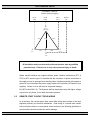
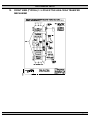
TS 870
AUTOMATIC TRANSFER SWITCHES
INSTALLATION, OPERATING &
SERVICE MANUAL
PM062 Rev 0 04/11/19
9087A – 198th Street, Langley, BC Canada V1M 3B1
Telephone (604) 888-0110
Telefax (604) 888-3381
E-Mail: [email protected]
www.thomsontechnology.com
TS 870 TRANSFER SWITCH
TABLE OF CONTENTS
1.
PRODUCT REVISION HISTORY
1
2.
EQUIPMENT STORAGE
1
3.
NOTES TO INSTALLER
1
3.1.
UPSTREAM CIRCUIT PROTECTIVE DEVICES/ELECTRICAL CONNECTIONS
2
3.2.
TRANSFER SWITCHES WITH INTEGRAL OVER CURRENT PROTECTION
2
3.3.
TRANSFER SWITCHES WITH MULTI-TAP VOLTAGE CAPABILITY
3
3.4.
SYSTEM PHASING-HIGH LEG DELTA SYSTEMS
3
3.5.
REMOTE START CONTACT FIELD WIRING
4
3.6.
DIELECTRIC TESTING
5
3.7.
INSTALLATION OF OPEN TYPE TRANSFER SWITCHES
5
4.
5.
6.
GENERAL DESCRIPTION
5
4.1.
PRODUCT MODEL CODE
6
4.2.
TYPICAL COMMISSIONING PROCEDURES
7
GENERAL THEORY OF OPERATION
8
5.1.
STANDARD AUTOMATIC TRANSFER SWITCH
8
5.2.
SERVICE ENTRANCE AUTOMATIC TRANSFER SWITCH
9
5.3.
TEST MODES
12
OVER CURRENT PROTECTION
12
6.1.
STANDARD TS 870 AUTOMATIC TRANSFER SWITCH
12
6.2.
OPTIONAL TS 870 AUTOMATIC TRANSFER SWITCH WITH INTEGRAL OVER
CURRENT PROTECTION
13
7.
GENERAL NOTES ON SERVICING ATS MECHANISM
13
8.
TRANSFER SWITCH MECHANISM – 100A-250 AMP
14
8.1.
15
9.
MANUAL OPERATION
TRANSFER SWITCH MECHANISM – 400A - 1200 AMP
PM062 REV 0 04/11/19
15
Thomson Technology
TS 870 TRANSFER SWITCH
9.1.
MANUAL OPERATION
16
10.
RECOMMENDED MAINTENANCE
16
11.
FRONT VIEW (TYPICAL) 3 / 4 POLE 100A-250A TRANSFER MECHANISM
17
12.
FRONT VIEW (TYPICAL) 3 / 4 POLE STYLE 400A-1200A TRANSFER MECHANISM
18
13.
CONNECTION CONFIGURATION OPTIONS
19
14.
CABLE TERMINAL INFORMATION
20
15.
REQUIREMENTS FOR UPSTREAM CIRCUIT PROTECTIVE DEVICES
20
16.
GROUND FAULT SITE TEST REQUIREMENTS
21
16.1.
21
PERFORMANCE TEST
17.
TROUBLESHOOTING
22
18.
REPLACEMENT PARTS
25
19.
PRODUCT RETURN POLICY
26
20.
NOTES
27
21.
PERFORMANCE TEST FORM
28
PM062 REV 0 04/11/19
Thomson Technology
TS 870 TRANSFER SWITCH
1.
PRODUCT REVISION HISTORY
The following information provides an historical summary of changes made to this product since the
original release.
Operating & Service Manual Version
Rev 0 04/11/19
Original release.
Contact Thomson Technology, to obtain applicable instruction manuals or if in doubt about
any matter relating to installation, operation or maintenance. Soft copy of the most current
version is available at www.thomsontechnology.com.
NOTE: All information contained in this manual is for reference only and is subject
to change without notice.
2.
EQUIPMENT STORAGE
The following procedures are required for correct storage of the transfer switch prior to installation.
CAUTION!!!
Failure to store equipment as specified may cause damage and void warranty.
Before storing, unpack sufficiently to check for concealed damage. If concealed damage is
found, notify Thomson Technology and the Carrier immediately.
Repack with the original, or equivalent packing materials. Protect from physical damage. Do
not stack.
Store indoors in a clean, dry, well ventilated area free of corrosive agents including fumes,
salt and concrete/cement dust. Apply heat as necessary to prevent condensation.
The following storage temperature and humidity must be maintained: -20 to +70 °Celsius,
95% Humidity non-condensing.
3.
NOTES TO INSTALLER
Before opening the transfer switch enclosure to perform any service task, or to manually transfer the
mechanism, it is imperative to isolate the transfer switch from any possible source of power. Failure
to do so may result in serious personal injury or death due to electrical shock.
PM062 REV 0 04/11/19
1
Thomson Technology
TS 870 TRANSFER SWITCH
CAUTION!!!
All installation and/or service work performed must be done by qualified
personnel only. Failure to do so may cause personal injury or death.
3.1.
UPSTREAM CIRCUIT PROTECTIVE DEVICES/ELECTRICAL
CONNECTIONS
To ensure satisfactory installation of this equipment be sure to observe "Cable Terminal
Information” regarding power cable connection tightness and "Requirements for Upstream
Circuit Protective Devices" located in this manual.
All mechanical and electrical connections must be checked for tightness prior to placing this
equipment in service to ensure proper operation and to validate applicable warranty
coverage.
3.2.
TRANSFER SWITCHES WITH INTEGRAL OVER CURRENT PROTECTION
For models of transfer switch with integral over current protection, the over current protection
must be set prior to operation. The equipment will be shipped from the factory with a longtime
current
setting
of
100%
(of
the
equipment
rating)
and
maximum
short-
time/instantaneous current and time delay settings.
WARNING!
Do Not Energize this equipment until
device settings have been verified to
ensure
proper
coordination.
system
protection
&
Failure to do so may
result in equipment failure.
Refer to Section 5.2.2 of this manual for additional information on operation of the Transfer
switch following an over current trip condition.
Refer to information supplied with the transfer switch documentation package for adjustment
procedures on the power switching units over current protection trip unit. Contact the factory
if any additional information is required.
PM062 REV 0 04/11/19
2
Thomson Technology
TS 870 TRANSFER SWITCH
3.3.
TRANSFER SWITCHES WITH MULTI-TAP VOLTAGE CAPABILITY
If the transfer switch has programmable multi-tap voltage capability (i.e. ATS Model Code
with Voltage Code “Y”), confirm the transfer switch has been configured for the correct
system voltage prior to installation.
WARNING!
Failure to confirm and match transfer
switch voltage with the system voltage
could cause serious equipment damage.
The voltage selections and connections are shown on the engineered drawings attached to
each transfer switch. The factory default settings will be indicated on the calibration label
attached on the inside of the enclosure door (supplied loose on open style models). A blank
label is included to record the applicable settings if the configuration is changed from the
factory default settings.
To change the transfer switch configuration the following must be accomplished:
•
Change voltage taps on potential transformers (PT’s) to correct system voltage (refer
to drawings)
•
Change TSC 80 programming for nominal system voltage. Refer to Section 4 of the
TSC 80 instruction manual (PM063) for further information.
•
Once the PT voltage taps and TSC 80 has been re-programmed to correct operating
voltage, the “control circuit isolation plug” on the mechanism, may be reconnected,
prior to voltage energization.
3.4.
SYSTEM PHASING-HIGH LEG DELTA SYSTEMS
For systems using high leg delta 240V 3 phase 4 wire systems, connection of supply
conductors must have the correct phasing as shown below.
WARNING
Failure
to
match
correct
system
phasing will result in serious damage
to the TSC 80 controller.
PM062 REV 0 04/11/19
3
Thomson Technology
TS 870 TRANSFER SWITCH
Autom atic Transfer
Switch (Utility Supply)
PH A
(UA)
PH B
(UB)
PH C
(UC)
Neural
(N)
B
(Orange)
(High Leg)
240V
A
208V
120V
240V
120V
(Red)
C
(Yellow)
N
(W hite)
CAUTION!!!
All installation and/or service work performed must be done by qualified
personnel only. Failure to do so may cause personal injury or death.
Where transfer switches are supplied without power isolation transformers (PT1 &
PT2) for ATS control logic it is essential that the orientation of phase conductors of
the supply source be arranged such that the phase of highest potential with respect to
ground is not connected to the power supply inputs to the controller (A Phase for both
supplies). Failure to do so will result in equipment damage.
Per NEC Article 384-3 (f) “The B phase shall be that phase having the higher voltage
to ground on a 3-phase, 4-wire delta connected systems.”
3.5.
REMOTE START CONTACT FIELD WIRING
As a minimum, the remote engine start control field wiring shall conform to the local
regulatory authority on electrical installations. Field wiring of a remote start contact
from a transfer switch to a control panel should conform to the following guidelines to
avoid possible controller malfunction and/or damage.
PM062 REV 0 04/11/19
4
Thomson Technology
TS 870 TRANSFER SWITCH
3.5.1. Minimum #14 AWG (2.5mm2) wire size shall be used for distances up to 100ft
(30m)1). For distances exceeding 100 ft. (30m) consult Thomson Technology
3.5.2. Remote start contact wires should be run in a separate conduit.
3.5.3. Avoid wiring near AC power cables to prevent pick-up of induced voltages.
3.5.4. An interposing relay may be required if field-wiring distance is excessively
long (i.e. greater than 100 feet (30m)) and/or if a remote contact has a
resistance of greater than 5.0 ohms.
3.5.5. The remote start contact must be voltage free (i.e. dry contact). The use of a
“powered” contact will damage the transfer controller.
3.6.
DIELECTRIC TESTING
Do not perform any high voltage dielectric testing on the transfer switch with the TSC
80 controller connected into the circuit as serious damage will occur to the controller.
All AC control fuses or control circuit isolation plugs connected to the TSC 80 must be
removed if high voltage dielectric testing is performed on the transfer switch.
3.7.
INSTALLATION OF OPEN TYPE TRANSFER SWITCHES
Please refer to the factory for additional information.
4.
GENERAL DESCRIPTION
Thomson Technology TS 870 series of Automatic Transfer Switches employ two mechanically
interlocked enclosed contact power switching units and a microprocessor based controller to
automatically transfer system load to a generator supply in the event of a utility supply failure.
System load is then automatically re-transferred back to the utility supply following restoration of the
utility power source to within normal operating limits.
The standard TS 870 series Automatic Transfer Switch is rated for 100% system load and requires
upstream over current protection. The TS 870 Automatic Transfer Switch may be supplied with
optional integral over current protection within the enclosed contact power switching units for
applications such as Service Entrance Rated equipment. Refer to Section 6 of this manual for
detailed information on over current protection.
The TS 870 series transfer switches use a type TSC 80 microprocessor based controller which
provides all necessary control functions for fully automatic operation. The TSC 80 controller is
mounted on the door of the transfer switch enclosure and operating status is shown via LED lights.
PM062 REV 0 04/11/19
5
Thomson Technology
TS 870 TRANSFER SWITCH
For further information on the TSC 80 Transfer Controller, refer to separate instruction manual
PM063.
The power switching devices used for the Utility and Generator sources are operated by an
electrically driven motor mechanism in the transfer switch. The transfer switch motor utilizes the
power from the source to which the electrical load is being transferred. The mechanism provides a
positive mechanical interlock to prevent both power switching units from being closed at the same
time, which allows an interrupted “break-before-make” transfer sequence. The TSC 80 transfer
controller provides a standard neutral position delay timer to allow adequate voltage decay during
transfer operation to prevent out of phase transfers.
Note: For the purpose of this manual, the following standard nomenclature is utilized:
•
Utility: to indicate the source of primary power
•
Generator: to indicate the source of standby power
•
Power switching device: to indicate the transfer switch power switching device
4.1.
PRODUCT MODEL CODE
The type of TS 870 series transfer switch supplied is identified by way of a 21 digit product
code which appears on the equipment rating plate (MODEL) on the door of the transfer
switch, and on the transfer switch drawings. The model code structure and definitions are as
follows:
PM062 REV 0 04/11/19
6
Thomson Technology
TS 870 TRANSFER SWITCH
4.2.
TYPICAL COMMISSIONING PROCEDURES
CAUTION:
Commissioning procedures must be performed by qualified
personnel only.
Ensure the Automatic Transfer Switch
(ATS) Isolation Plug is disconnected prior to energizing the
supply sources.
Manually place the transfer switch
mechanism in the neutral position prior to applying power.
Failure to do so may result in equipment failure or personal
injury.
Note: The TYPICAL AUTOMATIC TRANSFER SWITCH COMMISSIONING PROCEDURES
MODEL SERIES TS 870 (attached as “Appendix A ”) is provided for general information
PM062 REV 0 04/11/19
7
Thomson Technology
TS 870 TRANSFER SWITCH
only pertaining to typical site installations and applications. Contact Thomson Technology for
further information as may be required.
Note: An optional hand held, plug-in Service Display Module (SDM) is available for the TSC
80 Transfer Controller. The SDM module provides an LCD screen to display additional
detailed information on the operation and settings of the TSC 80 controller for simplified
servicing/trouble shooting procedures. For detailed information, refer to the separate SDM
module instruction manual (PM065).
5.
GENERAL THEORY OF OPERATION
5.1.
STANDARD AUTOMATIC TRANSFER SWITCH
5.1.1. NORMAL OPERATION
When utility supply voltage drops below a preset nominal value (adjustable from 70%
to 100% of nominal) on any phase, an engine start delay circuit will be initiated and
the transfer to utility supply signal will be removed (i.e. contact opening). Following
expiry of the engine start delay period (adjustable from 0 to 60 sec.) an engine start
signal (contact closure) will be given.
Once the engine starts, the transfer switch controller will monitor the generator
voltage and frequency levels. Once the generator voltage and frequency rises above
preset values (adjustable from 70% to 95% of nominal), the engine warmup timer will
be initiated.
Once the warmup timer expires (adjustable from 0 to 60 sec.), the
Transfer to Generator Supply signal (contact closure) will be given to the transfer
switch mechanism. The load will then transfer from the utility supply to the generator
supply via the motor driven mechanism.
The generator will continue to supply the load until the utility supply has returned.
The retransfer sequence is completed as follows: when the utility supply voltage is
restored to above the preset values (adjustable from 70% to 95% of nominal) on all
phases, a transfer return delay circuit will be initiated. Following expiry of the Utility
Return Timer (adjustable from 0 to 30 min.), the Transfer to Generator Supply signal
will be removed (contact opening), then the Transfer to Utility Supply signal (contact
closure) will be given to the transfer switch mechanism. The load will then retransfer
the load from the generator supply back to the utility supply.
Note: A neutral delay
timer circuit will delay the transfer sequence in the neutral position (i.e. both power
PM062 REV 0 04/11/19
8
Thomson Technology
TS 870 TRANSFER SWITCH
switching devices open) until the neutral time delay period expires (adjustable from 0
to 60 sec.).
An engine cooldown timer circuit will be initiated once the load is transferred from the
generator supply. Following expiry of the cooldown delay period (adjustable from 0 to
30 min.), the engine start signal will be removed (contact opening) to initiate stopping
of the generator set.
5.2.
SERVICE ENTRANCE AUTOMATIC TRANSFER SWITCH
Note: This applies only to service entrance transfer switches
5.2.1. NORMAL OPERATION
Under normal conditions, the load is energized from the utility supply through the
closed utility transfer power switching device. If the utility power fails, the generator
will start and the load will be re-energized via the closed generator transfer power
switching device.
In the normal operating mode, the Service Disconnect switch shall be in the
“energized” position.
5.2.2. OVER CURRENT TRIP
Should the utility power switching device trip open due to an over current condition,
TSC 80 transfer controller will initiate an engine start signal and will permit transfer of
the load to the generator supply. The utility source will be locked out and the load will
remain on the generator supply until the TSC 80 alarm signal is manually reset.
Refer to the TSC 80 Instruction Manual for further details on Transfer Fail operation.
Should the generator power switching device trip open due to an over current
condition, TSC 80 transfer controller will initiate transfer of the load to the utility
supply. The generator source will be locked out and the load will remain on the utility
supply until the TSC 80 alarm signal is manually reset.
5.2.3. SERVICE DISCONNECT PROCEDURE
To perform a service disconnect (i.e. to disconnect the utility and generator supplies),
the following procedure is required:
1. Move the "Service Disconnect" control switch located on the door of the transfer
switch to the "Disconnected" position.
PM062 REV 0 04/11/19
9
Thomson Technology
TS 870 TRANSFER SWITCH
2. Verify that the "Service Disconnected" pilot light is illuminated.
If the Light is
illuminated, the service has been successfully disconnected and it is safe to perform
any maintenance procedures as required. In this condition, the transfer switch is in
the neutral position, with both utility and transfer power switching devices open. The
transfer switch will remain in this condition, regardless of condition of the utility and
generator supplies (i.e. if the utility power fails, the generator will not receive a start
condition, nor will the transfer switch move to the generator position). If the Light is
not illuminated, further procedures are required (refer to the following procedure #4).
3. Attach safety lockout padlock to the "Service Disconnect" control switch to prevent
unauthorized change in operating condition and verify transfer switch door is locked
closed. If the door is not locked, turn and remove door key.
4. If the "Service Disconnected" pilot light is not illuminated, the service will not have
been successfully disconnected and it is therefore not safe to perform any
maintenance until the following additional procedures are performed:
WARNING!
Qualified personnel must undertake the following
procedures only!
Failure to do so may result in
serious personal injury or death due to electrical
shock.
•
Open the door to the transfer switch using a suitable tool and opening the door
lock with the key.
•
Visually inspect the actual position of the transfer switch mechanism.
If the
position of the transfer switch mechanism is clearly in the "neutral position", the
service has been successfully disconnected.
Note: If the position of the transfer switch mechanism is clearly in the "neutral
position, the "service disconnected" pilot light may not have illuminated
due to the following reasons:
a) Utility and generator supply voltages are not present (the pilot light
requires AC supply voltage to be present).
b) The pilot light may be burnt out. The bulb should be immediately
replaced with a suitably rated bulb.
c) Failure of one or more of the sensing/logic contacts.
A qualified
service technician is required to trouble shoot this specific condition.
PM062 REV 0 04/11/19
10
Thomson Technology
TS 870 TRANSFER SWITCH
Switch the utility control circuit isolation switch to the de-energized
position to remove utility control power. To isolate the generator
supply, remove the control circuit isolation plug.
power conductors will still remain energized.
Note:
The AC
Once all the control
circuits are de-energized and isolated the "Service Disconnected"
pilot light will not illuminate due to loss of control power.
Note: To return the transfer switch back to normal operation, the
utility control circuit disconnect switch and control circuit isolation plug
must be switched on and reconnected for correct operation.
•
The transfer switch door should then be securely closed using a suitable tool and
locked in the closed position with the key. Once the transfer switch door has
been positively locked closed and secured and only then is, it is safe to perform
any maintenance procedures as required.
•
If the position of the transfer switch mechanism is not in the "neutral position"
further procedures are required (refer to the following procedure)
WARNING!
Failure to positively lock closed and secure the
transfer switch door may result in serious
personal injury or death due to electrical shock.
•
If the position of the transfer switch mechanism is not in the "neutral position" the
transfer switch mechanism must be manually operated as follows. To operate
manually, pull the manual release plunger on the mechanism, releasing the motor
drive rod from motor drive arm and move the knob and yoke to the marked
"Neutral” position.
WARNING!
Failure to move the mechanism to the Neutral
Position may result in serious personal injury
or death due to electrical shock.
The transfer switch door should then be securely closed using a suitable tool and
locked in the closed position with the key. Once the Transfer switch door has been
positively locked closed and secured and only then is, it is safe to perform any
maintenance procedures as required.
PM062 REV 0 04/11/19
11
Thomson Technology
TS 870 TRANSFER SWITCH
WARNING!
Failure to positively lock closed and secure the
transfer switch door may result in serious
personal injury or death due to electrical shock.
To re-energize the load, the padlock(s) should be removed from the "Service
Disconnect" control switch, and move the switch to the "Energized" position. The
transfer switch will immediately return to the utility or generator supply if within normal
operating limits.
5.3.
TEST MODES
The transfer switch may be tested utilizing the TSC 80 controller push-buttons or optional
four position test switch. A simulated utility power failure condition will be activated when the
test mode is selected. The transfer switch will operate as per a normal utility power fail
condition.
The transfer switch will remain on generator supply until the test mode is terminated. It will
then immediately transfer back to the utility supply and then continue to operate the
generator set for its cooldown period then stop. Note: The transfer switch will automatically
return to the utility supply (if within nominal limits) if the generator set fails while in the test
mode.
6.
OVER CURRENT PROTECTION
Thomson Technology TS 870 series of Automatic Transfer Switches may be supplied with or without
integral over current protection as described below:
6.1.
STANDARD TS 870 AUTOMATIC TRANSFER SWITCH
The standard TS 870 Automatic Transfer Switch does not contain any integral over current
protection and requires upstream over current protection devices for both Utility and
Generator sources. The Standard TS 870 is rated for 100% continuous loading and can
withstand a maximum short circuit fault current as noted in Section 15 of this manual. The
standard TS 870 transfer switch model without integral over current protection is identified in
the product model code. Refer to Section 4.1 of this manual for further details on model
coding.
PM062 REV 0 04/11/19
12
Thomson Technology
TS 870 TRANSFER SWITCH
6.2.
OPTIONAL TS 870 AUTOMATIC TRANSFER SWITCH WITH INTEGRAL
OVER CURRENT PROTECTION
When integral over current protection is required, it may be supplied on either Utility or
Generator sources or both sources. Service Entrance rated TS 870 transfer switches will
have over current protection supplied on the Utility source as standard. The type of over
current protection utilized is dependent upon ATS amperage size and optional features
specified. For transfer switches rated 100A through 200A, over current protection is nonadjustable thermal-magnetic type trip units. For transfer switches rated 400A through 1200A
over current protection is adjustable electronic type with long time & instantaneous trip unit
elements with optional ground fault protection elements.
Note: Ground fault protection is supplied as standard on 1000A and 1200A transfer switches
that are used on systems greater than 240V.
Upstream over current protection devices are required on the sources feeding the TS 870
Transfer Switch that do not have integral over current protection on that source.
Note: For models of transfer switch with adjustable integral over current protection trip units,
the over current protection must be set prior to operation. The equipment will be shipped
from the factory with a long-time current setting of 100% (of the equipment rating) and
maximum instantaneous/short-time/ground fault (if supplied) current and time delay settings.
WARNING!
Do Not Energize this equipment until
device settings have been verified to
ensure
proper
system
protection
&
coordination. Failure to do so may result
in equipment failure.
The TS 870 transfer switches with optional integral over current protection are identified in
the product model code. Refer to Section 4.1 for further details on model coding.
7.
GENERAL NOTES ON SERVICING ATS MECHANISM
(See CAUTION! on Page #2)
When performing any service work on the transfer mechanism, it is imperative that the following be
observed:
7.1.
To maintain mechanical integrity, ensure that:
•
All limit switches linkages are correctly adjusted to provide full travel of the power
switching device toggles without exerting unnecessary forces associated with
PM062 REV 0 04/11/19
13
Thomson Technology
TS 870 TRANSFER SWITCH
excessive travel. Ensure that power switching device travel far enough to reset
any internal trip unit (it is more important for the toggle to go fully in the "off"
direction, than in the "on" direction).
•
Mechanical interlocking is correct when one power switching opens well before
the other should close.
•
All fasteners are adequately tightened.
•
The operating linkages are not damaged or bent, and that all bearing points
operate freely.
7.2.
To maintain electrical integrity, ensure that:
•
All electrical connections, especially power connections, are clean and
adequately tightened.
Corroded or loose power connections will cause
destructive heating, and may cause premature tripping.
7.3.
•
All insulating devices are in place and in good condition.
•
No moisture or other contamination is present.
•
Electrical conductors are adequately secured away from moving parts.
To maintain operational integrity, ensure that:
•
All control devices are in good condition and correctly calibrated.
•
All control devices are adequately secured in their plug-in fixtures.
Only qualified personnel should undertake Service work. Failure to correctly maintain an
automatic transfer switch may present a hazard to life and equipment.
Full operational
testing must be done prior to placing a transfer switch in service subsequent to any
maintenance or repair.
Any service work involving electrical components requires high-
potential testing to ensure that required insulation levels have been maintained.
8.
TRANSFER SWITCH MECHANISM – 100A-250 Amp
The transfer mechanism consists of the transfer motor and drive assembly, which operates a
common yoke which in turn operates both utility and generator power switching devices. Since the
power switching devices are oriented opposite to each other, the action of turning one power
switching device off will result in turning the other power switching device on. The geometry of the
mechanism ensures that one power switching device always opens before the other closes, thus
maintaining the required mechanical interlocking.
The unidirectional motor, operating through the motor drive arm and rod assembly, which is normally
held captive to the yoke via the manual release plunger assembly, acts upon the yoke drive arm.
Both power-switching device toggles are set inside the common yoke and are moved by it. There
are two limit switches that are contacted by the yoke at its extremes of travel, disconnecting the
motor circuit at the point of full power switching device toggle travel in the intended direction. Should
adjustment be required it is advisable to consult Thomson Technology for further information.
PM062 REV 0 04/11/19
14
Thomson Technology
TS 870 TRANSFER SWITCH
The transfer switch mechanism has three possible positions:
a)
Utility power switching device closed and generator power switching device open;
b)
Generator power switching device closed and utility power switching device open;
c)
Both utility and generator power switching devices open, but NEVER both utility and
generator power switching devices closed at the same time.
8.1.
MANUAL OPERATION
(See CAUTION! on Page #2)
Isolate the transfer switch from all sources of supply before opening the enclosure for manual
operation. With all sources of power de-energized to the transfer switch, the control circuit
isolation plug (PL12) can be unplugged to prevent subsequent operation.
To operate manually, pull the manual release plunger, releasing the motor drive rod from the
motor drive arm and push the yoke in the desired direction.
Automatic operation may be regained by replacing the isolation plug. With all sources of
power de-energized to the transfer switch, the control circuit isolation plug (PL12) can be reconnected. The drive system is self-engaging and will operate the transfer switch to the
required position. (See manual operation instruction on front of transfer switch mechanism.)
9.
TRANSFER SWITCH MECHANISM – 400A - 1200 Amp
The transfer mechanism consists primarily of the transfer motor, a hub assembly, two operating rods
and two power switching device operating yokes.
The reversible transfer motor drives the hub assembly, which in turn moves the operating rods that
are connected to the power switching device operating yokes. The power switching device toggles
are set inside the yokes and are moved by them. There are two limit switches, which are contacted
by the operating yokes (one for each direction of travel), which disconnect the transfer motor power
supply when the power switching devices have attained full travel. The adjuster screws located on
the yokes determines the operating point of these limit switches. Should adjustment be required, it
is advisable to consult Thomson Technology for further information.
The transfer switch mechanism has three possible positions:
a)
Utility power switching device closed and generator power switching device open;
b)
Generator power switching device closed and utility power switching device open;
c)
Both utility and generator power switching devices open, but NEVER both utility and
generator power switching devices closed at the same time.
PM062 REV 0 04/11/19
15
Thomson Technology
TS 870 TRANSFER SWITCH
9.1.
MANUAL OPERATION
(See CAUTION! on Page #2)
Isolate the transfer switch from all sources of supply before opening the enclosure for manual
operation. With all sources of power de-energized to the transfer switch, the control circuit
isolation plug (PL12) can be unplugged to prevent subsequent operation.
To operate manually, pull the release plunger and operate the handle in the desired
direction.
Automatic operation may be regained by replacing the isolation plug. With all sources of
power de-energized to the transfer switch, the control circuit isolation plug (PL12) can be reconnected. The drive system is self-engaging and will operate the transfer switch to the
required position. (See manual operation instruction on front of transfer switch mechanism.)
10.
RECOMMENDED MAINTENANCE
(See CAUTION! on Page #2)
10.1.
DO NOT perform dielectric tests on the equipment with the control components in the
circuit.
10.2.
Check if control components are tight in sockets.
10.3.
Periodically inspect all terminals (load, line and control) for tightness. Re-torque all
bolts, nuts and other hardware. Clean or replace any contact surfaces which are
dirty, corroded or pitted.
10.4.
Transfer switches should be in a clean, dry and moderately warm location. If signs of
moisture are present, dry and clean transfer switch. If there is corrosion, try to clean
it off. If cleaning is unsuitable, replace the corroded parts. Should dust and/or debris
gather on the transfer switch, brush, vacuum, or wipe clean. DO NOT blow dirt into
power switching devices.
10.5.
Test the transfer switch operation. While the unit is exercising, check for freedom of
movement, hidden dirt, corrosion or any excessive wear on the mechanical operating
parts. Ensure that the power switching device travel is correct.
10.6.
Verify all program settings on the TSC 80 controller as per the TSC 80 component
calibration label on the rear cover of the controller.
10.7.
Transfer Mechanism 100-250A confirm that the yoke operates freely on the yoke
pivot bushings. Should lubrication be required, apply medium weight (SAE 20) oil
sparingly at these points.
PM062 REV 0 04/11/19
16
Thomson Technology
TS 870 TRANSFER SWITCH
10.8.
Transfer Mechanism 400A-1200A- ensure that the manual handle moves freely on
the hub when the lock pin is disengaged. If lubrication is necessary, apply medium
weight (SAE 20) oil sparingly.
10.9.
Transfer Mechanism 400A-1200A -yoke pivot bearings and rod ends are permanently
lubricated and do not require maintenance.
10.10. The motor and gearbox are permanently lubricated, and should not require attention
under normal operating circumstances.
11.
FRONT VIEW (TYPICAL) 3 / 4 POLE 100A-250A TRANSFER
MECHANISM
PM062 REV 0 04/11/19
17
Thomson Technology
TS 870 TRANSFER SWITCH
12.
FRONT VIEW (TYPICAL) 3 / 4 POLE STYLE 400A-1200A TRANSFER
MECHANISM
PM062 REV 0 04/11/19
18
Thomson Technology
TS 870 TRANSFER SWITCH
13.
CONNECTION CONFIGURATION OPTIONS
PM062 REV 0 04/11/19
19
Thomson Technology
TS 870 TRANSFER SWITCH
14.
CABLE TERMINAL INFORMATION
TERMINAL RATING
BASIC MODEL
CONNECTION TIGHTNESS
(In-lbs)
RANGE
TERMINAL
MOUNTING
SCREW
CABLE
CLAMP
1
#14-1/0
120
50
TS 87xA-0150
1
#2–4/0
120
120
TS 87xA-0200
1
#6–350MCM
150
275
TS 87xA-0250
1
#6–350MCM
150
275
TS 87xA-04001
2
2/0–500MCM
72
275
TS 87xA-0600
1
2
2/0–500MCM
72
275
TS 87xA-0800
1
3
2/0–500MCM
110
375
TS 87xA-12001
4
4/0–500MCM
375
375
QTY
PER
PHASE
TS 87xA-0100
1. Optional terminal ratings are available in some models – Consult Thomson Technology.
2. For other model types not shown, contact Thomson Technology for further information.
15.
REQUIREMENTS FOR UPSTREAM CIRCUIT PROTECTIVE DEVICES
WITHSTAND CURRENT RATING AMPS (RMS) 1
With Upstream Circuit Breaker
With Upstream Fuse
Protection
Protection
@ Up to
@240V
@480V
@600V
600V
Fuse Type
MAX.
VOLTAGE
RATED
CURRENT
(A)
TS 87xA-0100
600
100
65,000
25,000
18,000
100,000
T, J
TS 87xA-0150
600
150
65,000
25,000
18,000
100,000
T, J
TS 87xA-0200
240
200
65,000
N/A
N/A
N/A
T, J
TS 87xA-0250
600
250
65,000
35,000
25,000
100,000
T, J
TS 87xA-0400
600
400
65,000
50,000
35,000
100,000
T, J
TS 87xA-0600
600
600
65,000
50,000
35,000
100,000
T, J
TS 87xA-0800
600
800
65,000
50,000
35,000
100,000
Consult Factory
TS 87xA-1000
600
1000
65,000
50,000
42,000
100,000
Consult Factory
TS 87xA-1200
600
1200
65,000
50,000
42,000
100,000
Consult Factory
BASIC MODEL
1.
Standard ratings only are shown. Consult Thomson Technology for versions with higher withstand current ratings.
2.
For other model types not shown, contact Thomson Technology for further information.
PM062 REV 0 04/11/19
20
Thomson Technology
TS 870 TRANSFER SWITCH
Fuse ratings shown are maximum allowable to permit use of the transfer switch in application with
available fault current not exceeding that shown. Consideration must be given to fuse sizing when
fuses also provide overload protection.
Please refer to the factory for further information on upstream protection requirements if required.
16.
GROUND FAULT SITE TEST REQUIREMENTS
Per NEC and UL1008, a ground fault protected system shall be performance tested when first
installed on site. A written record of this shall be made and be available to the authority having
jurisdiction. A form is provided at the back of this manual for this purpose – see Section 21.
Confirm and record actual trip setpoints in the form provided which is to be made available on
request by inspection authority.
16.1. PERFORMANCE TEST
Qualified Field Service technicians require a calibrated current injection test apparatus and
must be knowledgeable in breaker testing to provide primary neutral CT injection up to or
greater than the trip setpoint as selected by the responsible party. As indicated in the NEC,
the maximum setting of the ground fault protection shall be 1200 amps, and the maximum
time delay shall be 1 second for ground faults equal to or greater than 3000 amps.
The inspection authority should be contacted to confirm actual test requirements as these
may vary by region or local code requirements.
The interconnected system shall be evaluated to ensure compliance with the appropriate
schematic drawings. The proper location of sensors and power cabling shall be determined.
The grounding points of the system shall be verified to determine that ground paths do not
exist that would bypass the sensors. The use of high-voltage testers and resistance bridges
may be required. A simulated fault current is to be generated by a coil around the sensors.
The reaction of the circuit-interrupting device is to be observed for correct response. The
results of the test are to be recorded on the test form provided.
PM062 REV 0 04/11/19
21
Thomson Technology
TS 870 TRANSFER SWITCH
17.
TROUBLESHOOTING
CAUTION!!!
All trouble shooting/ service work performed must be done by qualified
personnel only. Failure to do so may cause personal injury or death.
Note: An optional hand held, plug-in Service Display Module (SDM) is available for the TSC 80
Transfer Controller.
The SDM module provides an LCD screen to display additional detailed
information on the operation and settings of the TSC 80 controller for simplified servicing/trouble
shooting procedures. For detailed information, refer to the separate SDM module instruction manual
(PM065).
Symptom
Possible Causes
Will not re-transfer to utility source
upon restoration
-
Isolation plug out
-
Utility disconnect switch is in the de-energized position
(Service Entrance Rated ATS). Switch to the Energized
position.
A test mode has been activated (check TSC 80 status LED)
Utility voltage is below the pre-programmed limits (check utility
source for adequate voltage)
A loose control connection
Faulty motor limit switch
Defective motor
TSC 80 has incorrect voltage programming jumper setting for
correct system voltage
Defective TSC 80 controller (verify output signals with circuit
board mounted diagnostic LED’s)
TSC 80 has “Transfer Fail” alarm activated as indicated by
flashing Load on Utility LED. Determine cause of alarm and
rectify before TSC 80 is reset
-
Will not transfer to generator source
upon failure of utility source
-
Isolation plug out
-
Generator set not producing enough voltage/frequency or
output circuit breaker open
TSC 80 has incorrect voltage programming jumper setting for
correct system voltage
Warm-up time delay function has not timed out yet (verify TSC
80 timer setting)
A loose control connection
Faulty motor limit switch
Defective motor
Defective TSC 80 controller (verify output signals with circuit
board mounted diagnostic LED’s)
TSC 80 has “Transfer Fail” alarm activated as indicated by
flashing Load on Generator LED. Determine cause of alarm
and rectify before TSC 80 is reset
-
PM062 REV 0 04/11/19
22
Thomson Technology
TS 870 TRANSFER SWITCH
Symptom
Possible Causes
Will not re-transfer to utility source
upon restoration
-
Isolation plug out
-
Utility disconnect switch is in the de-energized position
(Service Entrance Rated ATS). Switch to the Energized
position.
A test mode has been activated (check TSC 80 status LED)
Utility voltage is below the pre-programmed limits (check utility
source for adequate voltage)
A loose control connection
Faulty motor limit switch
Defective motor
TSC 80 has incorrect voltage programming jumper setting for
correct system voltage
Defective TSC 80 controller (verify output signals with circuit
board mounted diagnostic LED’s)
TSC 80 has “Transfer Fail” alarm activated as indicated by
flashing Load on Utility LED. Determine cause of alarm and
rectify before TSC 80 is reset
-
Will not transfer to generator source
upon failure of utility source
-
Isolation plug out
-
Generator set not producing enough voltage/frequency or
output circuit breaker open
TSC 80 has incorrect voltage programming jumper setting for
correct system voltage
Warm-up time delay function has not timed out yet (verify TSC
80 timer setting)
A loose control connection
Faulty motor limit switch
Defective motor
Defective TSC 80 controller (verify output signals with circuit
board mounted diagnostic LED’s)
TSC 80 has “Transfer Fail” alarm activated as indicated by
flashing Load on Generator LED. Determine cause of alarm
and rectify before TSC 80 is reset
A test mode has been activated (check TSC 80 status LED)
Utility supply voltage is slightly below voltage sensing
setpoints.
Verify TSC 80 has correct voltage programming jumper setting
for system voltage
Defective TSC 80 controller (verify output signals with circuit
board mounted diagnostic LED’s)
Utility power switching device has tripped due to an over
current condition and TSC 80 “Transfer Fail” alarm activated
as indicated by flashing Load on Utility LED. Determine cause
of alarm and rectify before TSC 80 is reset.
Transfer to generator source without a
power failure in the utility source
-
-
Generator does not start up or stop
when it should
-
Verify remote engine control panel is set for automatic mode
No time delay when there should be
-
Verify time delay setting of the TSC 80 controller
PM062 REV 0 04/11/19
23
Thomson Technology
TS 870 TRANSFER SWITCH
Symptom
Possible Causes
Will not re-transfer to utility source
upon restoration
-
Isolation plug out
-
Utility disconnect switch is in the de-energized position
(Service Entrance Rated ATS). Switch to the Energized
position.
A test mode has been activated (check TSC 80 status LED)
Utility voltage is below the pre-programmed limits (check utility
source for adequate voltage)
A loose control connection
Faulty motor limit switch
Defective motor
TSC 80 has incorrect voltage programming jumper setting for
correct system voltage
Defective TSC 80 controller (verify output signals with circuit
board mounted diagnostic LED’s)
TSC 80 has “Transfer Fail” alarm activated as indicated by
flashing Load on Utility LED. Determine cause of alarm and
rectify before TSC 80 is reset
-
Will not transfer to generator source
upon failure of utility source
-
Isolation plug out
-
Generator set not producing enough voltage/frequency or
output circuit breaker open
TSC 80 has incorrect voltage programming jumper setting for
correct system voltage
Warm-up time delay function has not timed out yet (verify TSC
80 timer setting)
A loose control connection
Faulty motor limit switch
Defective motor
Defective TSC 80 controller (verify output signals with circuit
board mounted diagnostic LED’s)
TSC 80 has “Transfer Fail” alarm activated as indicated by
flashing Load on Generator LED. Determine cause of alarm
and rectify before TSC 80 is reset
-
Power is not available at the load
terminals but the utility or generator
power switching device appears to be
closed to a live source
-
The transfer switch has completed a
transfer, but the motor has overheated and
the internal thermal protector has opened
PM062 REV 0 04/11/19
-
The power switching device's over current protection unit has
opened due to a fault on the system. ”. Correct the fault, and
manually reset the power switching device in the transfer
switch by moving it off and then on again with the manual
operating handle
Limit switch incorrectly adjusted
Limit switch failure or improper adjustment has failed to
disconnect motor
Binding or jamming of the transfer mechanism
24
Thomson Technology
TS 870 TRANSFER SWITCH
Note
There are no user serviceable components located on the
TSC 80 printed circuit board. If the TSC 80 controller is
deemed to be defective it must be returned to the Thomson
Technology Factory for repair or replacement. Please refer to
section 19 for further detailed on product return procedures
required.
18.
REPLACEMENT PARTS
Replacement parts are available for the transfer switch as follows:
Note
When ordering replacement parts please provide the
following information:
-Transfer Switch Model code (e.g. TS 873AA0200AS)
-Transfer Switch Serial Number (e.g. W-022345)
The above information can be found on the transfer
switch equipment rating plate located on the outside of
the ATS door.
PM062 REV 0 04/11/19
25
Thomson Technology
TS 870 TRANSFER SWITCH
Component Description
Thomson Technology
Part Number
TSC 80 Controller Board
005712
Must set Program Jumper prior to
use. Refer to TSC 80 Instruction
Manual.
TSC 80 Lexan Faceplate
005336
Contact Thomson Technology
Service Dept for installation
procedures.
TSC 80 Rear Cover
005707
Limit Switch 1 n/o, 1 n/c (all
ATS Models)
004929
Must install and adjust for proper
operation before use. Contact
Thomson Technology Service Dept
for installation/adjustment
procedures
Transfer Switch Motor (100A250A) 1 PH 120v
001077
Motor is supplied with gear box
assembly. Contact Thomson
Technology Service Department for
installation procedures
Transfer Switch Motor (400A1200A) 120V 1/10 hp 1 PH
001075
Motor is supplied with gear box
assembly. Contact Thomson
Technology Service Dept for
installation procedures
120VAC Auxiliary Plug-in
Relay, 11 pin Square (UX/GX)
001278
Must ensure coil voltage is correct
120VAC Auxiliary Plug-in Timer
001515
Must ensure coil voltage is correct
100VA Control Transformer
002159
Comments
For other parts not listed, please contact Thomson Technology.
19.
PRODUCT RETURN POLICY
Thomson Technology uses a Return Material Authorization (RMA) process. Please complete the
Return Authorization Request Form (available on our web page) for return of goods, warranty
replacement/repair of defective parts, or credit consideration and fax to the appropriate department.
Returns only: Sales Fax (604) 888-5606
Warranty replacement/Warranty Repair: Service Fax (604) 888-3370.
Upon receipt of your request, Thomson Technology will confirm with a copy of our Order
Acknowledgement via fax advising the RMA number which should be used to tag the defective
controller prior to shipment.
PM062 REV 0 04/11/19
26
Thomson Technology
TS 870 TRANSFER SWITCH
20.
NOTES
PM062 REV 0 04/11/19
27
Thomson Technology
TS 870 TRANSFER SWITCH
21.
PERFORMANCE TEST FORM
This form should be retained by those in charge of the building electrical installation in order to be
available to the authority having jurisdiction.
Date
Personnel
Tests performed
Comments
Interconnection evaluation
Grounding point evaluation
Fault current test:
Ground fault settings ______________________________
Simulated current ______________________________
Results ______________________________
PM062 REV 0 04/11/19
28
Thomson Technology
APPENDIX “A”
THOMSON TECHNOLOGY©
SVF035.DOC 04/11/18 REV 0
TYPICAL AUTOMATIC TRANSFER SWITCH
COMMISSIONING PROCEDURES Model Series TS 840/870
Note: The following commissioning procedures are provided for general information only pertaining to typical site
installations and applications. Contact Thomson Technology for further information as may be required.
CAUTION
Commissioning procedures must be performed by qualified personnel only. Ensure the Automatic Transfer Switch (ATS)
Isolation Plug is pulled prior to energizing the supply sources. Manually place the transfer switch mechanism in the neutral
position by opening both Utility and Generator Power Switching devices prior to applying power. Failure to do so may result
in equipment failure or personal injury.
NOTE: An optional hand held, plug-in Service Display Module (SDM) is available for the
TSC 80 Transfer Controller. The SDM module provides an LCD screen to display additional
detailed information on the operation and settings of the TSC 80 controller for simplified
servicing/trouble shooting procedures. For detailed information, refer to the separate SDM
module instruction manual (PM065).
Pre-Commissioning Checks Prior to Commissioning Agent On-Site (to allow loads to
be supplied prior to final commissioning).
1)
Verify supply source voltage to be applied to the transfer switch is of the correct nominal value. Confirm this to be the
same as listed on the ATS drawings and the ATS equipment label.
NOTE: The factory default system voltage setting for multi-voltage TS 840/870 transfer switches is 480VAC, which will be
indicated by a letter “Y” in the voltage code as shown on the ATS model code (e.g. TS 873A0250A1AY1AKKAA) and on a
warning tag attached to the isolation plug. For other system voltages refer to the ATS instruction manual for re-configuring
procedures prior to energization. FAILURE TO RE-CONFIGURE ATS VOLTAGE TO MATCH SYSTEM VOLTAGE WILL
RESULT IN EQUIPMENT MALFUNCTION AND DAMAGE.
If ATS voltage is changed, record the new voltage on the TSC 80 Component Calibration Label on the rear cover of the
controller.
2)
For 240V High Leg Delta systems refer to the ATS instruction manual for correct phasing required and re-configuring
procedures. FAILURE TO OBTAIN THE CORRECT ATS PHASING WILL RESULT IN EQUIPMENT MALFUNCTION
AND DAMAGE.
3)
Confirm cable size is correct for the lugs supplied in the transfer switch (line and load). Confirm the cables were
meggered by the electrical contractor to ensure no cross phase connections or conduction to ground.
4)
Confirm cable lugs are properly torqued. Confirm cable installation; ensure the cables do not interfere with normal
equipment operation or which may cause component damage.
5)
Manually operate the transfer mechanism to the appropriate source of supply. Leave the Isolation Plug disconnected
until final Transfer Switch Commissioning is to be completed.
Final Commissioning
1)
Verify installation of the Automatic Transfer Switch as per installation manual and verify wiring (also see the PreCommissioning Checks). Confirm phase, neutral and grounding conductors are installed as per electrical code
requirements. Note: Confirm neutral conductors of both sources are correctly installed and are solidly grounded for 3
phase 4 wire configurations.
2)
Check for mechanical damage (shipping or installer).
3)
Check for cable interference with mechanical moving parts or the motor brake on 100A-250A ATS mechanism.
4)
Verify correct control wire interconnects to the engine/generator set auto start/stop circuitry. Ensure the engine
controller automatic start circuit does not draw more than 5.0 amps (resistive) across the TSC 80 Engine Start contact.
The TSC80 Engine Start contact is voltage free and the only voltage measured should result from the engine
APPENDIX “A”
THOMSON TECHNOLOGY©
SVF035.DOC 04/11/18 REV 0
TYPICAL AUTOMATIC TRANSFER SWITCH
COMMISSIONING PROCEDURES Model Series TS 840/870
controllers internal control logic. Note: The ATS Engine Start contact CLOSES to start the engine and OPENS to stop
the engine.
5)
Place the generator engine controller in the "OFF" position and open the generator local circuit breaker.
6)
Ensure the ATS isolation plug is disconnected prior to application of voltage of the supply sources.
7)
Energize the utility supply and the generator supply sources and verify these meet the correct voltage, phasing and
phase rotation for the ATS and system. Once these have been confirmed to be correct, de-energize both sources
before installing the isolation plug.
8)
Once the isolation plug is connected, the ATS and system load may be energized with utility power once the site
electrical contractor and or owner (as required) give authorization to proceed.
9)
If Utility power is within nominal limits, the ATS should transfer to the utility source. To determine correct operation,
observe the following on the TSC 80 faceplate:
i) Utility Source green LED is On
ii) Green LED above mimic bus for the Utility source is On
iii) Load green LED is On
10) To verify all LED’s are operational, perform a “LAMP TEST” operation (lamp test is initiated by pressing and holding
the 2 push buttons on the TSC 80 faceplate simultaneously On until all the LED’s change state).
11) Prior to operating the generator, ensure it is ready to be energized and the site electrical contractor and/or owner (as
required) give authorization to proceed. In preparation for operation, turn the generator’s engine control switch to the
“Automatic” start position.
12) To transfer the generator on load, perform a load test by pressing the Utility Power Fail Simulate pushbutton On and
holding it for approximately 5 seconds until the LED light above the push button changes state. The engine should
start following the 3-second engine start delay period and the transfer switch will begin transferring to the generator
supply once the 2-second engine warm-up timer expires. Note: the engine warm-up timer will only begin timing once
the generator’s output rises above 85% nominal voltage and 90% nominal frequency. Once the Utility power switching
device opens, the transfer switch mechanism will pause in the neutral position for the 3-second neutral delay period,
then the mechanism will complete the transfer and close the generator power switching device. To determine correct
operation, observe the following on the TSC 80 faceplate:
i)
ii)
iii)
iv)
v)
vi)
Generator Source green LED is On
Red LED above mimic bus for the generator source is On
Load green LED is On
Utility Source green LED is On
Utility Power Fail Simulate yellow LED is ON
Green LED above mimic bus for the Utility source is OFF
13)
To terminate the test, press the Utility Power Fail Simulate push button on the TSC 80 faceplate again and hold until
the LED above the pushbutton changes state. The transfer switch will begin transferring to the utility supply following
the 2-minute utility return delay period. Note: the utility return delay timer will only begin timing if the utility voltage is
above 85% nominal on all phases. Once the Generator power switching device opens, the transfer switch mechanism
will pause in the neutral position for the 3-second neutral delay period, then the mechanism will complete the transfer
and close the Utility power switching device to return the load to the Utility source. Once the load has transferred onto
the utility source, the engine will continue to run for the 2-minute cool down time delay period and will then it will
automatically stop.
14)
Perform a power outage test by opening the upstream utility feeder breaker. The TSC 80 controller Utility supply LED
lights will de-energize; the generator set will start after the 3-second engine start delay has expired. The generator
should transfer on load as described in item #12 above.
15)
Return the transfer switch to utility power by re-closing the upstream utility breaker. The load should re-transfer back
to the utility supply and the engine should stop as described in item #13 above.
16)
Repeat tests #12 through 14 two (or more) times to ensure correct operation.
APPENDIX “A”
THOMSON TECHNOLOGY©
SVF035.DOC 04/11/18 REV 0
TYPICAL AUTOMATIC TRANSFER SWITCH
COMMISSIONING PROCEDURES Model Series TS 840/870
17)
Automatic Plant Exercise Operation (OPTIONAL): If an automatic weekly plant exercise feature is desired, press the
GENERATOR EXERCISE Mode push button on the TSC 80 faceplate. Hold the push button on for approximately 5
seconds until the LED light changes state. Once the mode is initiated, the engine will immediately start and the
generator will transfer on load as previously described. Note: The generator may or may not transfer on load, which
is dependent on the TSC 80 program setting. The factory default setting is for a “Load Transfer” plant exercise test.
The engine will remain operating on load until the plant exercise time delay period of 20 minutes expires, then the
load will re-transfer back to the utility supply following the 2-minute utility return timer. The engine will be
automatically re-tested on load every week (i.e.7 days) at the same time of day that the first test was initiated. Refer
to TSC 80 manual for further information.
18)
On completion of commissioning ensure all controls are left in automatic.
19)
If required, forward document or drawing updates to Thomson Technology if revisions are required and provide the
end user with a set of marked-ups to be retained on site.
20)
Ensure copies of manuals for the equipment are on site.
21)
Record and forward list of deficiencies to the appropriate parties where applicable.