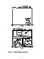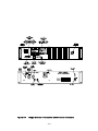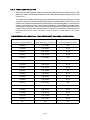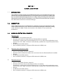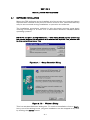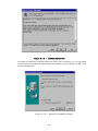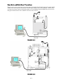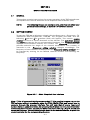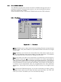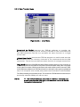
1
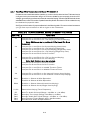
VHF/AM SINGLE CHANNEL
TRANSCEIVER
MODEL TiL-92-SC/8.33
(TSC-4100/4200/4300)
25 WATT TRANSCEIVER P/N 921018-1 (TSC-4100)
15 WATT TRANSCEIVER P/N 921018-2 (TSC-4200)
7 WATT TRANSCEIVER P/N 921018-3 (TSC-4300)
Installation and
Operating Instructions
Til Document No.
02RE305
Rev. N/C
November 2002
Technisonic Industries Limited
240 Traders Blvd., Mississauga, Ontario L4Z 1W7 Tel:(905)890-2113 Fax:(905)890-5338
web site: www.til.ca
WARNING
Do not make physical contact with antenna when transmitter is on. This unit can produce up to 30 watts of
power (depending on configuration) when transmitting.
CAUTION
This unit contains static sensitive devices. Wear a grounded wrist strap and/or conductive gloves when handling
printed circuit boards.
WARRANTY INFORMATION
The rack mounted Single Channel Transceiver, Model 92-SC series is under warranty for one year from date of
purchase. Failed units caused by defective parts, or workmanship should be returned to:
Technisonic Industries Limited
240 Traders Blvd.
Mississauga,
Ontario L4Z 1W7
Tel: (905) 890-2113
Fax: (905) 890-5338
Amherst, NY
Tel: (716) 691-0669
A Page
REVISIONS
REV
N/C
PAGE
DESCRIPTION
Original Release for TSC4100/4200/4300 units with
8.33kHz spacing capability.
DATE
APPROVED
Nov.
2002
R.R.
TABLE OF CONTENTS
Paragraph
SECTION 1
1.1
1.2
1.2.1
1.2.2
1.2.3
1.2.4
1.2.5
1.2.6
1.2.7
1.3
1.3.1
1.3.1.1
1.3.2
1.4
SECTION 2
2.1
2.2
2.2.1
2.2.2
2.2.3
2.2.4
2.2.5
2.3
2.3.1
2.3.2
2.4
2.4.1
2.4.2
2.5
2.6
2.7
Title
Page
GENERAL DESCRIPTION
Introduction . . . . . . . . . . . . . . . . . . . . . . . . . . . . . . .
Description . . . . . . . . . . . . . . . . . . . . . . . . . . . . . . .
Transceiver Module . . . . . . . . . . . . . . . . . . . . . . . . .
Power Supply Modules - P/N’s 922079-1,922083-1
RF Amplifier Modules - Models PA-15, PA-25 . . . . .
Mother Board - P/N 923056-2 . . . . . . . . . . . . . . . . .
Remote Control Boards . . . . . . . . . . . . . . . . . . . . . .
Crystal Filter (Option 1) . . . . . . . . . . . . . . . . . . . . . .
RF Isolator . . . . . . . . . . . . . . . . . . . . . . . . . . . . . . . .
Modes of Operation . . . . . . . . . . . . . . . . . . . . . . . . .
Local/Remote Operation . . . . . . . . . . . . . . . . . . . . . .
Conference audio . . . . . . . . . . . . . . . . . . . . . . . . . . .
AC and DC Operation . . . . . . . . . . . . . . . . . . . . . . . .
Technical Summary . . . . . . . . . . . . . . . . . . . . . . . . .
.
.
.
.
.
.
.
.
.
.
.
.
.
.
.
.
.
.
.
.
.
.
.
.
.
.
.
.
.
.
.
.
.
.
.
.
.
.
.
.
.
.
.
.
.
.
.
.
.
.
.
.
.
.
.
.
.
.
.
.
.
.
.
.
.
.
.
.
.
.
.
.
.
.
.
.
.
.
.
.
.
.
.
.
.
.
.
.
.
.
.
.
.
.
.
.
.
.
.
.
.
.
.
.
.
.
.
.
.
.
.
.
.
.
.
.
.
.
.
.
.
.
.
.
.
.
1-1
1-1
1-2
1-2
1-2
1-2
1-3
1-3
1-3
1-3
1-3
1-4
1-4
1-4
.
.
.
.
.
.
.
.
.
.
.
.
.
.
.
.
.
.
.
.
.
.
.
.
.
.
.
.
.
.
.
.
.
.
.
.
.
.
.
.
.
.
.
.
.
.
.
.
.
.
.
.
.
.
.
.
.
.
.
.
.
.
.
.
.
.
.
.
.
.
.
.
.
.
.
.
.
.
.
.
.
.
.
.
.
.
.
.
.
.
.
.
.
.
.
.
.
.
.
.
.
.
.
.
.
.
.
.
.
.
.
.
.
.
.
.
.
.
.
.
.
.
.
.
.
.
.
.
.
.
.
.
.
.
.
.
.
.
2-1
2-1
2-1
2-1
2-3
2-3
2-4
2-5
2-6
2-7
2-10
2-10
2-10
2-10
2-10
2-10
PREPARATION FOR USE AND STORAGE
Introduction . . . . . . . . . . . . . . . . . . . . . . . . . . . . .
Disassembly/Assembly . . . . . . . . . . . . . . . . . . . . .
Remove/Replace Cover Assembly . . . . . . . . . . . . .
Remove/Replace Transceiver Module . . . . . . . . . .
Remove/Replace Memory Set Board Module A5A1
Remove/Replace Control Board . . . . . . . . . . . . . .
Remove/Replace Crystal Filter Board, P/N 923069
Remote Operation Set Up . . . . . . . . . . . . . . . . . . .
Remote Control Board P/N 923051-1 . . . . . . . . . .
Remote Control Board P/N 943180-1 . . . . . . . . . .
Optional Loudspeaker, Headphone Installation . . .
External Loudspeaker . . . . . . . . . . . . . . . . . . . . . .
Headset . . . . . . . . . . . . . . . . . . . . . . . . . . . . . . . .
Transceiver Adjustments and Settings . . . . . . . .
Operational Check . . . . . . . . . . . . . . . . . . . . . . . .
Storage . . . . . . . . . . . . . . . . . . . . . . . . . . . . . . . .
i
.
.
.
.
.
.
.
.
.
.
.
.
.
.
.
.
.
.
.
.
.
.
.
.
.
.
.
.
.
.
.
.
TABLE OF CONTENTS (Continued)
Paragraph
Title
SECTION 3
INSTRUCTIONS
3.1
3.2
3.3
3.4
3.4.1
3.4.2
3.4.3
3.4.4
3.5
3.5.1
3.5.2
3.5.3
3.5.4
3.5.5
3.5.6
Page
OPERATING AND CHANNEL PROGRAMMING
Introduction . . . . . . . . . . . . . . . . . . . . . . . . .
Installation . . . . . . . . . . . . . . . . . . . . . . . . . .
Operator's Switches, Controls and Indicators
Operating Instructions . . . . . . . . . . . . . . . . .
Transmitter Operation (Local Mode) . . . . . . .
Receiver Operation (Local Mode) . . . . . . . . .
Switching OFF . . . . . . . . . . . . . . . . . . . . . . .
External DC Operation . . . . . . . . . . . . . . . . .
Channel Frequency Selection . . . . . . . . . . . .
Introduction . . . . . . . . . . . . . . . . . . . . . . . . .
Frequency Range . . . . . . . . . . . . . . . . . . . . .
Preparation . . . . . . . . . . . . . . . . . . . . . . . . .
Frequency Selection . . . . . . . . . . . . . . . . . . .
Preprogramming Channel Frequencies . . . . .
Re-Assembly . . . . . . . . . . . . . . . . . . . . . . . .
.
.
.
.
.
.
.
.
.
.
.
.
.
.
.
.
.
.
.
.
.
.
.
.
.
.
.
.
.
.
.
.
.
.
.
.
.
.
.
.
.
.
.
.
.
.
.
.
.
.
.
.
.
.
.
.
.
.
.
.
.
.
.
.
.
.
.
.
.
.
.
.
.
.
.
.
.
.
.
.
.
.
.
.
.
.
.
.
.
.
.
.
.
.
.
.
.
.
.
.
.
.
.
.
.
.
.
.
.
.
.
.
.
.
.
.
.
.
.
.
.
.
.
.
.
.
.
.
.
.
.
.
.
.
.
.
.
.
.
.
.
.
.
.
.
.
.
.
.
.
.
.
.
.
.
.
.
.
.
.
.
.
.
.
.
.
.
.
.
.
.
.
.
.
.
.
.
.
.
.
.
.
.
.
.
.
.
.
.
.
.
.
.
.
.
.
.
.
.
.
.
.
.
.
.
.
.
.
.
.
.
.
.
.
.
.
.
.
.
.
.
.
.
3-1
3-1
3-1
3-5
3-5
3-6
3-7
3-7
3-8
3-8
3-8
3-8
3-9
3-10
3-10
LIST OF TABLES
Table No.
1-1
1-2
2-1
2-2
2-3
3-1
Title
TSC-4100/4200/4300/8.33 Configurations . . .
92-SC/8.33 Leading Particulars . . . . . . . . . . .
Remote Control Connector Functions . . . . . . .
Remote Control Board P/N 923051-1 Settings
Remote Control Board P/N 943180-1 Settings
Operator's Switches, Controls and Indicators .
Page
.
.
.
.
.
.
.
.
.
.
.
.
.
.
.
.
.
.
.
.
.
.
.
.
.
.
.
.
.
.
.
.
.
.
.
.
.
.
.
.
.
.
.
.
.
.
.
.
.
.
.
.
.
.
.
.
.
.
.
.
.
.
.
.
.
.
.
.
.
.
.
.
.
.
.
.
.
.
.
.
.
.
.
.
.
.
.
.
.
.
.
.
.
.
.
.
.
.
.
.
.
.
1-1
1-5
2-5
2-6
2-7
3-3
LIST OF ILLUSTRATIONS
Figure No.
1-1
2-1
2-2
2-3
2-4
3-1
Title
VHF/AM Single Channel Transceiver . . . . . . . . . . .
Single Channel Transceiver - Internal View . . . . . . .
Remote Control Board P/N 923051-1 . . . . . . . . . . .
Remote Control Board P/N 943180-1 . . . . . . . . . . .
Transceiver Adjustments and Settings . . . . . . . . . .
Single Channel Transceiver Controls and Indicators
ii
Page
.
.
.
.
.
.
.
.
.
.
.
.
.
.
.
.
.
.
.
.
.
.
.
.
.
.
.
.
.
.
.
.
.
.
.
.
.
.
.
.
.
.
.
.
.
.
.
.
.
.
.
.
.
.
.
.
.
.
.
.
.
.
.
.
.
.
.
.
.
.
. 1-1
. 2-2
. 2-8
. 2-9
.2-11
. . 3-2
SECTION 1
GENERAL DESCRIPTION
1.1
INTRODUCTION
This publication provides general information on the VHF/AM Single Channel Transceivers, Model TiL92-SC/8.33, Part Nos. 921018-1/8.33, 921018-2/8.33, and 921018-3/8.33 manufactured by Technisonic
Industries Limited. The /8.33 suffix indicates that the Option 8.33 which will allow operation with
8.33kHz spacing in addition to 25kHz spacing. These units are also referred to by Item No.'s TSC4100/8.33, TSC-4200/8.33 and TSC-4300/8.33 respectively. This document covers the configuration
of this equipment that utilizes either of the following remote control cards; p/n’s 923051-1 (standard)
or 943180-1 (supplied upon request). These cards allow the transceiver to be remotely controlled over
600 ohm dedicated lines using a variety of keying methods.
The Model TiL-92-SC/8.33 Transceivers are simplex, single channel, fixed frequency transceivers
operating over the frequency range of 117.975 MHz to 138.000 MHz. These units are intended for base
station operation in an air traffic environment. These systems can operate from AC power or external
DC power in local and remote operating modes.
1.2
DESCRIPTION
The three rack mounted transceiver configurations are based on the Model 90-6R/8.33 preprogrammable transceiver configured for 7 Watt, 15 Watt or 25 Watt operation. All systems can be
configured for 2 Wire and 4 Wire remote operation with a variety of remote keying methods (with
923051-1 standard card). Each configuration consists of a Power Supply Module, Mother Board, and
a Remote Control Board. The 15 Watt and 25 Watt configurations also consist of an RF Amplifier
Module.
To improve the rejection of interfering signals, dual conversion receiver technology has been
incorporated on the Transmitter/Receiver (Module A1) board used in Technisonic VHF/AM base
stations. The second IF is 455kHz using a ceramic filter, which is immune to high energy ringing.
The dual conversion module also has a second local oscillator, second mixer and ceramic filter.
The first local oscillator is the original VCO.
The dual conversion receiver board, P/N 003494-1 is utilized in all TBS and TSC series base stations
with 8.33 spacing capability. An option label on the chassis will indicate OPTION 8.33 if the dual
conversion board with 8.33 kHz spacing capability is installed. Please note that all transceivers
capable of 8.33 and 25 kHz spacing will employ a dual conversion board.
The dual conversion receiver’s squelch knob must be rotated significantly more clockwise (4
o’clock position) to obtain the same squelch setting (3uV) as a single conversion (25kHz spacing
only) receiver’s squelch knob set to the 12 o’clock (straight up) position.
If the dual conversion receiver’s squelch knob is set to the 12 o’clock position, signals with a level
greater than 0.5uV will open the squelch. At most airports this will not be an adequate level of
squelch. Please be aware of this squelch knob adjustment variance when setting and/or
comparing squelch levels of dual conversion vs. single conversion base stations.
1-1
An optional RF Crystal Filter which provides higher receiver selectivity is available. These filters can be
ordered to provide either an additional 20dB (4 dB loss sensitivity) or 40dB (7 dB loss) of selectivity.
These filters can only be utilized in the 25 kHz spacing mode. An RF Isolator which provides
unidirectional coupling to the antenna in multiple transmitter configurations is now standard. Refer to
Table 1-1 for system configuration details.
TABLE 1-1
System
TSC-4100/4200/4300 CONFIGURATIONS
Motherboard
w/ 25 pin
connector
AC Power
supply
module
RF
Amplifier
Remote
Control
Cards
Not
required
P/N 9230511
or
P/N 9431801
(upon
request)
TSC-4300/8.33
923056-2
922079-1
TSC-4200/8.33
923056-2
922083-1
TSC-4100/8.33
923056-2
922083-1
Model PA15
Model PA25
1.2.1 Transceiver Module
The Single Channel Transceiver is based on Transceiver Model 90-6R/8.33. The transceiver module is
a low power VHF/AM transceiver which can transmit or receive on independent, pre-programmable
synthesized frequencies, with 25kHz or 8.33kHz channel spacing in the frequency range 117.975 MHz
to 138.000 MHz. The single channel memory set board, module A5A1 is mounted external to the 906R/8.33 transceiver module to facilitate ease of frequency programming. Refer to above paragraph for
details on the new dual conversion receiver/transmitter A1 module.
1.2.2 Power Supply Modules - P/N’s 922079-1, 922083-1
The Power Supply Modules provide the DC supply voltage to the transceiver and linear amplifier, and
houses a battery charger which can provide charging and trickle charging to external rechargeable
batteries. P/N 922079-1 is for use in the 7 Watt configurations, P/N 922083-1 is for use in the 15 Watt
configurations and the 25 Watt configurations.
1.2.3 RF Amplifier Modules - Models PA-15, PA-25
The RF Amplifier modules provide 15 Watt (Model PA-15) or 25 Watt (Model PA-25) power output. The
RF Amplifiers are fed by the 7 Watt RF output from the transceiver module. An internal mounted RF
Relay bypasses the RF Amplifier when in receive mode.
1.2.4 Mother Board, p/n 923056-2
Mother Board, p/n 923056-2 is supplied with the two available remote control cards and supports both
a 25 pin “D” and 9 pin Positronics remote connectors on the back of the transceiver chassis. A RJ11
style connector is also provided which supports only 2-wire audio signals. The Mother Board provides
all interconnection between the three external remote control connectors, RF Amplifier Module, Power
Supply, Remote Control Board, and Transceiver. The Remote Control Boards, RF Isolator and all internal
fuses are mounted on the Mother Board.
1-2
1.2.5 Remote Control Boards
1.
Line Interface Board P/N 923051-1
Provides remote control transceiver operation on 2 wire or 4 wire 600 ohm lines. This board can be
configured to key the transmitter using a 2175 Hz* continuous tone (see below), plus/minus DC
Voltages, ground keying and internal or external DC (15 mA) current loop keying. Transmit and Receive
audio is user selectable for two wires or four wires. *Crystals for tone frequencies other than 2175 Hz
may be obtained by special order (ie/2380 Hz).
2.
Line Interface Board P/N 943180-1
Provides remote control transceiver operation on 2 wire dedicated 600 ohm lines utilizing the EIA multitone keying format found in the Land Mobile Industry. A high level 2175 tone followed by a 1950 Hz
guard tone and then a low level 2175 Hz continuous tone is utilized to key the transceiver. The 9431801 board can also be jumper strapped for standard aeronautical 2175 Hz continuous tone operation. DC
(15mA) current loop and ground keying is also supported. However this board does not support 4 wire
operation.
NOTE
P/N 923051-1 is the default board supplied in all units. The EIA multi-tone board P/N 943180-1 must
be special ordered. To determine which remote card your 92-SC has installed the Configuration label
on the side of the rack mount chassis should be consulted.
1.2.6 Crystal Filter Board Assembly P/N 923069-1 (Option 1)
The Crystal Filter is a 25 KHz bandpass filter which provides additional selectivity during receive
operation. The filter provides 5 dB (MAX) attenuation of RF signals ± 7.5 KHz from the receive frequency
and 20 dB (MIN) attenuation of RF signals ± 50.0 KHz from the receive carrier frequency. Loss in
sensitivity is about 4 dB. A higher 40dB attenuation crystal filter can also be ordered. Loss in
sensitivity is about 7 dB. All crystal filters are cut to the required frequency and require 6-8 weeks lead
time. This item is interchangeable in the field. Refer to Paragraph 2.2.5 for replacement instructions.
This item can only be utilized in the 25 kHz spacing mode. An 8.33kHz bandpass filter is not available.
If no crystal filter option is ordered, jumper board assembly P/N 923074-1 is
installed.
1.2.7 RF Isolator
The RF Isolator is a broadband (118 MHz - 138 MHz) RF directional coupler. The RF Isolator provides
20 dB of isolation between the antenna and RF Amplifier while providing 0.7 dB (Max.) insertion loss.
The RF isolator is located on the motherboard and is now provided in all 92-SC
equipment.
1.3
MODES OF OPERATION
1.3.1 Local/Remote Operation
NOTE
Local operation is not disabled when operating in Remote mode and Remote
operation is not disabled when operating in Local mode. The two operating
modes operate in parallel.
1-3
1.
LOCAL OPERATION - In local operation, voice audio, and keying (PTT) functions are routed
from the microphone (not supplied) to the transceiver. Receive audio is routed to the internal
loudspeaker and phone jack located on the front panel.
2.
REMOTE OPERATION - In Remote operation, transmit audio, keying (PTT), and receive audio
functions are routed over land lines to the 600 ohm remote inputs. Internal jumpers can be set
for ±DC, ground, or tone transmitter keying, and to provide a DC squelch signal and RF Output
Power signal depending on the remote control board installed. Receive audio is routed to the
internal loudspeaker and is adjustable by the volume control. Transmit audio is also routed to
the internal loudspeaker at an internally adjustable preset level (see
conference audio).
1.3.1.1
Conference Audio (Optional)
NOTE: This feature is only provided upon special order. The component (R7) discussed below
is left unpopulated on standard configuration radios.
Conference Audio provides the operator with Tx voice on the transceiver speaker when the
transmitter is remotely keyed from another location. The audio level of the transmit audio is
internally adjustable from 0.0W to 0.5W of audio output. The adjustment is performed via
rotation of the potentiometer R7 (see Figure 2-5 for location), which is accessible from the top
of the transceiver after removing the top dust cover of the unit.
NOTE: The transmit audio level can be increased by rotating potentiometer R7clockwise and
decreased by counterclockwise rotation. If further adjustment of conference audio is required,
the top cover of the transceiver module must be removed to gain access to potentiometer R63,
located on the Audio Interface Module, A3 (see Figure 2-5 for location).
1.3.2 AC and DC Operation
The unit can be operated by external 120 VAC or external 28 VDC (13.7 VDC for 7W configurations).
The AC power supply can also be set to allow operation on 240 VAC.
1.4
1.
AC OPERATION - During AC operation, the unit can charge and trickle charge external batteries
via the external connectors mounted on the rear panel of the unit. Refer to section 3 for remote
connector pin details regarding DC operation.
2.
DC OPERATION - The unit can be operated from an external DC supply within the range of 21.6
Vdc to 30 Vdc for 15 watt and 25 watt configurations and within the range of 11.5 Vdc to 15.0
Vdc for 7 watt configurations.
TECHNICAL SUMMARY
A summary of electrical, operational, mechanical and physical characteristics of the Single Channel
Transceivers are provided in Table 1-2.
1-4
TABLE 1-2
92-SC LEADING PARTICULARS
POWER REQUIREMENTS:
7 Watt Transceiver
AC Input Voltage/Current
DC Input Voltage/Current
15 Watt Transceiver
AC Input Voltage/Current
DC Input Voltage/Current
25 Watt Transceiver
AC Input Voltage/Current
DC Input Voltage/Current
POWER OUTPUT:
7 Watt Transceiver . . . . . . . . . .
15 Watt Transceiver . . . . . . . . .
25 Watt Transceiver . . . . . . . . .
. . . . . . . . . . . 100 to 132 VAC @ 1.0 Amp
. . . . . . . . 11.5 VDC to 15 VDC @ 3.5 Amp
. . . . . . . . . . . 100 to 132 VAC @ 1.5 Amp
. . . . . . . . 21.6 VDC to 30 VDC @ 4.0 Amp
. . . . . . . . . . . 100 to 132 VAC @ 2.0 Amp
. . . . . . . . 21.6 VDC to 30 VDC @ 7.5 Amp
. . . . . . . . . . . . . . . . . . . . . . . . 5-10 Watts
. . . . . . . . . . . . . . . . . . . . . . . 10-20 Watts
. . . . . . . . . . . . . . . . . . . . . . . 20-30 Watts
Microphone Compression Range . . . . . . . . . . . . . . . . . . . . . . . . . . . . . . . . 35 dB
Battery Charger Voltage & Current . . . . . . . . . . . . . . . . 27.5 Vdc, 3.5 Amps MAX
REMOTE CONTROL BOARD, P/N 923051-1 specifications:
Remote Audio Input . . . . . . . . . . . . 2 or 4 wire (selectable), balanced 600 S lines
Remote Tx Timeout . . . . . . . . . . . . . . . . . . . . . . . . . . . . . . . . 30 to 300 seconds
Tone Keying:
Impedance . . . . . . . . . . . . . . . . . . . . . . . . . 600 S floating with respect to ground
Tx Control Tone . . . . . . . . . . . . . . . . . . . . . . . . . . . . . . . . . . . 2175 Hz, standard
Tx Tone Input Level . . . . . . . . . . . . . . . . . . . . . . . . . . . . . . . . . . . . 0 to -40 dBm
Tx Tone Control Response Time . . . . . . . . . . . . . . . . . . . . . . . . . <12 milliseconds
DC Keying . . . . . . . . . . . . . . . . . . . . . . . . . . . . . . . . . . . . . . . . . . . . . . . ±48 Vdc
Loop Resistance . . . . . . . . . . . . . . . . . . . . . . . . . . . . . . . . . . . . . . . . . 10 KS MAX
Ground Keying . . . . . . . . . . . . . . . . . . . . . . . . . . . . . . . . . . . . . Closure to Ground
Loop Resistance . . . . . . . . . . . . . . . . . . . . . . . . . . . . . . . . . . . . . . . . . . 4 KS MAX
Remote RX:
Range . . . . . . . . . . . . . . . . . . . . . . +10 dBm to -15 dBm (Factory set to -10dBm)
Impedance . . . . . . . . . . . . . . . . . . . . . . . . . 600 S floating with respect to ground
RX/TX Interface Signals:
Squelch Signal . . . . . . . . . . . . . . . . . . . . . . . . . . . . Ground, Open circuit for Mute
TX RF Output Signal . . . . . . . . . . . . . . . . . RF ON=Ground,RF OFF=Open Circuit
AGC Signal Output . . . . . . . . . . . . . . . . . . . . . . . . . . . . . . . . Linear 0 to +6 Vdc
Temperature & Humidity:
Operating Temperature Range . . . . . . . . . . -25EC(-13EF) to +55EC(+131EF)
Storage Temperature Range . . . . . . . . . . . -55EC(-67EF) to +65EC(+149EF)
Relative Humidity . . . . . . . . . . . . . . . . . . . . . . . . . . . . . . . . . . . . . . . 100%
Dimensions & Weight:
Width . . . . . . .
Height . . . . . . .
Depth . . . . . . .
Weight . . . . . . .
.
.
.
.
.
.
.
.
.
.
.
.
.
.
.
.
.
.
.
.
.
.
.
.
.
.
.
.
.
.
.
.
.
.
.
.
.
.
.
.
.
.
.
.
.
.
.
.
.
.
.
.
.
.
.
.
.
.
.
.
1-5
.
.
.
.
.
.
.
.
.
.
.
.
.
.
.
.
.
.
.
.
.
.
.
.
.
.
.
.
.
.
.
.
.
.
.
.
.
.
.
.
.
.
.
.
.
.
.
.
483 mm (19.0 in)
. . 89 mm (3.5 in)
432 mm (17.0 in)
. . 6.3 Kg (14 lbs)
MAX
MAX
MAX
MAX
TABLE 1-2
92-SC LEADING PARTICULARS (Continued)
TRANSCEIVER MODULE:
Dimensions & Weight:
Width . . . . . . . . . . . . . . . . . . . . . . . . . . . . . . . . . . . 216 mm (8.5 in) MAX
Height . . . . . . . . . . . . . . . . . . . . . . . . . . . . . . . . . . . 70 mm (2.75 in) MAX
Depth . . . . . . . . . . . . . . . . . . . . . . . . . . . . . . . . . 260 mm (10.25 in) MAX
Weight . . . . . . . . . . . . . . . . . . . . . . . . . . . . . . . . . 1.8 Kg (3 lb 15 oz) MAX
TRANSMITTER:
Power Output . . . . . . . . . . . . . . . . . . . . . . . . . . . . . . . . . . . . . 5-10 Watts
Audio Input . . . . . . . . . . . . . . . . . . . . . . . . . . . . . . 0.05 Vrms to 2.0 Vrms
Speech Processor Dynamic Range . . . . . . . . . . . . . . . . . . . . . . . . . . 35 dB
Modulation . . . . . . . . . . . . . . . . . . . . . . . . . . . . . . . . . . . . . . . . 95% MAX
Audio Distortion @ 90% mod (Low Power) . . . . . . . . . . . . . . . . . 10% MAX
Audio Distortion @ 90% mod (with Linear Amplifier at High Power)15% MAX
Audio Frequency Response . . . . . . . . . . . . 300 Hz to 2,500 Hz, +1, -3 dB
Spurious Emissions . . . . . . . . . . . . . . . . . . . . . . . . . . 60 dB below carrier
Hum and Noise . . . . . . . . . . . . . . . . . . . . . 45 dB below modulated carrier
RECEIVER:
RF Input Impedance . . . . . . . . . . . . . . . . . . . . . . . . . 50S, VSWR 2:1 MAX
Sensitivity (12 dB SINAD) @ 1 KHz 30% Mod . . . . . . . . . . . . . . . 1.5 µvolts
Selectivity, 25 KHz Channel Spacing:
6 dB Bandwidth . . . . . . . . . . . . . . . . . . . . . . . Greater than 14 KHz
80 dB Bandwidth . . . . . . . . . . . . . . . . . . . . . . . . Less Than 50 KHz
Selectivity, 8.33kHz Channel Spacing:
Bandwidth at 6dBpoints . . . . . . . . . . . . More than 10kHz((±5kHz)
Bandwidth at 60dB Points . . . . . . Less than than 15 KHz((±7.5kHz
Adjacent Channel Selectivity (for 25kHz and 8.33kHz) Greater Than 85 dB
Spurious Response Attenuation . . . . . . . . . . . . . . . . . . Greater than 95 dB
Frequency Stability (-40EC to +55EC) . . . . . . . . . . . . . . . . ±1,000 Hz MAX
RF AGC (5 µvolts to 1 volt) . . . . . . . . Audio Level change of less than 3 dB
Intermodulation:
Ultimate Sensitivity . . . . . . . . . . . . . . . . . . . . . . . . . . . . . . . . 70 dB
30 µvolts . . . . . . . . . . . . . . . . . . . . . . . . . . . . . . . . . . . . . . . . 45 dB
300 µvolts . . . . . . . . . . . . . . . . . . . . . . . . . . . . . . . . . . . . . . . 30 dB
Unwanted Radiation . . . . . . . . . . . . . . . . . . Less than 80 µvolts into 50 S
Hum & Noise @ 1mV RF 30% MOD . . . . . . . . . . . . . . . . . . . . . . . . . 40 dB
Loudspeaker Output . . . . . . . . . . . . . . . . . . . . . . . . . . . . 3 W MAX
Phone Output . . . . . . . . . . . . . . . . . . . . . . . . . 100 mW into 600 S
Audio Distortion 1mV RF Input, 30% MOD . . . . . . . . . . . . . 3% MAX
Audio Distortion 1mV RF Input, 90% MOD . . . . . . . . . . . . . . . . . . 5% MAX
Audio Output Limiting . . . . . . . . . . . . . Less than 1 dB @30 to 100% MOD
Audio Frequency Response 300 Hz-2500 Hz . . . . . . . . . . . . . . . . +1 -3 dB
Audio Acquisition Time . . . . . . . . . . . . . . . . . . . . . . . Less than 50 msecs
Audio Squelch Characteristics:
Squelch Type . . . . . . . . . . . . . . . . . . . . . Noise and Carrier Operated
Carrier and Noise Operated Squelch . . . . . . . . . . . Adjustable 2 to 15 µvolts
1-6
SECTION 2
PREPARATION FOR USE AND STORAGE
2.1
INTRODUCTION
This section provides the information required for custom configuration and storage of the Single
Channel Transceiver. Custom system configuration includes customizing remote control board
functions.
CAUTION: Antenna must be connected to transceiver before transmitting or permanent damage to
the output stage may occur.
2.2
DISASSEMBLY/ASSEMBLY (Refer to Figure 2-1)
2.2.1 Remove/Replace Top Dust Cover Assembly
REMOVAL
(1)
Remove and retain twelve screws securing top dust cover to the 19" rack chassis.
(2)
Please note the location of the three longer screws which travel through the heatsink shims
rivetted to the inside of the top cover.
(3)
Lift cover clear of chassis to expose internal view of transceiver as shown in
Figure 2-1.
REPLACEMENT
(1)
Position top cover on chassis.
(2)
Position one screw in each corner of the top cover mounting holes. Place the three longer
screws into their correct holes located over the internal transceiver module.
(3)
Secure cover to chassis with remaining screws.
2.2.2 Remove/Replace Transceiver Module
REMOVAL
(1)
Remove dust cover as described in paragraph 2.2.1.
(2)
Disconnect RF and DC connectors from rear of transceiver module.
(3)
Remove and retain the screws securing the top cover of the internal
transceiver module.
(4)
Remove and retain two screws and two washers securing flat cable to the side of the
transceiver module and disconnect the flat cable. Disconnect the flat cable running out of the
transceiver module at the connector on the external memory set board.
(5)
Remove and Retain four countersunk screws securing transceiver module
to front panel.
2-1
Figure 2-1
Single Channel Transceiver - Internal View
2-2
(6)
Move the transceiver module slightly back from the front panel and disconnect the flat cable
connecting the front panel assembly to the transceiver module, audio interface board A3. The
connector is located on the A3 board.
(7)
Lift transceiver module clear of chassis.
REPLACEMENT
(1)
Position the transceiver module into the chassis. While holding the transceiver module slightly
back from the front panel, re-connect the flat cable from the front panel to the A3 board in the
transceiver module.
(2)
Position and secure transceiver module to front panel with four
countersunk screws.
(3)
Re-connect flat cable to transceiver module. Secure flat cable to the side of transceiver module
with two screws and two washers. Connect flat cable running out of the transceiver module
to the external memory set board. Connect DC and RF connectors to rear of transceiver
module.
(4)
Replace and secure the top cover of the transceiver module with the screws removed in step
(3) of the REMOVAL instructions. Replace top dust cover as described in
paragraph 2.2.1.
2.2.3 Remove Replace External Single Channel Memory Set Module A5A1
REMOVAL
(1)
Remove dust cover as described in paragraph 2.2.1, remove top cover of transceiver module.
(2)
Disconnect the two crystal filter co-axial cable leads for jumper J2/P3 on the Rx/Tx module A1,
located in the transceiver module.
(3)
Remove and retain four screws securing Memory Set Board, Module A5A1 "piggy back" to the
standoffs on the power supply cover. (See Figure 2-1 for location).
REPLACEMENT
(1)
Secure the Memory Set Module to the stand-offs located on the power supply cover by the four
screws. Re-connect coaxial leads for RF crystal filter.
2.2.4 Remove/Replace Control Board
REMOVAL
(1)
Remove dust cover as described in paragraph 2.2.1.
CAUTION
(2)
Care must be taken when removing or replacing Control
Board to avoid damage to Motherboard Connector Pins.
Remove and retain four screws securing Control Board "piggy back" to the Mother Board
standoffs. Remove Control Board from Mother Board.
2-3
REPLACEMENT
(1)
Align the two female connectors on the control board with the male connectors on the Mother
Board using the four mounting holes and standoffs as a guide. Secure control board to the
Mother Board standoffs with four screws and washers.
(2)
Replace dust cover as described in paragraph 2.2.1.
2.2.5 Remove/Replace Crystal Filter Board, p/n 923069 or Jumper Board, p/n 923074
REMOVAL
(1)
Remove dust cover of unit as described in Paragraph 2.2.1.
(2)
Remove and retain the four screws securing the crystal filter board, p/n 923069-1 (or jumper
Board, p/n 923074) to the standoffs on the external frequency set module A5A1. Pull the crystal
filter board assembly straight up to avoid damaging the connector
pins.
REPLACEMENT
(1)
Align the pins on the bottom of the crystal filter board with their sockets on the memory set
board. Push the crystal filter board straight down until it rests on the memory set board
standoffs and secure with the four mounting screws.
(2)
Connect Module A5A1 co-axial jumper leads to jumper J2/P3 on Rx/Tx Module A1, if not
already connected. Either a crystal filter board, p/n 923074 or a jumper board, p/n 923074
must be installed and the A5A1 co-axial jumper leads connected to J2/P3 on the Rx/Tx Module
A1, for the receiver to work.
NOTE: Make certain that the memory set board, module A5A1 is programmed to the same operating
frequency as the crystal filter board assembly. If no crystal filter board assembly (option) is installed,
jumper board assembly P/N 923074-1 must be installed.
2-4
2.3
REMOTE OPERATION SETUP
The Procedures listed below enable the user to custom configure the unit for external remote control
hardware. Refer to Table 2-1 for connector pin details on Remote Control D Connector located at rear
of Single Channel Transceiver. Position Jumpers on Control board as indicated in Table 2-2 or Table 2-3
as required. Refer to Figure 2-2 and Figure 2-3 for board locations. Verify Remote Control operation in
accordance with manufacturers instructions.
TWO WIRE SETUP - In two wire operation, a single balanced 600 ohm pair is
provided for transmit and receive audio. The transmitter can be keyed on the
same pair or externally.
FOUR WIRE SETUP - In four wire operation, separate balanced 600 ohm pairs are provided for transmit
and receive audio. The transmitter can be keyed on the Tx audio pair or externally.
DC KEYING - In ± DC keying, a positive voltage between +10 Vdc and +48 Vdc or negative voltage
between -10 Vdc and -48 Vdc will key the transmitter. A DC voltage between -5 Vdc and +5 Vdc will
not key the transmitter.
TONE KEYING - In Tone keying a tone of 2175 Hz or 2380 Hz (Optional) can be used to key the
transmitter. Tone sensitivity is adjustable from -40 dBm to 0 dBm.
GROUND KEYING - In Ground Keying the transmitter is keyed by shorting the control point (landline or
External Keying) to chassis ground
CURRENT LOOP KEYING - In Current Loop keying, an internal or external current source (15 mA) is used
to key the transmitter
EIA TONE KEYING - The EIA multi-tone keying format is found in the Land Mobile Industry. A high level
2175 Hz tone followed by a 1950 Hz guard tone then a low level 2175 Hz continuous tone is utilized
to key the transceiver.
TABLE 2-1
REMOTE CONTROL CONNECTOR FUNCTIONS
9 PIN
NO
25 PIN
NO
Connector Pin Functions
A,B
C,D
H
N/A
K
J
N/A
E(-),F(+)
N/A
N/A
9,21
10,22
12,24
8
13
1,2,14,15
25
23(-),11(+)
20
3,4,5,6,7,16,17,
18, 19
4 Wire Tx Audio Line or 2 Wire Rx/Tx Audio Line (600 S)
4 Wire Rx Audio Line (600 S)
External DC In (+24 Vdc)
AGC
Single Line Keying (PTT)
Ground
Squelch
Carrier Control
RF Indicator
Not Connected, allocated for future functions
NOTE: A modular RJ-11 Jack is also provided on the rear of the 19" rack chassis for quick connection to the
2 wire, Tx/Rx Audio. The red and green wire connections (centre pins) on the RJ-11 are connected parallel to
pins 9 and 21 on the 25 pin connector. This RJ-11 jack CANNOT be used if the remote control card is set to 4wire operation as it does not have the necessary connections.
2-5
2.3.1 Two/Four Wire Remote Control Board P/N 923051-1
Provides remote control base station operation on 2 wire or 4 wire, 600 ohm lines. This board can be
configured to key the transmitter using a 2175 Hz tone (2380 Hz upon request), plus/minus DC
Voltages, ground keying and internal or external current loop keying. Transmit and Receive audio is user
selectable for two wires or four wires. Crystals for tone frequencies other than 2175 Hz or 2380 Hz may
be obtained by special order.
See Figure 2-2 for location of jumpers referred to in the following table. Pins are numbers increase as
you go from top to bottom or left to right on the connector.
TABLE 2-2
REMOTE CONTROL BOARD P/N 923051-1 SETTINGS
CONTROL
FUNCTION
J1
Jumper Pin 1 and Pin 2 for DC Current Loop Keying
Jumper Pin 2 and Pin 3 for ± DC Keying or Ground Keying.
Note: SW2 must be in position 2 if Pin 2 and Pin 3 are
jumpered.
J2
Jumper
Jumper
Jumper
Jumper
Jumper
J3
Jumper Pin 1 and Pin 2
Jumper Pin 4 and Pin 5
Note: Both Options
Jumper Pin 2 and Pin 3
Jumper Pin 5 and Pin 6
J7
Jumper Pin 1 and Pin 2 to enable Timeout Timer.
Jumper Pin 2 and Pin 3 to disable Timeout Timer.
J6
Jumper Pin 1 and Pin 2 to for Internal Current Loop Keying.
Jumper Pin 2 and Pin 3 to for External Current Loop Keying.
Pin
Pin
Pin
Pin
Pin
1
1
2
3
2
and
and
and
and
and
Pin
Pin
Pin
Pin
Pin
2
4
3
6
5
for
for
for
for
for
Ground Keying (Land Line).
± DC Keying (Land Line).
Ground Keying (Single Key Line).
± DC Keying (Single Key Line).
No Function.
for ± DC or Ground Keying.
for Tone Keying.
may be selected.
for No Function.
for No Function.
SW1
Position 1 Selects 2 Wire Operation.
Position 2 Selects 4 Wire Operation.
SW2
Position 1 Selects Normal (Land Line Keying).
Position 2 Selects Local (Single Line Keying).
Y1,Y2
Determines Keying Tone Frequency.
R7
R22
R25
R44
R10
Sets
Sets
Sets
Sets
Sets
Tx Audio IN Level (Range -18 dBm to +10 dBm).
Key Tone Level (Range -40 dBm to 0 dBm).
Rx Audio OUT Level (Range -15 dBm to +10 dBm).
Timeout Timer (Range 30 to 300 Seconds).
Receive Audio Output Balance.
2-6
2.3.2 Two Wire Line Interface Board P/N 943180-1
Provides remote control Base Station operation on 2 wire 600 ohm lines. Two wire Line Interface board
with EIA multi-tone, standard 2175Hz continuous tone, DC keying of ground keying over audio lines.
The multi-tone keying format consists of a high level 2175 tone followed by a 1950 Hz guard tone and
then a low level 2175 Hz continuous tone is utilized to key the transceiver. This board will also support
15mA current loop or ground keying. Refer to Figure 2-3 for jumper locations to set functions and line
level adjustments for this board. Summary of jumper settings follow. Pins are numbers increase as you
go from top to bottom or left to right on the connector.
Set J1 for ST (standard 2175Hz continuous) Tone keying or
for EIA (multi-tone keying format).
Set J2 for Tone keying function ON (left jumper position) or OFF (right jumper position).
Set J3 for Time out timer OFF (left jumper position) or ON (right jumper position).
See Figure 2-3 for location of jumpers and left/right orientation.
TABLE 2-3
REMOTE CONTROL BOARD P/N 943180-1 SETTINGS
CONTROL
FUNCTION
J1
Jumper Pin 1 and Pin 2 for ST (standard 2175 Hz continuous) tone Keying
Jumper Pin 2 and Pin 3 for EIA multi-tone Keying.
J2
Jumper Pin 1 and Pin 2 for Tone Keying.
Jumper Pin 4 and Pin 5 for Current Loop (15mA DC) or Ground Keying.
NOTE: Both options may be selected
Jumper Pin 2 and Pin 3 to disable Tone Keying.
Jumper Pin 5 and Pin 6 to disable Current Loop and Ground Keying.
J3
Jumper Pin 1 and Pin 2 to enable Timeout Timer.
Jumper Pin 2 and Pin 3 to disable Timeout Timer.
R6
R24
R26
R41
R59
R64
Tx audio level Adjustment
Keying Tone Attenuator
1950 Tone level Adjustment
2175 Tone Level Adjustment
Sets Rx Audio Level Adjustment (Range -15 dBm to +10 dBm).
Sets Timeout Timer (Range 30 to 300 Seconds)
2-7
Control Configuration for 2/4 Wire (+/-)DC/Ground/Tone/
(Current Loop) Keying Control Board.
Assembly #: 923051
R7:
R10:
R22:
R25:
R44:
SW1:
Tx Audio
(-25 dBm sensitivity;
increases clockwise).
2 Wire Rx Balance @ 600Ω
(1mV RF @ 1KHz, 30% Mod.)
R10 adjusted for minimum
amplitude at C6/R4 junction.
Keying Tone
(-30 dBm sensitivity;
decreases clockwise).
Rx Audio
(-10 dBm output level;
increases clockwise).
Time Out Timer
(15 to 300 sec.;
90 sec. Nominal;
increases clockwise).
Selects either 2 Wire
or 4 Wire operation.
SW2:
J1:
J2:
J3:
J6:
J7:
J4:
J5:
Selects either Local
or Land Line Current
Loop Keying.
Selects DC or Current
Loop Keying operation.
Selects either Land Line
(L/L) or Single Line (S/L)
and +/- DC or Ground
keying operation.
Selects Tone and/or +/- DC
Keying enable or disable.
Selects between Internal
or External Current loop
keying (ICL/ECL).
Keying timer
Enable/Disable.
Input Connector.
Output Connector.
NOTE: Bold Italics indicate Factory default configurations.
Figure 2-2
Line Interface/Remote Control Board P/N 923051-1
2-8
Control Configuration for Multi-Tone
Control Board.
Assembly #: 943180
R6:
R24:
R26:
R41:
R59:
R64:
Tx audio level adjustment (-25 dBm).
J1:
Standard or EIA
Keying Tone Attenuator.
Keying tone protocol.
1950 Hz tone level adjustment
J2:
Selects Tone and/or Current Loop/
2175 Hz tone level adjustment Ground Keying enable or disable
Rx Audio level adjustment.
J3:
Selects Keying timer Enable/Disable
(-10 dBm)
J4:
Input Connector
Time out timer
J5:
Output Connector
(90 sec. default)
NOTE: Bold Italics indicate Factory default configurations.
Figure 2-3
Line Interface/Remote Control Board P/N 943180-1
2-9
2.4
OPTIONAL LOUDSPEAKER, HEADPHONE INSTALLATION
Provision is made for connection of an external loudspeaker or headphone to the SPEAKER/PHONE jack
of the transceiver, as shown in Figure 3-1.
2.4.1 External Loudspeaker
When an external loudspeaker is to be installed, an 8-ohm nominal impedance loudspeaker should be
used. The loudspeaker cable should be terminated by a 1/4 in., 3-pole telephone plug (male), with the
loudspeaker connected between tip and sleeve (ground). Insert the external loudspeaker connector into
the SPEAKER/PHONE jack located on the front panel of the transceiver. When the external loudspeaker
is connected to the transceiver SPEAKER/PHONE jack, the internal loudspeaker is automatically
disconnected.
2.4.2 Headset
Headset impedance should be 150 to 600 ohms. The headset cable must terminate in a 1/4 in. 3-pole
telephone plug (male), to mate with the SPEAKER/PHONE jack located on the front panel of the
transceiver. The internal loudspeaker is automatically disconnected. Connect the headset as indicated
below for receiver audio with or without transmit audio.
2.5
(1)
HEADSET WITHOUT TRANSMIT AUDIO - When receiver audio only without transmit audio is
required, the headset should be connected between the tip and sleeve (ground) of the
telephone plug.
(2)
HEADSET WITH TRANSMIT AUDIO - When receiver audio with transmit audio is required, the
headset should be connected between the ring and sleeve (ground).
TRANSCEIVER ADJUSTMENTS AND SETTINGS
The locations at which certain transceiver settings and adjustments can be performed are shown in
Figure 2-4. The top dust cover of the transceiver must be removed as described in paragraph 2.2.1 to
access the AGC, Squelch and Modulation settings. The plastic plugs must be removed prior to
adjustment of the remaining settings which are accessed from the bottom of the transceiver chassis.
If alignment procedures for these settings are required please consult the manufacturer or the
appropriate service manual.
2.6
OPERATIONAL CHECK
Perform an operational check of the transceiver after all adjustments. Ensure that the transceiver
operates in both the transmit and receive modes of operation, using the Operating Instructions given
in Section 3 of this document and the appropriate specified operating procedures for use with the
Remote Control Unit.
2.7
STORAGE
To store for an extended period, store unit in a dry place, in the original shipping
container.
2-10
Figure 2-4
Transceiver Adjustments and Settings
2-11
SECTION 3
OPERATING INSTRUCTIONS
3.1
INTRODUCTION
This section includes a functional description of each switch, control, indicator and connector located
on the front and rear panels of the portable transceiver, including the PRESS-TO-TALK switch located
on the microphone. Operating instructions for transmit/receive and the special functions are also
included. Channel frequency and programming information is also included.
3.2
INSTALLATION
The Single Channel Transceivers are designed for mounting in a 19 inch rack. An AC Line cord P/N
927002-1 is supplied for connection to AC Power. A 9 Pin connector (mates with Positronic
GM9MSCG000VL or equivalent) and a 25 Pin Connector (mates with Amphenol 17D-B-25S or
equivalent) are provided for connection with external DC and 2 Wire or 4 Wire 600 ohm dedicated lines.
A 50 ohm "N" Type connector is provided for connection to an external antenna. Refer to Section 2 for
remote control setup details and section 3.5 for frequency selection and
programming.
3.3
(1)
Mount Transceiver in 19 inch rack with 4 screws.
(2)
Install Microphone in Microphone (PTT) connector if required.
(3)
Ensure that Transceiver POWER ON/OFF switch is set to OFF.
(4)
Install AC line cord in AC chassis connector on rear panel.
(5)
Install Remote Control connector to 9 Pin or 25 Pin connector as required. (Refer to Figure 3-1
for connector pin outs.)
(6)
Connect antenna connector to rear panel chassis N Type connector.
OPERATOR'S SWITCHES, CONTROLS AND INDICATORS
A view of the front and rear panel is given in Figure 3-1. A functional description of each of the
operator's switches, controls and indicators, and the microphone PRESS-TO-TALK switch, is given in
Table 3-1, Operator's Switches, Controls and Indicators.
3-1
Figure 3-1
Single Channel Transceiver Controls and Indicators
3-2
TABLE 3-1
Item
No.
OPERATOR'S SWITCHES, CONTROLS AND INDICATORS
SWITCHES
CONTROLS &
INDICATORS
FUNCTIONAL DESCRIPTION
1
POWER ON/OFF A toggle switch applies the AC power to the power supply and the DC
SWITCH
27.5 volts nominal power to the transceiver. The transceiver is switched
to ON in the toggle UP position the transceiver is switched OFF in the
toggle DOWN position.
2
POWER ON LED A GREEN LED Indicates when the POWER ON/OFF switch is set to ON and
INDICATOR
voltage is applied to the transceiver.
3
SQUELCH
CONTROL
A linear potentiometer determines the squelch threshold level. When the
SQUELCH CONTROL is rotated in the counter-clockwise direction, the
SQUELCH GREEN LED indicates that the squelch is connecting
demodulated audio to the VOLUME control.
4
SQUELCH
INDICATOR
A GREEN LED indicates the squelch circuit is connecting demodulated
audio signal to the VOLUME control.
5
Tx ON
AMBER LED
INDICATOR
An AMBER LED indicates when the transceiver is keyed by the microphone
PRESS-TO-TALK (PTT) switch or remote land line, and the transceiver is
operated in the Tx mode. The Tx ON AMBER LED switches OFF, when the
transceiver is operated in the receive mode.
6
VOLUME
CONTROL
A logarithmic potentiometer determines the audio level applied to the
internal speaker when the transceiver is operated in the receive mode.
When the SPEAKER/PHONE connector is in use the internal loudspeaker is
disconnected and the VOLUME CONTROL sets the audio level applied to
the external speaker or headphone.
7
MIC/PTT
CONNECTOR
A standard 0.2 inch 3-pole jack is provided to connect a microphone with
PTT to the transceiver front panel.
8
TX LABEL
Indicates the frequency programmed for transmit.
3-3
TABLE 3-1
Item
No.
9
OPERATOR'S SWITCHES, CONTROLS AND INDICATORS (Continued)
SWITCHES
CONTROLS &
INDICATORS
FUNCTIONAL DESCRIPTION
RX LABEL
Indicates the frequency programmed for receive.
10
LOUDSPEAKER
An 8-ohm internal speaker reproduces the receiver audio output. The audio
line is disconnected from the internal loudspeaker when the transceiver is
operated in Tx mode or when the SPEAKER/PHONE
connector is in use.
11
SPEAKER/
PHONE CONNECTOR
A 3-pole connector provides interconnection to either an external
loudspeaker or headphone. When in use, the internal speaker is
disconnected and the VOLUME control sets the audio level applied to the
external speaker or headphone.
12
AC FUSE
A 2.5 Amp fuse protects the Base Station power supply from power supply
internal short circuit or transceiver short circuit.
13
* "N" TYPE
RF
CONNECTOR
A 50 ohm coaxial connector provides connection to
external antenna.
14
*AC POWER
CONNECTOR
3 Prong AC Connector for use with AC Power Cord P/N
927002-1.
15
*9 PIN
REMOTE
CONTROL
CONNECTOR
9 Pin "D" type connector provides connections required for remote
operation. Refer to Table 2-3 for connector details.
16
*25 PIN
REMOTE
CONTROL
CONNECTOR
25 Pin "D" type connector provides connections required for remote
operation. Refer to Table 2-3 for connector details.
17
*RJ-11 REMOTE
CONNECTOR
RJ-11 type connector provides parallel connection to the 2-Wire Tx/Rx
audio from remote/line interface board. This connector supports 2 wire
operation only.
* Denotes items located on rear panel.
3-4
3.4
OPERATING INSTRUCTIONS
NOTE
Refer to appropriate Operating Instructions for
use with Remote Control Unit.
NOTE
The following operating procedures
intended specifically for Local Operation.
are
(1)
Ensure that the microphone connector is connected to the MIC/PTT connector of the
transceiver.
(2)
Set the SQUELCH control in the fully counter-clockwise (CCW) position.
(3)
Set the VOLUME control in the 12 o'clock centre position.
(4)
Set the POWER ON/OFF switch to "ON".
(5)
Verify that the FUSE BLOWN red LED is OFF.
(6)
Verify that the POWER ON green LED is ON.
(7)
Proceed to operate in the transmit mode, paragraph 3.4.1 or operate in the receive
mode, paragraph 3.4.2 as required.
3.4.1 Transmitter Operation (Local Mode)
To operate the transceiver in the transmit mode, proceed as follows:
(1)
Set RF POWER switch (if applicable) to desired operating level.
(2)
Hold the microphone in one hand, with the upper edge of the microphone as close as
possible to the upper lip.
NOTE
This technique activates the noise cancelling
feature of the microphone. The microphone is
most effective when sound is ½ inch (12.7
mm) or more away from the microphone.
(3)
Press and hold the PRESS-TO-TALK switch of the microphone during
transmission.
(4)
Ensure that the Tx ON amber LED is ON.
(5)
Speak slowly and distinctly into the microphone using specified operating procedures
during transmission.
(6)
When message is ended, release the PRESS-TO-TALK switch of the
microphone.
3-5
(7)
The transceiver is now operating in the receive mode.
(8)
Verify that the Tx ON amber LED is OFF.
3.4.2 Receiver Operation (Local Mode)
To operate the transceiver in the receive mode, proceed as follows:
(1)
Ensure that the PRESS-TO-TALK switch on the microphone is NOT depressed, and
verify that the Tx ON amber LED is OFF.
(2)
Verify that the correct operating frequency is indicated on the front panel. Refer to Section 4
for Channel/Frequency selection.
(3)
Adjust the SQUELCH control to suit local reception conditions. When the SQUELCH
control is rotated in the counter-clockwise direction, the SQUELCH indicator green LED
will switch to ON, indicating that the squelch circuit is connecting the demodulated
audio output to the VOLUME control.
Further adjustment of the SQUELCH control determines the squelch
setting.
IMPORTANT NOTE
The dual conversion receiver’s squelch knob must be rotated significantly more
clockwise (4 o’clock position) to obtain the same squelch setting (3uV) as a single
conversion receiver’s squelch knob set to the 12 o’clock (straight up)
position.
If the dual conversion receiver’s squelch knob is set to the 12 o’clock position, signals
with a level greater than 0.5uV will open the squelch. At most airports this will not be
an adequate level of squelch.
Recommended procedure:
The squelch taper on a dual conversion receiver looks as follows:
Squelch knob position
12 o’clock
3 o’clock
3:30 position
4 o’clock
Fully clockwise
Squelch setting
0.5uV
1.2uV
2.5uV
3uV
9uV
It is recommended that the squelch be set to at least 2.5uV (3:30 knob position) at busy
airport locations. If ACARS signals are present on adjacent or nearby channels the
squelch level should be at least 3uV (4 o’clock) to prevent ACARS bleed
through.
3-6
(4)
The VOLUME control can then be adjusted in a clockwise direction to increase the audio level,
or in a counter-clockwise direction to decrease the audio level which can be heard on the
internal loudspeaker.
NOTE
When an external loudspeaker or headset is
connected to the SPEAKER/PHONE jack of the
transceiver, the internal loudspeaker is
automatically disconnected. The VOLUME
control will now control the audio level
applied to the external loudspeaker or headset,
as applicable.
3.4.3 Switching OFF
To switch off the transceiver:
(1)
Set the POWER ON/OFF on transceiver to switch to OFF.
(2)
Verify that all indicator LED's on the front panel are OFF.
NOTE
When the transceiver is switched OFF there is
no current drain from external DC.
3.4.4 EXTERNAL DC OPERATION
(1)
Set AC ON/OFF switch to OFF.
(2)
Refer to Table 2-3 for pin numbers and Figure 3-1 for pin locations to hook up external DC
Power.
NOTE
Ensure that the DC source voltage does not
exceed 30 Vdc. The 15 watt and 25 watt units
can operate within the range 21.6 Vdc to 30
Vdc. The 7 watt units can operate within the
range of 11.5 Vdc to 15.0 Vdc.
3-7
3.5
CHANNEL FREQUENCY SELECTION AND PROGRAMMING
3.5.1 INTRODUCTION
Transceiver Model 90-6R/8.33, Part Number 861605-2 Option 8.33, as shipped from the factory, is
preprogrammed with test frequencies. Before programming any other frequencies, perform an
operational check on Channel 1, as outlined in paragraph 2.6. If there is any operational deficiency or
equipment malfunction, the transceiver is to be returned to the manufacturer, Technisonic Industries
Limited, under warranty. Before installation, it is necessary to pre-program the desired operating
frequency for transmit and receive to be used at the particular airport.
3.5.2 FREQUENCY RANGE
The transceiver may be programmed for up to six frequencies over the frequency range 117.9750MHz
to 138.000MHz with 8.33kHz or 25kHz channel spacing.
3.5.3 PREPARATION
A personal computer is required to program frequencies into the transceiver
channel memories. Refer to document 01RE291 (Section 3, Addendum A) for detailed
instructions on TDP-90 software installation and operation.
A programming cable, TiL Part No. 013508-1, must be temporarily connected from header jack
J4 inside the radio to the computer serial port. To gain access to J4, perform the
following:
(1)
Place the transceiver on a bench with the top cover of the transceiver located on the bench
and the bottom cover exposed.
(2)
Remove and retain twelve Philips Pan Hd Screws 4-40 X 1/4in. lg and No.4 Lockwashers
securing the bottom cover to the main chassis of the transceiver.
(3)
Remove and retain the bottom cover.
(4)
Locate J4 on the Programmable Frequency Set Board.
(5)
Connect the 10 pin (female) block connector of the supplied Data Cable
(TiL Part No. 013508-1) to J4. Plug the 9 pin (female) D connector end
of the cable to an available Serial (COM) Port on your PC. A 9 pin serial
extension cable may be required if the transceiver is more than a few feet
away from the computer.
3-8
3.5.4 FREQUENCY SELECTION
Determine the specific frequency of each channel for the particular transceiver being worked on. See
Addendum A at the end of this document for use of the TDP-90 data programming software for this
transceiver.
The transceiver is capable of 25 kHz spacing (wide band) and 8.33 kHz spacing (narrow band)
channels. The frequency entered will determine whether the channel will be wide or narrow mode,
based on the Combined 8.33 kHz/25 kHz ICAO Frequency-Channel Pairing Plan. For example if you
program 118.000 into a memory, the transceiver will operate on 118.000 MHz in wide band mode.
If you program 118.005 into a memory, the transceiver will operate on 118.000 MHz in narrow band
mode. For the most part, this will be transparent to the user since a frequency will be issued in the
ICAO format and the radio will select wide or narrow mode. Refer to the chart
below.
TABLE 3-2
COMBINED 8.33/25 kHz ICAO FREQUENCY CHANNEL PAIRING PLAN
Frequency Entered (MHz)
Actual Operating Frequency
Channel Spacing (kHz)
118.000
118.0000
25
118.005
118.0000
8.33
118.010
118.0083
8.33
118.015
118.0166
8.33
118.025
118.0250
25
118.030
118.0250
8.33
118.035
118.0333
8.33
118.040
118.0416
8.33
118.050
118.0500
25
118.055
118.0500
8.33
118.060
118.0583
8.33
118.065
118.0666
8.33
118.075
118.0750
25
118.080
118.0750
8.33
118.085
118.0833
8.33
118.090
118.0916
8.33
118.100
118.1000
25
118.105
118.1000
8.33
etc
etc
etc
3-9
3.5.5 PROGRAMMING CHANNEL FREQUENCIES
Having ascertained the desired operating frequencies for each channel, continue
as follows:
(1)
Run the TDP-90 program on the computer.
(2)
Click on the Data pull-down list and select the serial port to which the
transceiver is connected.
(3)
Set the program for 1 or 6 channels as applicable.
(4)
Turn on power to the transceiver.
(5)
Click on the Up icon to retrieve the frequencies from the radio. You will
see activity in the Terminal window as data is being transferred.
(6)
Edit the frequencies as desired.
(7)
Click on the Dn icon to copy the frequencies to the transceiver. You will
see activity in the Terminal window as data is being transferred.
(8)
Click on the diskette icon to save the file.
(9)
Click on the printer icon to print a hard-copy of the frequencies.
(10)
Turn off power to the transceiver.
3.5.6
RE-ASSEMBLY
After frequency programming has been completed, remove the programming cable from J4 and
reassemble the transceiver as follows:
(1)
Disconnect the power cable to the transceiver.
(2)
Install the bottom cover on the main chassis of the transceiver utilizing screws and lock
washers retained during disassembly. Tighten Screws.
(3)
On the front panel label of the transceiver, mark the channel designation label with the
appropriate frequency against each channel preprogrammed.
Section 3
Addendum A
Til Document No.
02RE305
This document contains designs and other information which are the property of
Technisonic Industries Ltd. Except for rights expressly granted by contract to the
Canadian Government, or to the United States Government, this document may not
in whole or in part, be duplicated or disclosed or used for manufacture of the part
disclosed herein, without the prior permission of Technisonic Industries Ltd.
TiL TDP-90
Data Programming
Software
for 8.33 AM Series
Transceivers
Installation and
Operating Instructions
TiL Document No.
01RE291
Rev. n/c
August 2001
Technisonic Industries Limited
240 Traders Blvd. E., Mississauga, Ontario L4Z 1W7 Tel:(905)890-2113 Fax:(905)890-5338
www.til.ca
TABLE OF CONTENTS
Paragraph
SECTION 1
1.1
1.2
1.3
2.2
3.4
3.5
GENERAL DESCRIPTION
INSTALLATION INSTRUCTIONS
Software Installation . . . . . . . . . . . . .
2.1.1 - Windows 95 . . . . . . . . . . . . .
2.1.2 - Windows 98 / Windows 2000
2.1.3 - Windows NT 4.0 . . . . . . . . . .
Hardware Installation . . . . . . . . . . . .
SECTION 3
3.1
3.2
3.3
Page
Introduction . . . . . . . . . . . . . . . . . . . . . . . . . . . . . . . . . . . . . . . . . . . 1-1
Description . . . . . . . . . . . . . . . . . . . . . . . . . . . . . . . . . . . . . . . . . . . . 1-1
Minimum System Requirements . . . . . . . . . . . . . . . . . . . . . . . . . . . . 1-1
SECTION 2
2.1
Title
.
.
.
.
.
.
.
.
.
.
.
.
.
.
.
.
.
.
.
.
.
.
.
.
.
.
.
.
.
.
.
.
.
.
.
.
.
.
.
.
.
.
.
.
.
.
.
.
.
.
.
.
.
.
.
.
.
.
.
.
.
.
.
.
.
.
.
.
.
.
.
.
.
.
.
.
.
.
.
.
.
.
.
.
.
.
.
.
.
.
.
.
.
.
.
.
.
.
.
.
.
.
.
.
.
.
.
.
.
.
.
.
.
.
.
.
.
.
.
.
2-1
2-3
2-4
2-4
2-5
.
.
.
.
.
.
.
.
.
.
.
.
.
.
.
.
.
.
.
.
.
.
.
.
.
.
.
.
.
.
.
.
.
.
.
.
.
.
.
.
.
.
.
.
.
.
.
.
.
.
.
.
.
.
.
.
.
.
.
.
.
.
.
.
.
.
.
.
.
.
.
.
.
.
.
.
.
.
.
.
.
.
.
.
.
.
.
.
.
.
.
.
.
.
.
.
.
.
.
.
.
.
.
.
.
.
.
.
.
.
.
.
.
.
.
.
.
.
.
.
.
.
.
.
.
.
.
.
.
.
.
.
.
.
.
.
.
.
.
.
.
.
.
.
.
.
.
.
.
.
.
.
.
.
.
.
.
.
.
.
.
.
.
.
.
.
.
.
.
.
.
.
.
.
.
.
.
.
.
.
.
.
.
.
.
.
.
.
.
.
.
.
.
.
.
.
.
.
.
.
.
.
.
.
.
.
.
.
.
.
.
.
.
.
.
.
3-1
3-1
3-2
3-2
3-3
3-4
3-5
3-6
3-7
OPERATING INSTRUCTIONS
General . . . . . . . . . . . . . . . . . .
Getting Started . . . . . . . . . . . .
Pull Down Menus . . . . . . . . . .
3.3.1 - File Menu . . . . . . . . . .
3.3.2 - Data Transfer Menu . . .
3.3.3 - Help Menu . . . . . . . . .
3.3.4 - Channel Selection . . . .
Sample Upload and Download
RS-232 Serial Technical Data .
.
.
.
.
.
.
.
.
.
ii
.
.
.
.
.
.
.
.
.
.
.
.
.
.
.
.
.
.
.
.
.
.
.
.
.
.
.
.
.
.
.
.
.
.
.
.
LIST OF ILLUSTRATIONS
Figure No.
Title
2.1.1
2.1.2
2.1.3
2.1.4
Setup Extraction Dialog . . .
Welcome Dialog . . . . . . . .
License Agreement . . . . . .
Program Installation Dialog
2.2.1
2.2.2
2.2.3
Programming Connections for Mobile transceivers . . . . . . . . . . . . . . 2-6
Programming Connections for Base Station transceivers . . . . . . . . . . 2-7
Programming Connections for Rack Mount transceivers . . . . . . . . . . 2-7
3.3.1
3.3.2
3.3.3
3.3.4.1
3.3.4.2
File Menu Pull down . . .
Data Menu Pull down . .
Help Menu Pull down . .
Single Channel Selection
Six Channel Selection . . .
.
.
.
.
.
.
.
.
.
.
.
.
.
.
.
.
.
.
.
.
.
.
.
.
.
.
.
.
.
.
.
.
.
.
.
.
.
.
.
.
.
iii
.
.
.
.
.
.
.
.
.
.
.
.
.
.
.
.
.
.
.
.
.
.
.
.
.
.
.
.
.
.
.
.
.
.
.
.
.
.
.
.
.
.
.
.
.
.
.
.
.
Page
.
.
.
.
.
.
.
.
.
.
.
.
.
.
.
.
.
.
.
.
.
.
.
.
.
.
.
.
.
.
.
.
.
.
.
.
.
.
.
.
.
.
.
.
.
.
.
.
.
.
.
.
.
.
.
.
.
.
.
.
.
.
.
.
.
.
.
.
.
.
.
.
.
.
.
.
.
.
.
.
.
.
.
.
.
.
.
.
.
.
.
.
.
.
.
.
.
.
.
.
.
.
.
.
.
.
.
.
.
.
.
.
.
.
.
.
.
.
.
.
.
.
.
.
.
.
.
.
.
.
.
.
.
.
.
.
.
.
.
.
.
.
.
.
.
.
.
.
.
.
.
.
.
.
.
.
.
.
.
.
.
.
.
.
.
.
.
.
.
.
.
.
.
.
.
.
.
.
.
.
.
.
.
.
.
.
.
.
.
.
.
.
.
.
.
.
.
.
.
.
.
.
.
2-1
2-1
2-2
2-2
3-2
3-3
3-4
3-4
3-5
Copyright and Trademark acknowledgment
-
Microsoft, Windows 95, Windows 98, Windows NT, Windows 2000, DCOM, and Internet
Explorer are registered trademarks of Microsoft Corporation.
-
DPL is a registered trademark of Motorola Inc.
Adobe, Adobe Acrobat, and Adobe Acrobat Reader are registered trademark of Adobe Systems
Inc.
iv
SECTION 1
GENERAL DESCRIPTION
1.1
INTRODUCTION
This publication provides operating and installation information on the TiL TDP-90 Programming
Software for 8.33 kHz AM series transceivers. The TDP software allows a standard PC to retrieve data
from a connected 8.33kHz AM series transceiver, for editing, storing, and sharing with other 8.33 kHz
AM series transceivers. With the TDP software, you can create, save and print archives of your 8.33
kHz AM series transceiver channel settings.
1.2
DESCRIPTION
The TiL TDP-90 software is a 32 bit Windows application that will work under Windows 95,
Windows 98 and Windows NT 4.0. There are no known issues preventing the TDP-90 from working
under Windows 2000. Please see section 2 for details on your particular
installation.
1.3
MINIMUM SYSTEM REQUIREMENTS
Windows 95
•
•
•
•
•
or
Windows 98 / Windows 2000
•
•
•
•
•
or
Intel 486 or compatible based PC
Windows 95 with the latest Service Releases/Packs installed
(Installation of Microsoft Internet Explorer 5.0 or any Microsoft application more
recent than mid 1998, will have automatically updated the required system files.)
Mouse
5 MB free Hard-Disk space
One available properly configured RS-232 serial (COM) port
Intel or compatible Pentium class PC
Windows 98 or Windows 2000 with the latest Service Releases/Packs installed
Mouse
5 MB free Hard-Disk space
One available properly configured RS-232 serial (COM) port
Windows NT 4.0
•
•
•
•
•
Intel or compatible Pentium class PC
Windows NT 4.0 with at least Service Pack 4 installed
(Installation of Microsoft Internet Explorer 5.0 or any Microsoft application more
recent than mid 1998, will have automatically updated the required system files.)
Mouse
5 MB free Hard-Disk space
One available properly configured RS-232 serial (COM) port
1-1
SECTION 2
INSTALLATION INSTRUCTIONS
2.1
SOFTWARE INSTALLATION
Before the TDP software can be installed, all of the minimum computer system
requirements outlined in the previous section must be met, otherwise difficulty
may be encountered during installation or operation the software.
The installation procedures outlined in this document assume some basic
working knowledge of at least one of Microsoft's Windows 95/98/NT/2000
operating systems.
NOTE: At any point during installation, if any Dialog Boxes pop up exclaiming
that newer system files are about to be overwritten by older files, click on NO
to skip overwriting newer files.
Figure 2.1.1 - Setup Extraction Dialog
Figure 2.1.2 - Welcome Dialog
This is a standard Welcome dialog box. To continue installation click on Next>.
In any one of the dialog boxes, program installation can be stopped at any time
by clicking the Cancel button
2-1
Figure 2.1.3 - License Agreement
In order to Install the TDP-90 Software onto your computer, you must agree
to the terms of the license agreement, and confirm so by clicking on OK in the
License dialog box.
Figure 2.1.4 - Program Installation Dialog
2-2
2.1.1
Windows 95
If your computer does not have Microsoft Internet Explorer 5.0 or any other Microsoft
application, no later than mid 1998 installed, then it is possible that certain essential system
files are outdated. If these system files are outdated your system will not meet the minimum
requirements for installing and operating a large variety of new software including the TDP
software.
If your computer DOES meet the minimum requirements, you may
proceed to step 3.
1.
To update Windows 95, you will need to install an update available on Microsoft's website,
called DCOM95 (dcom95.exe). To download DCOM95, just enter this current (as of the
release date of this manual) Internet URL for the file in your ‘location bar’ in
your Internet Browser.
http://download.microsoft.com/msdownload/dcom/95/x86/en/dcom95
.exe
Your Browser will invoke a SAVE AS dialog box for you to save the file.
Keep track of where you place it, as you will be required to locate it and
RUN it. Conveniently, the file will fit on a regular IBM Formatted 3½"
1.44MB floppy disk, for easy transport and distribution.
If you have the DCOM95.EXE update file on a floppy disk, copy/place it
in a temporary location on your Hard-disk.
2.
RUN DCOM95 by locating and double-clicking on it in Windows
Explorer. Any System files on your computer that are OLDER than the
ones contained in the DCOM95 update, will be replaced. You will be
asked to restart your computer. Do so, and when the computer has
finished booting, you will have an updated Operating System that will
meet the requirements of the TDP software.
3.
To install the TDP software, locate the TDP90_Install.exe file on the
CD-ROM using Windows Explorer. When you have located it,
double-click it to start the setup process.
You will see the first Setup dialog (Figure 2.1.1). Click on the Setup
button to continue installation. The Setup will unpack the necessary
components. After it completes, you will see a Welcome dialog box.
Click Next> to continue. Before you can continue, you will have to agree
to the terms of the License Agreement by clicking OK (Figure 2.1.3).
The setup wizard may or may not ask to reboot the computer,
depending on which components your system required from the
installation package. If so, let the computer restart and run setup again
to complete the installation process. No further reboots will be required.
4.
After setup finishes unpacking the software, a dialog box will pop up
with the option to continue (by clicking on the Next> button see Figure
2.1.4), exit the setup, or at this time you may choose an alternate
location for the installation. If you have no objections to the default
location just click on the Next> button to continue the installation.
5.
The TDP installation will ask what START menu Program Group you
want the TDP software shortcut installed. Click FINISH if the default
Program Group name is adequate.
The Data Programming Software is now installed and ready to use with
an 8.3 kHz AM series Transceiver.
2-3
2.1.2 Windows 98 / Windows 2000
Windows 98 comes pre installed with Internet Explorer 5.0 embedded
into the operating system. As a result, the operating system as a whole
meets the requirements for the installation and operation of the TDP
software.
1.
To install the TDP software, locate the TDP90_Install.exe file on the
CD-ROM using Windows Explorer. When you have located it,
double-click it to start the setup process.
You will see the first Setup dialog (Figure 2.1.1). Click on the Setup
button to continue installation. The Setup will unpack the necessary
components. After it completes, you will see a Welcome dialog box.
Click Next> to continue. Before you can continue, you will have to agree
to the terms of the License Agreement by clicking OK (Figure 2.1.3).
The setup wizard may or may not ask to reboot the computer,
depending on which components your system required from the
installation package. If so, let the computer restart and run setup again
to complete the installation process. No further reboots will be required.
2.
After setup finishes unpacking the software, a dialog box will pop up
with the option to continue (by clicking on the Next> button see Figure
2.1.4), exit the setup, or at this time you may choose an alternate
location for the installation. If you have no objections to the default
location just click on the Next> button to continue the installation.
3.
The TDP installation will ask what START menu Program Group you
want the TDP software shortcut installed. Click FINISH if the default
Program Group name is adequate.
The Data Programming Software is now installed and ready to use with
an 8.33 kHz AM series Transceiver.
2.1.3 Windows NT 4.0
For a Windows NT 4.0 installation, a minimum of Service Pack 4 must
be installed. If you do not have at least Service Pack 4, contact Microsoft
for the most current Service Pack.
1.
To install the TDP software, locate the TDP90_Install.exe file on the
CD-ROM using Windows Explorer. When you have located it,
double-click it to start the setup process.
You will see the first Setup dialog (Figure 2.1.1). Click on the Setup
button to continue installation. The Setup will unpack the necessary
components. After it completes, you will see a Welcome dialog box.
Click Next> to continue. Before you can continue, you will have to agree
to the terms of the License Agreement by clicking OK (Figure 2.1.3).
The setup wizard may or may not ask to reboot the computer,
depending on which components your system required from the
installation package. If so, let the computer restart and run setup again
to complete the installation process. No further reboots will be required.
2-4
2.
After setup finishes unpacking the software, a dialog box will pop up
with the option to continue (by clicking on the Next> button see Figure
2.1.4), exit the setup, or at this time you may choose an alternate
location for the installation. If you have no objections to the default
location just click on the Next> button to continue the installation.
3.
The TDP installation will ask what START menu Program Group you
want the TDP software shortcut installed. Click FINISH if the default
Program Group name is adequate.
The Data Programming Software is now installed and ready to use with
an 8.33 kHz AM series Transceiver.
2-5
2.2
HARDWARE INSTALLATION
Mobile transceivers:
Remove the bottom cover from the transceiver chassis and locate J4 on the
Programmable Frequency Set Board. Connect the 10 pin (female) block connector of
the supplied Data Cable (TiL Part No. 013508-1) to J4. Plug the 9 pin (female) D
connector end of the cable to an available Serial (COM) Port on your PC. A 9 pin
serial extension cable may be required if the transceiver is more than two feet away
from the computer. Apply +13.8 VDC, (minimum 1 Amp) to the mobile transceiver
and turn the unit on.
FIGURE 2.2.1
2-6
Base Station and Rack Mount Transceivers:
Remove the top cover from the transceiver and plug the female end of a 9 pin serial
cable into the 9 pin D connector on the right side of the unit marked “Serial port”.
Connect the other end of the serial cable to an available Serial (COM) Port on your PC.
Plug the transceiver into 120VAC and turn the unit on.
FIGURE 2.2.2
FIGURE 2.2.3
2-7
SECTION 3
OPERATING INSTRUCTIONS
3.1
GENERAL
This section contains instructions for proper operation of the TDP-90 software
and explains the various elements of the Graphical User Interface (GUI).
NOTE:
3.2
The following images are examples only, and may not reflect your
particular data settings, or current TDP software version.
GETTING STARTED
To start the TDP-90 in Windows, simply click the Start menu > Programs > TiL
Transceiver Data Programmer >TDP-90. The program will start, and the
following Graphical User Interface (GUI) will appear. The current version
number is shown in square brackets on the title bar. The pull-down menus
and icons provide the set-up and operating functions. The Terminal window
displays communication activity as it occurs. The Channels pull-down tab
provides selection for single or six channel transceivers. The number of
channels in the
Frequency editing window changes accordingly. The
frequency of each channel, as displayed in the Frequency editing window, can
be changed by clicking on the desired channel window and entering the
frequency.
Figure 3.3.1 - Main Graphical User Interface
Note: ** Use of a mouse is highly recommended! ** It is possible however, to use the
TDP software without a mouse by using the [Tab], [Shift]+[Tab] and 'cursor' keys to
navigate through the program interface. You will note that all menu items and
buttons have an underlined letter. By pressing the [Alt] key and the underlined letter
in the menu bar or button, you can pull down that menu item. eg: [Alt]+F, would pull
down the file menu. You could then cursor down to the desired function, or press the
underlined letter for the corresponding function.
3-1
3.3
PULL DOWN MENUS
The TDP-90 program has several functions available through the use of
pull-down menus. Through these menus, you can invoke file functions,
print the channel list, initiate
communications with a connected TFM-90 and quit the TDP software.
3.3.1 File Menu
Figure 3.3.1 - File Menu
Open will allow you to select and load and existing file that was previously
saved on disk. The yellow folder icon provides the same function in a single
mouse click.
Save will allow you to save the current data into a file with a name of your
choice. The filename may be any length up to 64 characters. The diskette
icon provides the same function in a single mouse click.
Print will create a text file of the channel list, as presented in the Frequency
List window. Once the Print function is invoked, you will be prompted to
enter the serial number of the currently connected transceiver. The printout
will append a header to the top of the page that includes the serial number
of the transceiver as well as the time and date. The printout can be filed as
a record of the frequencies that are programmed into that particular
transceiver. The printer icon provides the same function in a single mouse
click.
Exit will quit the TDP-90 program. If you have not saved your data, or if any
changes were made to your data set since your last save, the TDP will
warn you of this, and allow you to do so before quitting.
3-2
3.3.2 Data Transfer Menu
Figure 3.3.2 - Data Menu
Download (to Radio) instructs the TDP-90 software to transfer the
frequency data in the list to the memory channels in the connected 8.33
kHz AM transceiver.The Dn icon provides the same function in a single
mouse click.
Upload (from Radio) instructs the TDP-90 program to wait for and read the
channel data from the memory channels in the connected 8.33 kHz AM
transceiver. The Up icon provides the same function in a single mouse click.
Com1 (2,3,4) selects the COM (RS-232 Serial COMmunications) port on your computer, to
which the transceiver is connected. On computers manufactured after 1990, COM 1 is typically
a 9 pin male "D" connector. COM 2 may be either a 9 pin male or 25 pin male "D" connector. COM
3 and COM 4 are available in the TDP-90 software as a valid option, although they typically exist
only in a computer with a third party serial communications card installed.
The COM port setting is automatically saved. The next time the TDP-90 software is executed, the
previously selected COM port will be used.
NOTE:
** The TDP-90 software assumes you have an available and
properly configured COM port, and assumes that an 8.33 AM
transceiver is connected. **
3-3
3.3.3
Help Menu
Figure 3.3.3 - Help Menu
TDP-90-6R Help Contents will start the Windows Help dialog for the TDP90 software. Here, you will find hardware connection and operating
information as well as troubleshooting tips and answers to some
Frequently Asked Questions.
About displays Technisonic company and contact information as well as
the revision number of the TDP software in the “Terminal window” screen.
3-4
3.3.4
Channel Selection
Figure 3.3.4.1 - Single channel
Figure 3.3.4.2 - Six channels
The x Channel(s) pull-down tab allows you to select for single or six
channel 8.33 kHz AM transceiver use. The frequency editing window
changes accordingly.
3-5
3.4
SAMPLE UPLOAD AND DOWNLOAD
1. Connect the computer to the transceiver and apply power as described
in section 2.2.
2. Run the TDP-90 program on the computer.
3. Click on the Data pull-down list and select the serial port to which the
transceiver is connected.
4. Set the program for 1 or 6 channels as applicable.
5. Turn on power to the transceiver.
6. Click on the Up icon to retrieve the frequencies from the radio. You will
see activity in the Terminal window as data is being transferred.
7. Edit the frequencies as desired.
8. Click on the Dn icon to copy the frequencies to the transceiver. You will
see activity in the Terminal window as data is being transferred.
9. Click on the diskette icon to save the file.
10. Click on the printer icon to print a hard-copy of the frequencies.
3-6
3.5
RS-232 SERIAL TECHNICAL DATA
The TDP-90 communicates with a connected 8.33 kHz AM transceiver at 9600 Baud, 8 Data bits, no
Parity and 1 Stop bit. The TDP software sets these communications parameters upon startup,
independent of the Windows default settings for the COM port you are using. These communications
parameters are not user configurable.