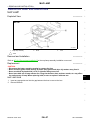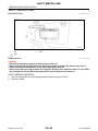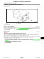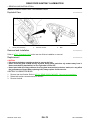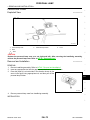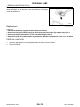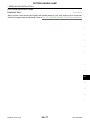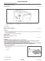
1
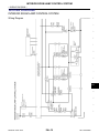
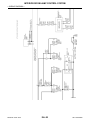
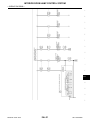
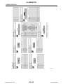
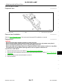
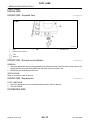
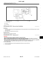
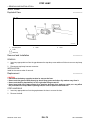
DRIVER CONTROLS
SECTION
INL
INTERIOR LIGHTING SYSTEM
A
B
C
D
E
CONTENTS
PRECAUTION ............................................... 3
PRECAUTIONS ................................................... 3
Precaution for Supplemental Restraint System
(SRS) "AIR BAG" and "SEAT BELT PRE-TENSIONER" ................................................................... 3
Precaution Necessary for Steering Wheel Rotation after Battery Disconnect ..................................... 3
SYSTEM DESCRIPTION .............................. 5
COMPONENT PARTS ........................................ 5
INTERIOR LIGHTING SYSTEM .................................. 5
INTERIOR LIGHTING SYSTEM : Component
Parts Location ........................................................... 5
INTERIOR LIGHTING SYSTEM :
Component Description ............................................ 5
SYSTEM .............................................................. 7
AUTO LIGHT ADJUSTMENT SYSTEM : System
Description ...............................................................12
DIAGNOSIS SYSTEM (BCM) ........................... 13
F
G
COMMON ITEM .........................................................13
COMMON ITEM : CONSULT-III Function (BCM COMMON ITEM) .....................................................13
H
INT LAMP ...................................................................14
INT LAMP : CONSULT-III Function (BCM - INT
LAMP) ......................................................................15
I
BATTERY SAVER .....................................................16
BATTERY SAVER : CONSULT-III Function (BCM
- BATTERY SAVER) ...............................................16
J
ECU DIAGNOSIS INFORMATION .............. 18
K
BCM ................................................................... 18
List of ECU Reference .............................................18
INTERIOR ROOM LAMP CONTROL SYSTEM .......... 7
INTERIOR ROOM LAMP CONTROL SYSTEM :
System Diagram ........................................................ 7
INTERIOR ROOM LAMP CONTROL SYSTEM :
System Description ................................................... 7
WIRING DIAGRAM ...................................... 19 INL
INTERIOR ROOM LAMP BATTERY SAVER SYSTEM .............................................................................. 9
INTERIOR ROOM LAMP BATTERY SAVER
SYSTEM : System Diagram .................................... 10
INTERIOR ROOM LAMP BATTERY SAVER
SYSTEM : System Description ............................... 10
ILLUMINATION ................................................. 35
ILLUMINATION CONTROL SYSTEM ....................... 11
ILLUMINATION CONTROL SYSTEM : System
Diagram ................................................................... 11
ILLUMINATION CONTROL SYSTEM : System
Description .............................................................. 11
AUTO LIGHT ADJUSTMENT SYSTEM .................... 11
AUTO LIGHT ADJUSTMENT SYSTEM : System
Diagram ................................................................... 12
Revision: 2010 June
INTERIOR ROOM LAMP CONTROL SYSTEM
... 19
M
Wiring Diagram ........................................................19
Wiring Diagram ........................................................35
N
BASIC INSPECTION ................................... 54
DIAGNOSIS AND REPAIR WORKFLOW ........ 54
O
Work Flow ................................................................54
DTC/CIRCUIT DIAGNOSIS ......................... 56
INTERIOR ROOM LAMP POWER SUPPLY
CIRCUIT ............................................................ 56
Description ...............................................................56
Component Function Check ....................................56
Diagnosis Procedure ...............................................56
INL-1
2011 M37/M56
P
INTERIOR ROOM LAMP CONTROL CIRCUIT
... 58
Description .............................................................. 58
Component Function Check ................................... 58
Diagnosis Procedure .............................................. 58
TRUNK ROOM LAMP CIRCUIT ........................ 60
REAR DOOR ASHTRAY ILLUMINATION ........ 70
Exploded View ........................................................ 70
Removal and Installation ......................................... 70
Replacement ........................................................... 70
GLOVE BOX LAMP ........................................... 71
Description .............................................................. 60
Diagnosis Procedure .............................................. 60
Exploded View ........................................................ 71
Removal and Installation ......................................... 71
Replacement ........................................................... 71
STEP LAMP CIRCUIT ....................................... 61
FOOT LAMP ...................................................... 72
Description .............................................................. 61
Component Function Check ................................... 61
Diagnosis Procedure .............................................. 61
OUTSIDE HANDLE LAMP CIRCUIT ................. 63
Description .............................................................. 63
Diagnosis Procedure .............................................. 63
PUSH-BUTTON IGNITION SWITCH ILLUMINATION CIRCUIT .............................................. 64
Description .............................................................. 64
Component Function Check ................................... 64
Diagnosis Procedure .............................................. 64
SYMPTOM DIAGNOSIS ............................. 66
INTERIOR LIGHTING SYSTEM SYMPTOMS ... 66
DRIVER SIDE ............................................................ 72
DRIVER SIDE : Exploded View .............................. 72
DRIVER SIDE : Removal and Installation ............... 72
DRIVER SIDE : Replacement ................................. 72
PASSENGER SIDE ................................................... 72
PASSENGER SIDE : Exploded View ..................... 73
PASSENGER SIDE : Removal and Installation ...... 73
PASSENGER SIDE : Replacement ........................ 73
STEP LAMP ....................................................... 74
Exploded View ........................................................ 74
Removal and Installation ......................................... 74
Replacement ........................................................... 74
PERSONAL LAMP ............................................ 75
REMOVAL AND INSTALLATION ............... 67
Exploded View ........................................................ 75
Removal and Installation ......................................... 75
Replacement ........................................................... 76
MAP LAMP ........................................................ 67
OUTSIDE HANDLE LAMP ................................ 77
Symptom Table ...................................................... 66
Exploded View ........................................................ 67
Removal and Installation ........................................ 67
Replacement .......................................................... 67
VANITY MIRROR LAMP ................................... 68
Exploded View ........................................................ 68
Replacement .......................................................... 68
Exploded View ........................................................ 77
TRUNK ROOM LAMP ....................................... 78
Exploded View ........................................................ 78
Removal and Installation ......................................... 78
Replacement ........................................................... 78
CIGARETTE LIGHTER ILLUMINATION ........... 69
SERVICE DATA AND SPECIFICATIONS
(SDS) .......................................................... 79
Exploded View ........................................................ 69
Removal and Installation ........................................ 69
Replacement .......................................................... 69
SERVICE DATA AND SPECIFICATIONS
(SDS) ................................................................. 79
bulb specifications ................................................
Revision: 2010 June
INL-2
2011 M37/M56
PRECAUTIONS
< PRECAUTION >
PRECAUTION
A
PRECAUTIONS
Precaution for Supplemental Restraint System (SRS) "AIR BAG" and "SEAT BELT
PRE-TENSIONER"
B
INFOID:0000000006108033
The Supplemental Restraint System such as “AIR BAG” and “SEAT BELT PRE-TENSIONER”, used along
with a front seat belt, helps to reduce the risk or severity of injury to the driver and front passenger for certain
types of collision. This system includes seat belt switch inputs and dual stage front air bag modules. The SRS
system uses the seat belt switches to determine the front air bag deployment, and may only deploy one front
air bag, depending on the severity of a collision and whether the front occupants are belted or unbelted.
Information necessary to service the system safely is included in the “SRS AIR BAG” and “SEAT BELT” of this
Service Manual.
WARNING:
• To avoid rendering the SRS inoperative, which could increase the risk of personal injury or death in
the event of a collision that would result in air bag inflation, all maintenance must be performed by
an authorized NISSAN/INFINITI dealer.
• Improper maintenance, including incorrect removal and installation of the SRS, can lead to personal
injury caused by unintentional activation of the system. For removal of Spiral Cable and Air Bag
Module, see the “SRS AIR BAG”.
• Do not use electrical test equipment on any circuit related to the SRS unless instructed to in this
Service Manual. SRS wiring harnesses can be identified by yellow and/or orange harnesses or harness connectors.
PRECAUTIONS WHEN USING POWER TOOLS (AIR OR ELECTRIC) AND HAMMERS
WARNING:
• When working near the Air Bag Diagnosis Sensor Unit or other Air Bag System sensors with the
ignition ON or engine running, DO NOT use air or electric power tools or strike near the sensor(s)
with a hammer. Heavy vibration could activate the sensor(s) and deploy the air bag(s), possibly
causing serious injury.
• When using air or electric power tools or hammers, always switch the ignition OFF, disconnect the
battery, and wait at least 3 minutes before performing any service.
C
D
E
F
G
H
I
J
Precaution Necessary for Steering Wheel Rotation after Battery Disconnect
INFOID:0000000006108034
K
NOTE:
• Before removing and installing any control units, first turn the push-button ignition switch to the LOCK posiINL
tion, then disconnect both battery cables.
• After finishing work, confirm that all control unit connectors are connected properly, then re-connect both
battery cables.
• Always use CONSULT-III to perform self-diagnosis as a part of each function inspection after finishing work. M
If a DTC is detected, perform trouble diagnosis according to self-diagnosis results.
For vehicle with steering lock unit, if the battery is disconnected or discharged, the steering wheel will lock and
cannot be turned.
If turning the steering wheel is required with the battery disconnected or discharged, follow the operation pro- N
cedure below before starting the repair operation.
OPERATION PROCEDURE
1.
2.
3.
4.
Connect both battery cables.
NOTE:
Supply power using jumper cables if battery is discharged.
Turn the push-button ignition switch to ACC position.
(At this time, the steering lock will be released.)
Disconnect both battery cables. The steering lock will remain released with both battery cables disconnected and the steering wheel can be turned.
Perform the necessary repair operation.
Revision: 2010 June
INL-3
2011 M37/M56
O
P
PRECAUTIONS
< PRECAUTION >
5. When the repair work is completed, re-connect both battery cables. With the brake pedal released, turn
the push-button ignition switch from ACC position to ON position, then to LOCK position. (The steering
wheel will lock when the push-button ignition switch is turned to LOCK position.)
6. Perform self-diagnosis check of all control units using CONSULT-III.
Revision: 2010 June
INL-4
2011 M37/M56
COMPONENT PARTS
< SYSTEM DESCRIPTION >
SYSTEM DESCRIPTION
A
COMPONENT PARTS
INTERIOR LIGHTING SYSTEM
B
INTERIOR LIGHTING SYSTEM : Component Parts Location
INFOID:0000000006054121
C
D
E
F
G
H
JMLIA1024ZZ
1.
4.
7.
Personal lamp
2.
IPDM E/R
Refer to PCS-5, "IPDM E/R : Component Parts Location"
5.
Outside handle lamp
8.
Remote keyless entry receiver
3.
Refer to DLK-9, "DOOR LOCK SYSTEM : Component Parts Location"
Optical sensor
BCM
Refer to BCS-4, "BODY CONTROL
SYSTEM : Component Parts Location"
6.
Door lock and unlock switch
Front door request switch (driver
side)
9.
I
J
Step lamp
K
10. Door switch
11. Front door lock assembly (driver
side) (door key cylinder switch, unlock sensor)
12. Trunk lid lock assembly (trunk room
lamp switch)
13. Trunk room lamp
14. Vanity mirror lamp
15. Combination meter
16. Combination switch
17. Foot lamp
18. Push-button ignition switch
19. AV control unit
Refer to AV-10, "Component Parts
Location"
20. Map lamp
INL
M
INTERIOR LIGHTING SYSTEM : Component Description
Part
INFOID:0000000006054122
Description
O
BCM
Controls the interior lighting system.
IPDM E/R
Controls the integrated relay according to the request signal from BCM (via CAN communication).
Remote keyless entry receiver
Receives the lock/unlock signal from Intelligent Key.
Combination switch
(Lighting & turn signal switch)
Refer to BCS-6, "COMBINATION SWITCH READING SYSTEM : System Description".
• Door lock and unlock switch
• Door request switch
• Door key cylinder switch
Inputs the lock/unlock signal to BCM.
Revision: 2010 June
INL-5
N
2011 M37/M56
P
COMPONENT PARTS
< SYSTEM DESCRIPTION >
Part
Description
Door switch
Inputs the door switch signal to BCM.
Trunk room lamp switch
Inputs the trunk room lamp switch signal to BCM.
Unlock sensor
Detects door lock condition of driver side door.
Optical sensor
Refer to EXL-8, "EXTERIOR LIGHTING SYSTEM : Component Description".
Revision: 2010 June
INL-6
2011 M37/M56
SYSTEM
< SYSTEM DESCRIPTION >
SYSTEM
A
INTERIOR ROOM LAMP CONTROL SYSTEM
INTERIOR ROOM LAMP CONTROL SYSTEM : System Diagram
INFOID:0000000006054123
B
C
D
E
F
G
H
I
J
JMLIA1025GB
INTERIOR ROOM LAMP CONTROL SYSTEM : System Description
INFOID:0000000006054124
K
OUTLINE
INL
• Interior room lamps* are controlled by interior room lamp timer control function of BCM.
*: Map lamp, foot lamp and personal lamp (when map lamp switch and personal lamp switch are in DOOR
position).
• Step lamp is controlled by step lamp control function of BCM.
M
• Trunk room lamp is controlled by trunk room lamp control function of BCM.
• Outside handle lamp is controlled by outside handle lamp timer control function of BCM.
• Push-button ignition switch illumination is controlled by the push-button ignition switch illumination control
N
function of BCM.
• Interior room lamps and outside handle lamp are illuminated by welcome light function of Intelligent Key system. Refer to DLK-23, "WELCOME LIGHT FUNCTION : System Description".
O
INTERIOR ROOM LAMP TIMER CONTROL
P
Revision: 2010 June
INL-7
2011 M37/M56
SYSTEM
< SYSTEM DESCRIPTION >
Interior Room Lamp Timer Basic Operation
JMLIA0961GB
NOTE:
A: Sets the interior room lamp gradual brightening and dimming time.
B: Gradually dims from 100% to 0% and gradually brightens 0% to 100% in 1 second.
• The interior room lamp turns ON and OFF (gradual brightening and dimming) by the interior room lamp
timer.
• BCM judges the vehicle condition with the following items. It activates the interior room timer.
- Ignition switch status
- Door switch signal
- Door lock/unlock signal (Remote keyless entry receiver, each door request switch, door key cylinder switch,
door lock/unlock switch)
NOTE:
Each function of interior room lamp timer can be set by CONSULT-III. Refer to INL-15, "INT LAMP : CONSULT-III Function (BCM - INT LAMP)".
Interior Room Lamp ON Operation
• BCM always turns the interior room lamp ON when any door opens.
• When all doors are closed, and any all door unlock operation is performed or ignition switch is turned OFF,
BCM brightens interior room lamp to 30% brightness and maintains 30% brightness until any door opens.
• BCM activates the interior room timer in any of the following conditions to turn the interior room lamp ON for
a period of time.
- Any door opens before all doors close.
- Ignition switch is turned ON → OFF.
- Any door unlock signal is detected when all doors close with ignition switch OFF.
NOTE:
The timer is restarted if new condition is input during the timer operating time.
Interior Room Lamp OFF Operation
BCM stops the timer in any of the following conditions to turns the interior room lamp OFF.
• The interior room lamp timer operating time is expired with all doors closed.
• Ignition switch position is other than OFF with all doors close.
• Any door lock operation is detected with all doors close.
TRUNK ROOM LAMP CONTROL
BCM controls the trunk room lamp (ground-side) to turn ON with trunk room lamp switch ON.
STEP LAMP CONTROL
BCM controls the step lamp (ground-side) to turn ON with any door switch ON.
OUTSIDE HANDLE LAMP TIMER CONTROL
Outside Handle Lamp Timer Basic Operation
• BCM controls the ground to turn the outside handle lamp ON.
• The outside handle lamp turns ON and OFF by the outside handle lamp timer.
• BCM judges the vehicle condition with the following items. It activates the outside handle lamp timer.
- Ignition switch status
- Door switch signal
- Door lock/unlock signal (remote keyless entry receiver, each door request switch)
Revision: 2010 June
INL-8
2011 M37/M56
SYSTEM
< SYSTEM DESCRIPTION >
- Driver side door lock status
Outside Handle Lamp ON Operation
BCM activates the outside handle lamp timer in any of the following conditions to turn the outside handle lamp
ON for a period of time.
• Any door opens.
• Any door opens before all doors close.
• Ignition switch is turned ON → OFF.
• Door unlock signal by remote keyless entry receiver or each door request switch is detected.
• Driver side door is locked
NOTE:
The timer is restarted if new condition is input during the timer operating time.
A
B
C
D
Outside Handle Lamp OFF Operation
BCM stops the timer in any of the following conditions to turns the outside handle lamp OFF.
• The outside handle lamp timer operating time is expired.
• The interior room lamp OFF conditions.
• The interior room lamp timer operating time is expired.
E
PUSH-BUTTON IGNITION SWITCH ILLUMINATION CONTROL
F
Push-button Ignition Switch Illumination Basic Operation
BCM controls the ON/OFF status of push-button ignition switch illumination according to vehicle status.
Heart Beat Operation
BCM repeats brightening and dimming operation of push-button ignition switch illumination when any of the
following conditions are satisfied.
• Welcome light function operates.
• When ignition switch is OFF and any of the following conditions are satisfied.
- Driver door changes from closed to open
- Intelligent Key ID comparison is OK and driver side door changes from open to closed
- ID comparison by Intelligent Key transponder is OK
- Driver door is unlocked
Illumination ON Operation
When ignition switch is change from OFF to ON, push-button ignition switch illumination turns ON.
Dimming Operation
When ignition switch is change from ON to OFF, driver side is open and driver side door unlocked, push-button ignition switch illumination dims to 50% brightness.
G
H
I
J
K
Illumination OFF Operation
Push-button ignition switch illumination turns OFF when ignition switch turns OFF, while push-button ignition INL
switch illumination is in ON status.
When push-button ignition switch illumination is at 50% brightness or, when in heartbeat status any of the following conditions are satisfied, push-button ignition switch illumination turns OFF.
M
• Driver side door from unlock to lock.
• 15 seconds after start of heartbeat operation.
• When welcome light function is not operating and any on the following conditions is satisfied.
- Driver side door is closed
N
- Intelligent Key ID comparison is NG
- Comparison of Intelligent Key ID by transponder is NG
INTERIOR ROOM LAMP BATTERY SAVER SYSTEM
O
P
Revision: 2010 June
INL-9
2011 M37/M56
SYSTEM
< SYSTEM DESCRIPTION >
INTERIOR ROOM LAMP BATTERY SAVER SYSTEM : System Diagram
INFOID:0000000006054125
JMLIA1026GB
INTERIOR ROOM LAMP BATTERY SAVER SYSTEM : System Description
INFOID:0000000006054126
OUTLINE
• Interior room lamp battery saver is controlled by BCM.
• BCM turns applicable lamps OFF depending on the vehicle condition. This function prevents the battery
from over-discharging if the driver neglect turning OFF the any lamps.
Applicable lamps
• Map lamp
• Personal lamp
• Foot lamp
• Trunk room lamp
• Step lamp
• Outside handle lamp
• Vanity mirror lamp
INTERIOR ROOM LAMP BATTERY SAVER FUNCTION
• When the ignition switch is turned is other position than ON, BCM operates the timer for a period of time to
cut the interior room lamp power supply.
• BCM restart the timer when any of the following signals changes while operating the timer.
- Ignition switch status
- Door switch signal (ALL)
- Door lock/unlock signal (remote keyless entry receiver, each door request switch, door lock and unlock
switch, door key cylinder switch)
• BCM provides the interior room lamp power supply continuously when the ignition switch position is ON.
• When welcome light function operates.
NOTE:
Revision: 2010 June
INL-10
2011 M37/M56
SYSTEM
< SYSTEM DESCRIPTION >
Each function of interior room lamp battery saver can be set by CONSULT-III. Refer to INL-16, "BATTERY
SAVER : CONSULT-III Function (BCM - BATTERY SAVER)".
A
ILLUMINATION CONTROL SYSTEM
ILLUMINATION CONTROL SYSTEM : System Diagram
INFOID:0000000006054127
B
C
D
E
F
JPLIA0855GB
ILLUMINATION CONTROL SYSTEM : System Description
G
INFOID:0000000006054128
OUTLINE
H
Each illumination lamp is controlled by each function of BCM and IPDM E/R.
Control by BCM
I
• Combination switch reading function
• Headlamp control function
Control by IPDM E/R
J
• Relay control function
Control by combination meter
• Meter illumination control function (Refer to MWI-13, "SPEEDOMETER : System Description".)
K
ILLUMINATION CONTROL
• BCM detects the combination switch condition by the combination switch reading function.
• BCM transmits position light request signal to IPDM E/R and combination meter according to tail lamp ON INL
condition.
Tail lamp ON condition
•
Lighting switch 1ST
Lighting switch 2ND
Lighting switch AUTO, and the auto light function ON judgment (With auto light system)
IPDM E/R turns the integrated tail lamp relay ON according to position light request signal. It provides the
power supply to each illumination lamp.
• Combination meter enters in the nighttime mode according to position light request signal. Under the nighttime mode the combination meter controls the illuminance by controlling the each illumination lamp (ground
side).
M
N
O
AUTO LIGHT ADJUSTMENT SYSTEM
P
Revision: 2010 June
INL-11
2011 M37/M56
SYSTEM
< SYSTEM DESCRIPTION >
AUTO LIGHT ADJUSTMENT SYSTEM : System Diagram
INFOID:0000000006054129
JMLIA0967GB
AUTO LIGHT ADJUSTMENT SYSTEM : System Description
INFOID:0000000006054130
OUTLINE
Auto light adjustment system is controlled by each function of BCM, combination meter and AV control unit
Control by BCM
• Auto light system
• Auto light adjustment system
AUTO LIGHT ADJUSTMENT SYSTEM
Description
• BCM supplies voltage to the optical sensor when the ignition switch is turned ON or ACC.
• Optical sensor converts outside brightness (lux) to voltage and transmits the optical sensor signal to BCM.
• BCM judges dims/brightness of combination meter and display according to brightness outside the vehicle,
when ignition switch is ON.
• BCM transmits dimmer signal to combination meter via CAN communication, according to auto light adjustment conditions. Dimmer signal is also transmitted to AV control unit.
NOTE:
As to dims/brightness timing, the sensitivity depends on settings. The settings can be changed with CONSULT-III. Refer to EXL-25, "HEADLAMP : CONSULT-III Function (BCM - HEAD LAMP)".
Auto Light Adjustment Timing Table
When the ignition switch is ON, the combination meter and display turns dims/brightness in the following condition.
Combination meter and display
Dims/brightness timing
Dims
Outside brightness is 1250 lx or less for 3 seconds or more.
Brightness
Outside brightness is 2500 lx or more for 5 seconds or more.
BCM turns combination meter and display dims when outside brightness obtained from the optical sensor signal is 1250 lx or less for 3 seconds or more. And BCM turns combination meter and display brightness when
outside brightness from the optical sensor signal is 2500 lx or more for 5 seconds or more.
Revision: 2010 June
INL-12
2011 M37/M56
DIAGNOSIS SYSTEM (BCM)
< SYSTEM DESCRIPTION >
DIAGNOSIS SYSTEM (BCM)
A
COMMON ITEM
COMMON ITEM : CONSULT-III Function (BCM - COMMON ITEM)
INFOID:0000000006109638
B
APPLICATION ITEM
CONSULT-III performs the following functions via CAN communication with BCM.
C
Diagnosis mode
Function Description
Work Support
Changes the setting for each system function.
Self Diagnostic Result
Displays the diagnosis results judged by BCM.
CAN Diag Support Monitor
Monitors the reception status of CAN communication viewed from BCM. Refer to CONSULT-III operation manual.
Data Monitor
The BCM input/output signals are displayed.
Active Test
The signals used to activate each device are forcibly supplied from BCM.
Ecu Identification
The BCM part number is displayed.
Configuration
• Read and save the vehicle specification.
• Write the vehicle specification when replacing BCM.
D
E
F
G
SYSTEM APPLICATION
BCM can perform the following functions for each system.
NOTE:
It can perform the diagnosis modes except the following for all sub system selection items.
H
×: Applicable item
System
Sub system selection item
Diagnosis mode
Work Support
Data Monitor
Active Test
×
×
×
Door lock
DOOR LOCK
Rear window defogger
REAR DEFOGGER
×
×
Warning chime
BUZZER
×
×
Interior room lamp timer
INT LAMP
×
×
×
Exterior lamp
HEAD LAMP
×
×
×
Wiper and washer
WIPER
×
×
×
Turn signal and hazard warning lamps
FLASHER
×
×
×
×
×
×
×
—
AIR CONDITONER*
• Intelligent Key system
• Engine start system
INTELLIGENT KEY
Combination switch
COMB SW
×
Body control system
BCM
×
IVIS - NATS
IMMU
×
×
×
Interior room lamp battery saver
BATTERY SAVER
×
×
×
Trunk lid open
TRUNK
Vehicle security system
THEFT ALM
RAP system
RETAINED PWR
×
Signal buffer system
SIGNAL BUFFER
×
×
×
×
×
*: This item is not used.
FREEZE FRAME DATA (FFD)
The BCM records the following vehicle condition at the time a particular DTC is detected, and displays on
CONSULT-III.
Revision: 2010 June
INL-13
J
K
INL
M
×
×
I
2011 M37/M56
N
O
P
DIAGNOSIS SYSTEM (BCM)
< SYSTEM DESCRIPTION >
CONSULT screen item
Indication/Unit
Description
Vehicle Speed
km/h
Vehicle speed of the moment a particular DTC is detected
Odo/Trip Meter
km
Total mileage (Odometer value) of the moment a particular DTC is detected
SLEEP>LOCK
While turning BCM status from low power consumption mode to
normal mode (Power supply position is “LOCK”)
SLEEP>OFF
While turning BCM status from low power consumption mode to
normal mode (Power supply position is “OFF”.)
LOCK>ACC
While turning power supply position from “LOCK” to “ACC”
ACC>ON
While turning power supply position from “ACC” to “IGN”
RUN>ACC
While turning power supply position from “RUN” to “ACC” (Vehicle
is stopping and selector lever is except P position.)
CRANK>RUN
While turning power supply position from “CRANKING” to “RUN”
(From cranking up the engine to run it)
RUN>URGENT
While turning power supply position from “RUN“ to “ACC” (Emergency stop operation)
ACC>OFF
While turning power supply position from “ACC” to “OFF”
OFF>LOCK
Vehicle Condition
OFF>ACC
ON>CRANK
IGN Counter
While turning power supply position from “OFF” to “LOCK”
Power position status of
the moment a particular
DTC is detected
While turning power supply position from “OFF” to “ACC”
While turning power supply position from “IGN” to “CRANKING”
OFF>SLEEP
While turning BCM status from normal mode (Power supply position is “OFF”.) to low power consumption mode
LOCK>SLEEP
While turning BCM status from normal mode (Power supply position is “LOCK”.) to low power consumption mode
LOCK
Power supply position is “LOCK” (Ignition switch OFF with steering is locked.)
OFF
Power supply position is “OFF” (Ignition switch OFF with steering
is unlocked.)
ACC
Power supply position is “ACC” (Ignition switch ACC)
ON
Power supply position is “IGN” (Ignition switch ON with engine
stopped)
ENGINE RUN
Power supply position is “RUN” (Ignition switch ON with engine
running)
CRANKING
Power supply position is “CRANKING” (At engine cranking)
0 - 39
The number of times that ignition switch is turned ON after DTC is detected
• The number is 0 when a malfunction is detected now.
• The number increases like 1 → 2 → 3...38 → 39 after returning to the normal condition
whenever ignition switch OFF → ON.
• The number is fixed to 39 until the self-diagnosis results are erased if it is over 39.
INT LAMP
Revision: 2010 June
INL-14
2011 M37/M56
DIAGNOSIS SYSTEM (BCM)
< SYSTEM DESCRIPTION >
INT LAMP : CONSULT-III Function (BCM - INT LAMP)
INFOID:0000000006054132
A
WORK SUPPORT
B
C
D
E
JMLIA0961GB
Service item
SET I/L D-UNLCK INTCON
ROOM LAMP TIMER SET
ROOM LAMP ON TIME SET
ROOM LAMP OFF TIME SET
R LAMP TIMER LOGIC SET
Setting item
F
Setting
On*
With the interior room lamp timer function
Off
Without the interior room lamp timer function
MODE 2
7.5 sec.
MODE 3*
15 sec.
MODE 4
30 sec.
G
Sets the interior room lamp ON time. (Timer operating time)
MODE 1
0.5 sec.
MODE 2
1 sec.
MODE 3
2 sec.
MODE 4
3 sec.
MODE 5
0 sec.
MODE 6*
Gradually brightens from 0% to 100% brightness in 1 second.
MODE 1
0.5 sec.
MODE 2
1 sec.
MODE 3
2 sec.
MODE 4
3 sec.
MODE 5
0 sec.
MODE 6*
Gradually dims from 100% to 0% in 1 second.
MODE 1*
Interior room lamp timer activates with synchronizing all doors.
MODE 2
Interior room lamp timer activates with synchronizing the driver door only.
H
I
Sets the interior room lamp gradual brightening time.
J
Sets the interior room lamp gradual dimming time.
K
INL
M
N
*: Factory setting
DATA MONITOR
O
Monitor item
[Unit]
Description
P
REQ SW-DR
[On/Off]
The switch status input from request switch (driver side)
REQ SW-AS
[On/Off]
The switch status input from request switch (passenger side)
Revision: 2010 June
INL-15
2011 M37/M56
DIAGNOSIS SYSTEM (BCM)
< SYSTEM DESCRIPTION >
Monitor item
[Unit]
Description
REQ SW-RR
[On/Off]
NOTE:
The item is indicated, but not monitored.
REQ SW-RL
[On/Off]
PUSH SW
[On/Off]
Push switch status received from Intelligent Key unit via CAN communication
UNLK SEN -DR
[On/Off]
Driver door unlock status input from unlock sensor
DOOR SW-DR
[On/Off]
The switch status input from front door switch (driver side)
DOOR SW-AS
[On/Off]
The switch status input from front door switch (passenger side)
DOOR SW-RR
[On/Off]
The switch status input from rear door switch RH
DOOR SW- RL
[On/Off]
The switch status input from rear door switch LH
DOOR SW- BK
[On/Off]
NOTE:
The item is indicated, but not monitored.
CDL LOCK SW
[On/Off]
Lock switch status input from door lock and unlock switch
CDL UNLOCK SW
[On/Off]
Unlock switch status input from door lock and unlock switch
KEY CYL LK-SW
[On/Off]
Lock switch status received from key cylinder lock/unlock switch
KEY CYL UN-SW
[On/Off]
Unlock switch status received from key cylinder lock/unlock switch
TRNK/HAT MNTR
[On/Off]
The switch status input from trunk room lamp switch
RKE-LOCK
[On/Off]
Lock signal status received from remote keyless entry receiver
RKE-UNLOCK
[On/Off]
Unlock signal status received from remote keyless entry receiver
ACTIVE TEST
Test item
INT LAMP
STEP LAMP TEST
Operation
Description
On
Outputs the interior room lamp control signal to turn the interior room lamps ON.
[Map lamp, personal lamp, foot lamp (when applicable lamps switch is in DOOR position.)]
Off
Stops the interior room lamp control signal to turn the interior room lamps OFF.
On
Outputs the step lamp control signal to turn the step lamps ON.
Off
Stops the step lamp control signal to turn the step lamps ON.
BATTERY SAVER
BATTERY SAVER : CONSULT-III Function (BCM - BATTERY SAVER)
INFOID:0000000006054133
WORK SUPPORT
Service item
ROOM LAMP TIMER SET
Revision: 2010 June
Setting item
Setting
MODE 1*
30 min.
MODE 2
60 min.
INL-16
Sets the interior room lamp battery saver timer operating
time.
2011 M37/M56
DIAGNOSIS SYSTEM (BCM)
< SYSTEM DESCRIPTION >
Service item
Setting item
BATTERY SAVER SET
Setting
On*
With the exterior lamp battery saver function
Off
Without the exterior lamp battery saver function
A
B
*:Factory setting
DATA MONITOR
C
Monitor item
[Unit]
Description
REQ SW-DR
[On/Off]
The switch status input from request switch (driver side)
REQ SW-AS
[On/Off]
The switch status input from front request switch (passenger side)
D
E
REQ SW-RR
[On/Off]
NOTE:
The item is indicated, but not monitored.
REQ SW-RL
[On/Off]
F
PUSH SW
[On/Off]
Push switch status received from Intelligent Key unit by CAN communication
UNLK SEN-DR
[On/Off]
Driver door unlock status input from unlock sensor
DOOR SW-DR
[On/Off]
The switch status input from front door switch (driver side)
DOOR SW-AS
[On/Off]
The switch status input from front door switch (passenger side)
DOOR SW-RR
[On/Off]
The switch status input from rear door switch RH
DOOR SW- RL
[On/Off]
The switch status input from rear door switch LH
DOOR SW- BK
[On/Off]
NOTE:
The item is indicated, but not monitored.
CDL LOCK SW
[On/Off]
Lock switch status input from door lock and unlock switch
CDL UNLOCK SW
[On/Off]
Unlock switch status input from door lock and unlock switch
KEY CYL LK-SW
[On/Off]
Lock switch status received from key cylinder lock/unlock switch
KEY CYL UN-SW
[On/Off]
Unlock switch status received from key cylinder lock/unlock switch
TRNK/HAT MNTR
[On/Off]
The switch status input from trunk room lamp switch
RKE-LOCK
[On/Off]
Lock signal status received from remote keyless entry receiver
RKE-UNLOCK
[On/Off]
Unlock signal status received from remote keyless entry receiver
G
H
I
J
K
INL
M
N
O
ACTIVE TEST
P
Test item
Operation
BATTERY SAVER
Description
Off
Cuts the interior room lamp power supply to turn interior room lamps OFF.
On
Outputs the interior room lamp power supply to turn interior room lamps ON.*
*: Each lamp switch is in ON position.
Revision: 2010 June
INL-17
2011 M37/M56
BCM
< ECU DIAGNOSIS INFORMATION >
ECU DIAGNOSIS INFORMATION
BCM
List of ECU Reference
INFOID:0000000006054134
ECU
Reference
BCS-32, "Reference Value"
BCM
BCS-52, "Fail-safe"
BCS-54, "DTC Inspection Priority Chart"
BCS-55, "DTC Index"
Revision: 2010 June
INL-18
2011 M37/M56
INTERIOR ROOM LAMP CONTROL SYSTEM
< WIRING DIAGRAM >
WIRING DIAGRAM
A
INTERIOR ROOM LAMP CONTROL SYSTEM
Wiring Diagram
INFOID:0000000006054135
B
C
D
E
F
G
H
I
J
K
INL
M
N
O
P
JCLWA4164GB
Revision: 2010 June
INL-19
2011 M37/M56
INTERIOR ROOM LAMP CONTROL SYSTEM
< WIRING DIAGRAM >
JCLWA4165GB
Revision: 2010 June
INL-20
2011 M37/M56
INTERIOR ROOM LAMP CONTROL SYSTEM
< WIRING DIAGRAM >
A
B
C
D
E
F
G
H
I
J
K
INL
M
N
O
JCLWA4166GB
P
Revision: 2010 June
INL-21
2011 M37/M56
INTERIOR ROOM LAMP CONTROL SYSTEM
< WIRING DIAGRAM >
JCLWA4167GB
Revision: 2010 June
INL-22
2011 M37/M56
INTERIOR ROOM LAMP CONTROL SYSTEM
< WIRING DIAGRAM >
A
B
C
D
E
F
G
H
I
J
K
INL
M
N
O
JCLWA4168GB
P
Revision: 2010 June
INL-23
2011 M37/M56
INTERIOR ROOM LAMP CONTROL SYSTEM
< WIRING DIAGRAM >
JCLWA4169GB
Revision: 2010 June
INL-24
2011 M37/M56
INTERIOR ROOM LAMP CONTROL SYSTEM
< WIRING DIAGRAM >
A
B
C
D
E
F
G
H
I
J
K
INL
M
N
O
JCLWA4170GB
P
Revision: 2010 June
INL-25
2011 M37/M56
INTERIOR ROOM LAMP CONTROL SYSTEM
< WIRING DIAGRAM >
JCLWA4171GB
Revision: 2010 June
INL-26
2011 M37/M56
INTERIOR ROOM LAMP CONTROL SYSTEM
< WIRING DIAGRAM >
A
B
C
D
E
F
G
H
I
J
K
INL
M
N
O
JCLWA4172GB
P
Revision: 2010 June
INL-27
2011 M37/M56
INTERIOR ROOM LAMP CONTROL SYSTEM
< WIRING DIAGRAM >
JCLWA4173GB
Revision: 2010 June
INL-28
2011 M37/M56
INTERIOR ROOM LAMP CONTROL SYSTEM
< WIRING DIAGRAM >
A
B
C
D
E
F
G
H
I
J
K
INL
M
N
O
JCLWA4174GB
P
Revision: 2010 June
INL-29
2011 M37/M56
INTERIOR ROOM LAMP CONTROL SYSTEM
< WIRING DIAGRAM >
JCLWA4175GB
Revision: 2010 June
INL-30
2011 M37/M56
INTERIOR ROOM LAMP CONTROL SYSTEM
< WIRING DIAGRAM >
A
B
C
D
E
F
G
H
I
J
K
INL
M
N
O
JCLWA4176GB
P
Revision: 2010 June
INL-31
2011 M37/M56
INTERIOR ROOM LAMP CONTROL SYSTEM
< WIRING DIAGRAM >
JCLWA4177GB
Revision: 2010 June
INL-32
2011 M37/M56
INTERIOR ROOM LAMP CONTROL SYSTEM
< WIRING DIAGRAM >
A
B
C
D
E
F
G
H
I
J
K
INL
M
N
O
JCLWA4178GB
P
Revision: 2010 June
INL-33
2011 M37/M56
INTERIOR ROOM LAMP CONTROL SYSTEM
< WIRING DIAGRAM >
JCLWA4179GB
Revision: 2010 June
INL-34
2011 M37/M56
ILLUMINATION
< WIRING DIAGRAM >
ILLUMINATION
A
Wiring Diagram
INFOID:0000000006054136
B
C
D
E
F
G
H
I
J
K
INL
M
N
O
P
JCLWA4180GB
Revision: 2010 June
INL-35
2011 M37/M56
ILLUMINATION
< WIRING DIAGRAM >
JCLWA4181GB
Revision: 2010 June
INL-36
2011 M37/M56
ILLUMINATION
< WIRING DIAGRAM >
A
B
C
D
E
F
G
H
I
J
K
INL
M
N
O
JCLWA4182GB
P
Revision: 2010 June
INL-37
2011 M37/M56
ILLUMINATION
< WIRING DIAGRAM >
JCLWA4183GB
Revision: 2010 June
INL-38
2011 M37/M56
ILLUMINATION
< WIRING DIAGRAM >
A
B
C
D
E
F
G
H
I
J
K
INL
M
N
O
JCLWA4184GB
P
Revision: 2010 June
INL-39
2011 M37/M56
ILLUMINATION
< WIRING DIAGRAM >
JCLWA4185GB
Revision: 2010 June
INL-40
2011 M37/M56
ILLUMINATION
< WIRING DIAGRAM >
A
B
C
D
E
F
G
H
I
J
K
INL
M
N
O
JCLWA4186GB
P
Revision: 2010 June
INL-41
2011 M37/M56
ILLUMINATION
< WIRING DIAGRAM >
JCLWA4187GB
Revision: 2010 June
INL-42
2011 M37/M56
ILLUMINATION
< WIRING DIAGRAM >
A
B
C
D
E
F
G
H
I
J
K
INL
M
N
O
JCLWA4188GB
P
Revision: 2010 June
INL-43
2011 M37/M56
ILLUMINATION
< WIRING DIAGRAM >
JCLWA4189GB
Revision: 2010 June
INL-44
2011 M37/M56
ILLUMINATION
< WIRING DIAGRAM >
A
B
C
D
E
F
G
H
I
J
K
INL
M
N
O
JCLWA4190GB
P
Revision: 2010 June
INL-45
2011 M37/M56
ILLUMINATION
< WIRING DIAGRAM >
JCLWA4191GB
Revision: 2010 June
INL-46
2011 M37/M56
ILLUMINATION
< WIRING DIAGRAM >
A
B
C
D
E
F
G
H
I
J
K
INL
M
N
O
JCLWA4192GB
P
Revision: 2010 June
INL-47
2011 M37/M56
ILLUMINATION
< WIRING DIAGRAM >
JCLWA4193GB
Revision: 2010 June
INL-48
2011 M37/M56
ILLUMINATION
< WIRING DIAGRAM >
A
B
C
D
E
F
G
H
I
J
K
INL
M
N
O
JCLWA4194GB
P
Revision: 2010 June
INL-49
2011 M37/M56
ILLUMINATION
< WIRING DIAGRAM >
JCLWA4195GB
Revision: 2010 June
INL-50
2011 M37/M56
ILLUMINATION
< WIRING DIAGRAM >
A
B
C
D
E
F
G
H
I
J
K
INL
M
N
O
JCLWA4196GB
P
Revision: 2010 June
INL-51
2011 M37/M56
ILLUMINATION
< WIRING DIAGRAM >
JCLWA4197GB
Revision: 2010 June
INL-52
2011 M37/M56
ILLUMINATION
< WIRING DIAGRAM >
A
B
C
D
E
F
G
H
I
J
K
INL
M
N
O
JCLWA4198GB
P
Revision: 2010 June
INL-53
2011 M37/M56
DIAGNOSIS AND REPAIR WORKFLOW
< BASIC INSPECTION >
BASIC INSPECTION
DIAGNOSIS AND REPAIR WORKFLOW
Work Flow
INFOID:0000000006054137
OVERALL SEQUENCE
JPLIA0313GB
DETAILED FLOW
1.INTERVIEW FOR MALFUNCTION
Interview the symptom to the customer.
Revision: 2010 June
INL-54
2011 M37/M56
DIAGNOSIS AND REPAIR WORKFLOW
< BASIC INSPECTION >
>> GO TO 2.
2.SYMPTOM CHECK
A
Check the symptom from the customer's information.
B
>> GO TO 3.
3.BASIC INSPECTION
Check the operation of each part. Check that any symptom occurs other than the interviewed symptom.
>> GO TO 4.
C
D
4.SELF-DIAGNOSIS WITH CONSULT-III
Perform the self-diagnosis with CONSULT-III. Check that any DTC is detected.
Is any DTC detected?
YES >> GO TO 5.
NO
>> GO TO 6.
E
F
5.TROUBLE DIAGNOSIS BY DTC
Perform the trouble diagnosis for the detected DTC. Specify the malfunctioning part.
G
>> GO TO 9.
6.FAIL-SAFE ACTIVATION CHECK
H
Check that the symptom is applied to the fail-safe activation.
Does the fail-safe activate?
YES >> GO TO 7.
NO
>> GO TO 8.
I
7.SYSTEM DIAGNOSIS
Perform the system diagnosis for the system that the fail-safe activates. Specify the malfunctioning part.
>> GO TO 9.
J
K
8.SYMPTOM DIAGNOSIS
Perform the symptom diagnosis. Specify the malfunctioning part.
INL
>> GO TO 9.
9.MALFUNCTION PART REPAIR
M
Repair or replace the malfunctioning part.
N
>> GO TO 10.
10.REPAIR CHECK (SELF-DIAGNOSIS WITH CONSULT-III)
Perform the self-diagnosis with CONSULT-III. Check that any DTC is not detected. Erase DTC if DTC is
detected before the repair. Check that DTC is not detected again.
Is any DTC detected?
YES >> GO TO 5.
NO
>> GO TO 11.
11.REPAIR CHECK (OPERATION CHECK)
Check the operation of each part.
Does it operate normally?
YES >> INSPECTION END
NO
>> GO TO 3.
Revision: 2010 June
INL-55
2011 M37/M56
O
P
INTERIOR ROOM LAMP POWER SUPPLY CIRCUIT
< DTC/CIRCUIT DIAGNOSIS >
DTC/CIRCUIT DIAGNOSIS
INTERIOR ROOM LAMP POWER SUPPLY CIRCUIT
Description
INFOID:0000000006054138
Provides the interior room lamp power supply. Also cuts the power supply when the interior room lamp battery
saver activating.
Component Function Check
INFOID:0000000006054139
1.CHECK INTERIOR ROOM LAMP POWER SUPPLY FUNCTION
1.
2.
3.
4.
CONSULT-III ACTIVE TEST
Turn ignition switch ON.
Turn each interior room lamp ON.
Personal lamp
Map lamp
Foot lamp
Trunk room lamp
Step lamp
Outside handle lamp
Vanity mirror lamp
Select “BATTERY SAVER” of BCM (BATTERY SAVER) active test item.
With operating the test items, check that each interior room lamp turns ON/OFF.
Off
On
: Interior room lamp OFF
: Interior room lamp ON
Does the interior room lamp turn ON/OFF?
YES >> Interior room lamp power supply circuit is normal.
NO
>> Refer to INL-56, "Diagnosis Procedure".
Diagnosis Procedure
INFOID:0000000006054140
1.CHECK INTERIOR ROOM LAMP POWER SUPPLY OUTPUT
1.
2.
3.
4.
5.
CONSULT-III ACTIVE TEST
Turn ignition switch OFF.
Disconnect the following connectors.
Personal lamp
Map lamp
Foot lamp (both sides)
Trunk room lamp
Step lamp (ALL)
Outside handle lamp (both sides)
Vanity mirror lamp (both sides)
Turn ignition switch ON.
Select “BATTERY SAVER” of BCM (BATTERY SAVER) active test item.
With operating the test item, check voltage between BCM harness connector and ground.
BCM
(+)
(–)
Connector
Terminal
M122
56
Ground
Voltage
(Approx.)
Test item
BATTERY SAVER
Off
0V
On
12 V
Is the inspection result normal?
YES >> GO TO 2.
NO
>> GO TO 3.
Revision: 2010 June
INL-56
2011 M37/M56
INTERIOR ROOM LAMP POWER SUPPLY CIRCUIT
< DTC/CIRCUIT DIAGNOSIS >
2.CHECK INTERIOR ROOM LAMP POWER SUPPLY OPEN CIRCUIT
1.
2.
3.
A
Turn ignition switch OFF.
Disconnect the BCM connector.
Check continuity between BCM harness connector and each interior room lamp harness connector.
BCM
Connector
M122
Each interior room lamp
Terminal
56
Connector
Terminal
Personal lamp
R14
Map lamp
R15
Foot lamp
(driver side)
M186
Foot lamp
(passenger side)
M114
Trunk room lamp
B47
Step lamp
(driver side)
D12
Step lamp
(passenger side)
D42
Step lamp
(Rear LH)
D57
Step lamp
(Rear RH)
D77
Outside handle lamp
(driver side)
D17
Outside handle lamp
(passenger side)
D47
Vanity mirror lamp (driver side)
R12
Vanity mirror lamp (passenger
side)
R13
Continuity
C
D
E
1
F
Existed
G
H
3
I
2
J
Is the inspection result normal?
YES >> Check for internal short circuit of each interior room lamp.
NO
>> Repair or replace harnesses.
K
3.CHECK INTERIOR ROOM LAMP POWER SUPPLY SHORT CIRCUIT
1.
2.
3.
INL
Turn ignition switch OFF.
Disconnect the BCM connector.
Check continuity between BCM harness connector and ground.
BCM
Connector
Terminal
M122
56
B
Ground
M
Continuity
Not existed
Is the inspection result normal?
YES >> Replace BCM. Refer to BCS-79, "Removal and Installation".
NO
>> Repair or replace harnesses.
N
O
P
Revision: 2010 June
INL-57
2011 M37/M56
INTERIOR ROOM LAMP CONTROL CIRCUIT
< DTC/CIRCUIT DIAGNOSIS >
INTERIOR ROOM LAMP CONTROL CIRCUIT
Description
INFOID:0000000006054141
Controls each interior room lamp (ground side) by PWM signal.
NOTE:
PWM signal control period is approximately 250 Hz (in the gradual brightening/dimming).
Component Function Check
INFOID:0000000006054142
CAUTION:
Before performing the diagnosis, check that the following is normal.
• Interior room lamp power supply
• Map lamp bulb
• Personal lamp bulb
• Foot lamp bulb
1.CHECK INTERIOR ROOM LAMP CONTROL FUNCTION
1.
2.
3.
4.
CONSULT-III ACTIVE TEST
Switch the map lamp switch to DOOR.
Turn ignition switch ON.
Select “INT LAMP” of BCM (INT LAMP) active test item.
With operating the test items, check that each interior room lamp turns ON/OFF (gradual brightening/dimming).
On
Off
: Interior room lamp gradual brightening
: Interior room lamp gradual dimming
Does the interior room lamp turns ON/OFF (gradual brightening/dimming)?
YES >> Interior room lamp control circuit is normal.
NO
>> Refer to INL-58, "Diagnosis Procedure".
Diagnosis Procedure
INFOID:0000000006054143
1.CHECK INTERIOR ROOM LAMP CONTROL OUTPUT
1.
2.
3.
4.
5.
CONSULT-III ACTIVE TEST
Turn ignition switch OFF.
Remove all the bulbs of map lamp, foot lamp and personal lamp.
Turn ignition switch ON.
Select “INT LAMP” of BCM (INT LAMP) active test item.
With operating the test item, check continuity between BCM harness connector and ground.
BCM
Connector
Terminal
M122
63
Test item
Ground
INT LAMP
Continuity
On
Existed
Off
Not existed
Is the inspection result normal?
YES >> GO TO 2.
Fixed ON>>GO TO 3.
Fixed OFF>>Replace BCM. Refer to BCS-79, "Removal and Installation".
2.CHECK INTERIOR ROOM LAMP CONTROL OPEN CIRCUIT
1.
2.
3.
Turn ignition switch OFF.
Disconnect BCM connector, map lamp connector, personal lamp connector and foot lamp connector.
Check continuity between BCM harness connector and foot lamp harness connector.
Revision: 2010 June
INL-58
2011 M37/M56
INTERIOR ROOM LAMP CONTROL CIRCUIT
< DTC/CIRCUIT DIAGNOSIS >
BCM
4.
Foot lamp
Connector
Terminal
M122
63
Connector
Driver side
M186
Passenger side
M114
2
Continuity
Existed
B
C
Map lamp
Connector
Terminal
Connector
Terminal
M122
63
R15
2
Continuity
Existed
D
Check continuity between personal lamp harness connector and map lamp harness connector.
Personal lamp
Map lamp
Connector
Terminal
Connector
Terminal
R14
3
R15
4
Continuity
F
G
3.CHECK INTERIOR ROOM LAMP CONTROL SHORT CIRCUIT
Turn ignition switch OFF.
Disconnect BCM connector, map lamp connector, personal lamp connector and foot lamp connector.
Check continuity between BCM harness connector and ground.
BCM
Connector
Terminal
M122
63
E
Existed
Is the inspection result normal?
YES >> Replace map lamp, personal lamp or foot lamp.
NO
>> Repair or replace harnesses.
1.
2.
3.
A
Check continuity between BCM harness connector and map lamp harness connector.
BCM
5.
Terminal
Ground
Continuity
H
I
Not existed
J
Is the inspection result normal?
YES >> Replace BCM. Refer to BCS-79, "Removal and Installation".
NO
>> Repair or replace harnesses.
K
INL
M
N
O
P
Revision: 2010 June
INL-59
2011 M37/M56
TRUNK ROOM LAMP CIRCUIT
< DTC/CIRCUIT DIAGNOSIS >
TRUNK ROOM LAMP CIRCUIT
Description
INFOID:0000000006109635
Controls the trunk room lamp (ground side) to turn the trunk room lamp ON and OFF.
Diagnosis Procedure
INFOID:0000000006054145
CAUTION:
Before performing the diagnosis, check that the following is normal.
• Interior room lamp power supply
• trunk room lamp bulb
1.CHECK TRUNK ROOM LAMP OUTPUT
1.
2.
3.
Turn ignition switch OFF.
Remove the trunk room lamp bulb.
Check continuity between BCM harness connector and ground.
BCM
Connector
Terminal
M121
49
Condition
Ground
Trunk lid
Continuity
Open
Existed
Closed
Not existed
Is the inspection result normal?
YES >> GO TO 2.
Fixed ON>>GO TO 3.
Fixed OFF>>Replace BCM. Refer to BCS-79, "Removal and Installation".
2.CHECK TRUNK ROOM LAMP OPEN CIRCUIT
1.
2.
Disconnect BCM connector.
Check continuity between BCM harness connector and trunk room lamp harness connector.
BCM
Connector
Trunk room lamp
(+)
M121
(-)
Connector
Terminal
49
Continuity
Terminal
B47
2
Existed
Is the inspection result normal?
YES >> Replace trunk room lamp.
NO
>> Repair or replace harnesses.
3.CHECK TRUNK ROOM LAMP SHORT CIRCUIT
1.
2.
Disconnect BCM connector.
Check continuity between BCM harness connector and ground.
BCM
Connector
Terminal
M121
49
Ground
Continuity
Not existed
Is the inspection result normal?
YES >> Replace BCM. Refer to BCS-79, "Removal and Installation".
NO
>> Repair or replace harnesses.
Revision: 2010 June
INL-60
2011 M37/M56
STEP LAMP CIRCUIT
< DTC/CIRCUIT DIAGNOSIS >
STEP LAMP CIRCUIT
A
Description
INFOID:0000000006054146
Controls the step lamp (ground side) to turn the step lamp ON and OFF.
B
Component Function Check
INFOID:0000000006054147
CAUTION:
Before performing the diagnosis, check that the following is normal.
• Interior room lamp power supply
• Step lamp bulb
C
D
1.CHECK STEP LAMP OPERATION
1.
2.
3.
CONSULT-III ACTIVE TEST
Turn ignition switch ON.
Select “STEP LAMP TEST” of BCM (INT LAMP) active test item.
With operating the test items, check that step lamp turns ON/OFF.
On
Off
E
F
: Step lamp ON
: Step lamp OFF
G
Does the step lamp turn ON/OFF?
YES >> Step lamp circuit is normal.
NO
>> Refer to INL-61, "Diagnosis Procedure".
H
Diagnosis Procedure
INFOID:0000000006054148
1.CHECK STEP LAMP OUTPUT
I
CONSULT-III ACTIVE TEST
1. Turn ignition switch OFF.
2. Remove the step lamp bulbs (ALL).
3. Turn ignition switch ON.
4. Select “STEP LAMP TEST” of BCM (INT LAMP) active test item.
5. With operating the test item, check continuity between BCM harness connector and ground.
J
K
BCM
Connector
Terminal
M122
62
Test item
Ground
STEP LAMP TEST
Continuity
On
Existed
Off
Not existed
Is the inspection result normal?
YES >> GO TO 2.
Fixed ON>>GO TO 3.
Fixed OFF>>Replace BCM. Refer to BCS-79, "Removal and Installation".
M
N
2.CHECK STEP LAMP OPEN CIRCUIT
1.
2.
3.
Turn ignition switch OFF.
Disconnect BCM connector, and step lamp connector.
Check continuity between BCM harness connector and step lamp harness connector.
BCM
Connector
Step lamp
Terminal
Connector
Driver side
M122
Revision: 2010 June
62
Terminal
O
Continuity
D12
Passenger side
D42
Rear LH
D57
Rear RH
D77
INL-61
INL
2
Existed
2011 M37/M56
P
STEP LAMP CIRCUIT
< DTC/CIRCUIT DIAGNOSIS >
Is the inspection result normal?
YES >> Replace step lamp.
NO
>> Repair or replace harnesses.
3.CHECK STEP LAMP SHORT CIRCUIT
1.
2.
3.
Turn ignition switch OFF.
Disconnect BCM connector.
Check continuity between BCM harness connector and ground.
BCM
Connector
Terminal
M122
62
Ground
Continuity
Not existed
Is the inspection result normal?
YES >> Repair or replace harnesses.
NO
>> Replace BCM. Refer to BCS-79, "Removal and Installation".
Revision: 2010 June
INL-62
2011 M37/M56
OUTSIDE HANDLE LAMP CIRCUIT
< DTC/CIRCUIT DIAGNOSIS >
OUTSIDE HANDLE LAMP CIRCUIT
A
Description
INFOID:0000000006054149
Controls the outside handle lamp (ground side) to turn the outside handle lamp ON and OFF.
B
Diagnosis Procedure
INFOID:0000000006054150
CAUTION:
Before performing the diagnosis, check that the following is normal.
• Interior room lamp power supply
C
1.CHECK OUTSIDE HANDLE LAMP OUTPUT
D
1.
2.
3.
E
Turn ignition switch OFF.
Disconnect outside handle lamp connector.
Check continuity between BCM harness connector and ground.
BCM
Connector
Terminal
M123
72
Condition
Ground
Any door
Continuity
Open
Existed
Closed
Not existed
F
G
Is the inspection result normal?
YES >> GO TO 2.
Fixed ON>>GO TO 3.
Fixed OFF>>Replace BCM. Refer to BCS-79, "Removal and Installation".
H
2.CHECK OUTSIDE HANDLE LAMP OPEN CIRCUIT
Check continuity between BCM harness connector and outside handle lamp harness connector.
BCM
Outside Handle lamp
Connector
Terminal
M123
72
Connector
Terminal
Driver side
D17
Passenger side
D47
4
Continuity
I
J
Existed
K
Is the inspection result normal?
YES >> Replace outside handle lamp.
NO
>> Repair or replace harnesses.
INL
3.CHECK OUTSIDE HANDLE LAMP SHORT CIRCUIT
Check continuity between BCM harness connector and ground.
M
BCM
Connector
Terminal
M123
72
Ground
Continuity
Not existed
Is the inspection result normal?
YES >> Replace BCM. Refer to BCS-79, "Removal and Installation".
NO
>> Repair or replace harnesses.
N
O
P
Revision: 2010 June
INL-63
2011 M37/M56
PUSH-BUTTON IGNITION SWITCH ILLUMINATION CIRCUIT
< DTC/CIRCUIT DIAGNOSIS >
PUSH-BUTTON IGNITION SWITCH ILLUMINATION CIRCUIT
Description
INFOID:0000000006054151
Provides the power supply and the ground to control the push-button ignition switch illumination.
Component Function Check
INFOID:0000000006054152
1.CHECK PUSH-BUTTON IGNITION SWITCH ILLUMINATION OPERATION
1.
2.
3.
CONSULT-III ACTIVE TEST
Turn the ignition switch ON.
Select “ENGINE SW ILLUMI” of BCM (INTELLIGENT KEY) active test item.
With operating the test items, check that the push-button ignition switch illumination turns ON/OFF.
On
Off
: Push-button ignition switch illumination ON
: Push-button ignition switch illumination OFF
Does the push-button ignition switch illumination turn ON/OFF?
YES >> Push-button ignition switch illumination circuit is normal.
NO
>> Refer to INL-64, "Diagnosis Procedure".
Diagnosis Procedure
INFOID:0000000006054153
1.CHECK PUSH-BUTTON IGNITION SWITCH ILLUMINATION POWER SUPPLY OUTPUT
1.
2.
3.
Turn ignition switch OFF.
Disconnect push-button ignition switch connector.
Check voltage between push-button ignition switch harness connector and ground.
(+)
Push-button ignition switch
(–)
Connector
Terminal
M50
3
Ground
Voltage
(Approx.)
Condition
Push-button ignition switch
illumination
ON
12 V
OFF
0V
Is the inspection result normal?
YES >> GO TO 4.
NO
>> GO TO 2.
2.CHECK PUSH-BUTTON IGNITION SWITCH ILLUMINATION POWER SUPPLY OPEN CIRCUIT
1.
2.
3.
Turn the ignition switch OFF.
Disconnect BCM connector.
Check continuity between BCM harness connector and the push-button ignition switch harness connector.
BCM
Push-button ignition switch
Connector
Terminal
Connector
Terminal
M123
90
M50
3
Continuity
Existed
Is the inspection result normal?
YES >> GO TO 3.
NO
>> Repair or replace harnesses.
3.CHECK PUSH-BUTTON IGNITION SWITCH ILLUMINATION POWER SUPPLY SHORT CIRCUIT
Check continuity between BCM harness connector and ground.
BCM
Connector
Terminal
M123
90
Revision: 2010 June
Ground
Continuity
Not existed
INL-64
2011 M37/M56
PUSH-BUTTON IGNITION SWITCH ILLUMINATION CIRCUIT
< DTC/CIRCUIT DIAGNOSIS >
Is the inspection result normal?
YES >> Replace BCM. Refer to BCS-79, "Removal and Installation".
NO
>> Repair or replace harnesses.
A
4.CHECK PUSH-BUTTON IGNITION SWITCH ILLUMINATION GROUND CIRCUIT
1.
2.
Turn the ignition switch OFF.
Check continuity between push-button ignition switch harness connector and BCM harness connector.
Push-button ignition switch
3.
B
C
BCM
Connector
Terminal
Connector
Terminal
M50
2
M123
92
Continuity
Existed
D
Check continuity between push-button ignition switch harness connector and ground.
Push-button ignition switch
Connector
Terminal
M50
2
Ground
Continuity
E
Not existed
F
Is the inspection result normal?
YES >> Replace push-button ignition switch.
NO
>> Repair or replace harnesses.
G
H
I
J
K
INL
M
N
O
P
Revision: 2010 June
INL-65
2011 M37/M56
INTERIOR LIGHTING SYSTEM SYMPTOMS
< SYMPTOM DIAGNOSIS >
SYMPTOM DIAGNOSIS
INTERIOR LIGHTING SYSTEM SYMPTOMS
Symptom Table
INFOID:0000000006054154
CAUTION:
Perform the self-diagnosis with CONSULT-III before the symptom diagnosis. Perform the trouble diagnosis if any DTC is detected.
Symptom
Possible cause
All the following lamps do not turn ON.
• Map lamp
• Personal lamp
• Vanity mirror lamp
• Foot lamp
• Step lamp
• Outside handle lamp
• Trunk room lamp
• Harness between BCM and each
interior room lamp
• BCM
• Interior room lamp does not turn ON even
though the door is open.
(It turns ON when turning the interior room
lamp ON.)
• Interior room lamp does not turn OFF even
though the door is closed.
• Harness between BCM and each
door switch
• Harness between BCM and each
interior room lamp
• BCM
Interior room lamp timer does not activate.
(It turns ON/ OFF when the door opens/closes.)
—
Inspection item
Interior room lamp power supply circuit
Refer to INL-56.
Door switch circuit
Refer to DLK-72.
Interior room lamp control circuit
Refer to INL-58.
Check the interior room lamp setting.
Refer to INL-15.
Door switch circuit
Refer to DLK-72.
• Outside handle lamp does not turn ON even
though the door is open.
• Outside handle lamp does not turn OFF even
though the door is closed.
• Harness between BCM and each
door switch
• Harness between BCM and outside handle lamp
• BCM
• Trunk room lamp does not turn ON even
though the trunk lid is open.
(It turns ON when turning the trunk room lamp
ON.)
• Trunk room lamp or does not turn OFF even
though the trunk lid is closed.
• Harness between BCM and trunk
room lamp switch
• Harness between BCM and trunk
room lamp
• BCM
• Step lamps (ALL) do not turn ON.
• Step lamps (ALL) do not turn OFF.
• Harness between BCM and each
step lamp
• BCM
Push-button ignition switch illumination does not
illuminate.
• Harness between BCM and pushbutton ignition switch
• BCM
Push-button ignition switch illumination circuit
Refer to INL-64.
Interior room lamp battery saver does not activate.
BCM
Replace BCM.
Refer to BCS-79.
Revision: 2010 June
INL-66
Outside handle lamp circuit
Refer to INL-63.
Trunk room lamp switch circuit
Refer to DLK-86.
Trunk room lamp circuit
Refer to INL-60.
Door switch circuit
Refer to DLK-72.
Step lamp circuit
Refer to INL-61.
2011 M37/M56
MAP LAMP
< REMOVAL AND INSTALLATION >
REMOVAL AND INSTALLATION
A
MAP LAMP
Exploded View
INFOID:0000000006112928
B
C
D
E
F
JMLIA0808ZZ
1.
Map lamp assembly
2.
Bulb
3.
G
Lens
H
: Pawl
Removal and Installation
INFOID:0000000006112929
I
Refer to INT-49, "Removal and Installation" for the map lamp assembly installation or removal.
Replacement
INFOID:0000000006112930
J
CAUTION:
• Disconnect the battery negative terminal or remove the fuse.
• Never touch the glass of bulb directly by hand. Keep grease and other oily matters away from it.
• Never touch bulb by hand while it is lit or right after being turned off.
• Never leave bulb out of lamp reflector for a long time because dust, moisture smoke, etc. may affect
the performance of lamp. When replacing bulb, be sure to replace it with new one.
INL
MAP LAMP BULB
1.
2.
K
Insert any appropriate tool into the gap between the lens to remove the lens.
Remove the bulb.
M
N
O
P
Revision: 2010 June
INL-67
2011 M37/M56
VANITY MIRROR LAMP
< REMOVAL AND INSTALLATION >
VANITY MIRROR LAMP
Exploded View
INFOID:0000000006112931
JMLIA0540ZZ
1.
Lens
2.
Bulb
: Pawl
Replacement
INFOID:0000000006112932
CAUTION:
• Disconnect the battery negative terminal or remove the fuse.
• Never touch the glass of bulb directly by hand. Keep grease and other oily matters away from it.
• Never touch bulb by hand while it is lit or right after being turned off.
• Never leave bulb out of lamp reflector for a long time because dust, moisture smoke, etc. may affect
the performance of lamp. When replacing bulb, be sure to replace it with new one.
VANITY MIRROR LAMP BULB
1.
2.
Insert any appropriate tool into the gap between the lens to remove the lens.
Remove the bulb.
Revision: 2010 June
INL-68
2011 M37/M56
CIGARETTE LIGHTER ILLUMINATION
< REMOVAL AND INSTALLATION >
CIGARETTE LIGHTER ILLUMINATION
Exploded View
A
INFOID:0000000006112933
B
C
D
E
F
JMLIA0812ZZ
1.
Bulb
2.
G
Bulb socket
: Vehicle front
Removal and Installation
INFOID:0000000006115715
• Remove console finisher assembly. Refer to IP-24, "Removal and Installation". Removeal and Installation.
• Remove ashtray assembly. Refer to IP-24, "Removal and Installation". Disassembly and assembly of center
console assembly.
Replacement
H
I
INFOID:0000000006112934
J
CAUTION:
• Disconnect the battery negative terminal or remove the fuse.
• Never touch the glass of bulb directly by hand. Keep grease and other oily matters away from it.
• Never touch bulb by hand while it is lit or right after being turned off.
• Never leave bulb out of lamp reflector for a long time because dust, moisture smoke, etc. may affect
the performance of lamp. When replacing bulb, be sure to replace it with new one.
INL
CIGRETTE LIGHTER ILLUMINATION BULB
1.
2.
3.
K
Remove console finisher assembly, and then remove ashtray assembly. Refer to IP-24, "Removal and
Installation".
Rotate bulb socket counterclockwise to unlock it.
Remove the bulb.
M
N
O
P
Revision: 2010 June
INL-69
2011 M37/M56
REAR DOOR ASHTRAY ILLUMINATION
< REMOVAL AND INSTALLATION >
REAR DOOR ASHTRAY ILLUMINATION
Exploded View
INFOID:0000000006114061
JMLIA1087ZZ
1.
Ashtray lamp assembly
2.
Rear door finisher
3.
Bulb
Removal and Installation
INFOID:0000000006115716
Refer to INT-33, "Exploded View" for the rear door finisher installation or removal.
Replacement
INFOID:0000000006114062
CAUTION:
• Disconnect the battery negative terminal or remove the fuse.
• Never touch the glass of bulb directly by hand. Keep grease and other oily matters away from it.
Never touch bulb by hand while it is lit or right after it turns OFF.
• Never leave bulb out of lamp reflector for a long time because dust, moisture, smoke, etc. may affect
the performance of lamp. When replacing bulb, always replace it with new one.
ASHTRAY ILLUMINATION BULB
1.
2.
3.
Remove rear door finisher. Refer to INT-33, "REAR DOOR FINISHER : Removal and Installation".
Rotate bulb socket counterclockwise to unlock it.
Remove the bulb.
Revision: 2010 June
INL-70
2011 M37/M56
GLOVE BOX LAMP
< REMOVAL AND INSTALLATION >
GLOVE BOX LAMP
A
Exploded View
INFOID:0000000006112935
B
C
D
E
F
JMLIA1090ZZ
1.
Bulb socket
2.
Bulb
3.
Instrument lower panel RH
Removal and Installation
G
INFOID:0000000006115717
H
Refer to IP-12, "Exploded View" for the instrument lower panel RH installation or removal.
Replacement
INFOID:0000000006112936
I
CAUTION:
• Disconnect the battery negative terminal or remove the fuse.
• Never touch the glass of bulb directly by hand. Keep grease and other oily matters away from it.
• Never touch bulb by hand while it is lit or right after being turned off.
• Never leave bulb out of lamp reflector for a long time because dust, moisture smoke, etc. may affect
the performance of lamp. When replacing bulb, be sure to replace it with new one.
K
GLOVE BOX LAMP BULB
1.
2.
3.
4.
J
Remove instrument lower cover. Refer to IP-13, "Removal and Installation".
Remove glove box assembly, and then remove instrument lower panel RH. Refer to IP-13, "Removal and INL
Installation".
Rotate the bulb socket counterclockwise to unlock it.
Remove the bulb.
M
N
O
P
Revision: 2010 June
INL-71
2011 M37/M56
FOOT LAMP
< REMOVAL AND INSTALLATION >
FOOT LAMP
DRIVER SIDE
DRIVER SIDE : Exploded View
INFOID:0000000006112937
JMLIA1088ZZ
1.
Lens
4.
Instrument lower panel LH
2.
Bulb
3.
Foot lamp case
: Pawl
: Metal clip
DRIVER SIDE : Removal and Installation
INFOID:0000000006112938
REMOVAL
1.
2.
Insert any appropriate tool into the gap between the instrument lower panel LH and foot lamp case to disengage the foot lamp case fixing metal clips, and then remove foot lamp case.
Disconnect foot lamp harness connector.
INSTALLATION
Install in the reverse order of removal.
DRIVER SIDE : Replacement
INFOID:0000000006112939
FOOT LAMP BULB
1.
2.
Insert any appropriate tool into the gap between the lens. Remove the lens.
Remove the bulb.
PASSENGER SIDE
Revision: 2010 June
INL-72
2011 M37/M56
FOOT LAMP
< REMOVAL AND INSTALLATION >
PASSENGER SIDE : Exploded View
INFOID:0000000006112940
A
B
C
D
E
JMLIA1089ZZ
1.
Instrument lower cover
4.
Foot lamp case
2.
Lens
3.
F
Bulb
G
: Pawl
: Metal clip
PASSENGER SIDE : Removal and Installation
H
INFOID:0000000006112941
REMOVAL
1.
2.
I
Insert any appropriate tool into the gap between the instrument lower cover and foot lamp case to remove
foot lamp case.
Disconnect foot lamp harness connector.
J
INSTALLATION
Install in the reverse order of removal.
K
PASSENGER SIDE : Replacement
INFOID:0000000006112942
CAUTION:
INL
• Disconnect the battery negative terminal or remove the fuse.
• Never touch the glass of bulb directly by hand. Keep grease and other oily matters away from it.
• Never touch bulb by hand while it is lit or right after being turned off.
• Never leave bulb out of lamp reflector for a long time because dust, moisture smoke, etc. may affect M
the performance of lamp. When replacing bulb, be sure to replace it with new one.
FOOT LAMP BULB
1.
2.
N
Insert any appropriate tool into the gap between the lens to remove the lens.
Remove the bulb.
O
P
Revision: 2010 June
INL-73
2011 M37/M56
STEP LAMP
< REMOVAL AND INSTALLATION >
STEP LAMP
Exploded View
INFOID:0000000006112943
JMLIA0541ZZ
1.
Step lamp case
2.
Bulb
3.
Lens
: Pawl
: Metal clip
Removal and Installation
INFOID:0000000006112944
REMOVAL
1.
2.
Insert any appropriate tool into the gap between the step lamp case and door finisher to remove step lamp
case.
Disconnect step lamp harness connector.
INSTALLATION
Install in the reverse order of removal.
Replacement
INFOID:0000000006112945
CAUTION:
• Disconnect the battery negative terminal or remove the fuse.
• Never touch the glass of bulb directly by hand. Keep grease and other oily matters away from it.
• Never touch bulb by hand while it is lit or right after being turned off.
• Never leave bulb out of lamp reflector for a long time because dust, moisture smoke, etc. may affect
the performance of lamp. When replacing bulb, be sure to replace it with new one.
STEP LAMP BULB
1.
2.
Insert any appropriate tool into the gap between the lens to remove the lens.
Remove the bulb.
Revision: 2010 June
INL-74
2011 M37/M56
PERSONAL LAMP
< REMOVAL AND INSTALLATION >
PERSONAL LAMP
A
Exploded View
INFOID:0000000006112946
B
C
D
E
F
JMLIA0542ZZ
1.
4.
Personal lamp case
2.
Personal lamp finisher
3.
G
Lens
Bulb
: Pawl
H
CAUTION:
Replace the personal lamp case as a set (right and left). After removing the headlining assembly,
remove the personal lamp case. Refer to INT-48, "Exploded View".
Removal and Installation
INFOID:0000000006112947
J
REMOVAL
1.
2.
3.
I
Remove headlining assembly. Refer to INT-49, "Removal and Installation".
Insert any appropriate tool into the gap between the lens to remove the lens.
Press the pawls (A) on both sides in the direction shown by the
arrow in the figure using appropriate tool, and then pull out the
personal lamp finisher.
K
INL
M
N
JPLIA0087ZZ
4.
Remove personal lamp case from headlining assembly.
O
INSTALLATION
P
Revision: 2010 June
INL-75
2011 M37/M56
PERSONAL LAMP
< REMOVAL AND INSTALLATION >
Press the personal lamp finisher to the headlining. Pull the personal
lamp case pawls in the direction shown by the arrow in the figure
using appropriate tool.
JPLIA0937ZZ
Replacement
INFOID:0000000006112948
CAUTION:
• Disconnect the battery negative terminal or remove the fuse.
• Never touch the glass of bulb directly by hand. Keep grease and other oily matters away from it.
• Never touch bulb by hand while it is lit or right after being turned off.
• Never leave bulb out of lamp reflector for a long time because dust, moisture smoke, etc. may affect
the performance of lamp. When replacing bulb, be sure to replace it with new one.
PERSONAL LAMP BLUB
1.
2.
Insert any appropriate tool into the gap between the lens to remove the lens.
Remove the bulb.
Revision: 2010 June
INL-76
2011 M37/M56
OUTSIDE HANDLE LAMP
< REMOVAL AND INSTALLATION >
OUTSIDE HANDLE LAMP
A
Exploded View
INFOID:0000000006115297
Always replace outside handle lamp together with outside handle as a set, when replacing since outside handle lamp is integrated with outside handle. Refer to DLK-176, "OUTSIDE HANDLE : Removal and Installation".
B
C
D
E
F
G
H
I
J
K
INL
M
N
O
P
Revision: 2010 June
INL-77
2011 M37/M56
TRUNK ROOM LAMP
< REMOVAL AND INSTALLATION >
TRUNK ROOM LAMP
Exploded View
INFOID:0000000006112949
JMLIA0813ZZ
1.
Trunk room lamp case
2.
Blub
3.
Lens
: Pawl
: Metal clip
Removal and Installation
INFOID:0000000006112950
REMOVAL
1.
2.
Insert any appropriate tool into the gap between the trunk room lamp case and trunk finisher front to
remove trunk room lamp case.
Disconnect trunk room lamp harness connector.
INSTALLATION
Install in the reverse order of removal.
Replacement
INFOID:0000000006112951
CAUTION:
• Disconnect the battery negative terminal or remove the fuse.
• Never touch the glass of bulb directly by hand. Keep grease and other oily matters away from it.
• Never touch bulb by hand while it is lit or right after being turned off.
• Never leave bulb out of lamp reflector for a long time because dust, moisture smoke, etc. may affect
the performance of lamp. When replacing bulb, be sure to replace it with new one.
TRUNK ROOM LAMP BULB
1.
Insert any appropriate tool into the gap between the lens to
remove the lens.
: Pawl
JMLIA0807ZZ
2.
Remove the bulb.
Revision: 2010 June
INL-78
2011 M37/M56
SERVICE DATA AND SPECIFICATIONS (SDS)
< SERVICE DATA AND SPECIFICATIONS (SDS)
SERVICE DATA AND SPECIFICATIONS (SDS)
A
SERVICE DATA AND SPECIFICATIONS (SDS)
bulb specifications
Item
Push-button ignition switch illumination
Map lamp
Console lamp
(integrated into the map lamp assembly)
Vanity mirror lamp
INFOID:0000000006113379
Type
Wattage (W)
LED
—
—
8
LED
—
—
2
Cigarette lighter illumination
(common use with ashtray illumination)
Wedge
1.1
Rear door ashtray illumination
Wedge
2
Glove box lamp
Wedge
2
Foot lamp
Wedge
3.4
Step lamp
Wedge
5
Personal lamp
Wedge
8
LED
—
Wedge
5
Outside handle lamp
Trunk room lamp
B
C
D
E
F
G
H
I
J
K
INL
M
N
O
P
Revision: 2010 June
INL-79
2011 M37/M56