1
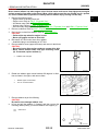
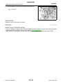
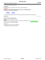
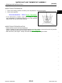
ENGINE
SECTION
CO
ENGINE COOLING SYSTEM
A
CO
C
D
E
CONTENTS
VQ35HR
F
SYSTEM DESCRIPTION .............................. 3
Exploded View .........................................................14
Removal and Installation .........................................14
Inspection ................................................................16
DESCRIPTION .................................................... 3
COOLING FAN .................................................. 17
Engine Cooling System ........................................... 3
Engine Cooling System Schematic ......................... 3
H
SYMPTOM DIAGNOSIS ............................... 4
Exploded View .........................................................17
Removal and Installation .........................................17
Disassembly and Assembly .....................................17
Inspection ................................................................18
OVERHEATING CAUSE ANALYSIS .................. 4
WATER PUMP .................................................. 19
Troubleshooting Chart .............................................. 4
Exploded View .........................................................19
Removal and Installation .........................................19
Inspection ................................................................21
I
PRECAUTION ............................................... 6
PRECAUTIONS ................................................... 6
Precaution for Supplemental Restraint System
(SRS) "AIR BAG" and "SEAT BELT PRE-TENSIONER" ................................................................... 6
Exploded View .........................................................22
Removal and Installation .........................................22
Inspection ................................................................23
K
WATER OUTLET AND WATER PIPING .......... 24
L
Exploded View .........................................................24
Removal and Installation .........................................24
Inspection ................................................................25
M
SERVICE DATA AND SPECIFICATIONS
(SDS) ............................................................ 26
N
Commercial Service Tools ....................................... 7
PERIODIC MAINTENANCE .......................... 8
ENGINE COOLANT ............................................ 8
Inspection .................................................................. 8
Draining ..................................................................... 8
Refilling ..................................................................... 9
Flushing ................................................................... 10
SERVICE DATA AND SPECIFICATIONS
(SDS) ................................................................. 26
Periodical Maintenance Specification ....................26
Radiator ...................................................................26
Thermostat ..............................................................26
RADIATOR .........................................................12
RADIATOR CAP ........................................................ 12
RADIATOR CAP : Inspection .................................. 12
RADIATOR ................................................................ 12
RADIATOR : Inspection .......................................... 12
VK50VE
DESCRIPTION .................................................. 27
Engine Cooling System ..........................................27
Engine Cooling System Schematic .......................28
RADIATOR .........................................................14
CO-1
O
P
SYSTEM DESCRIPTION ............................. 27
REMOVAL AND INSTALLATION ............... 14
Revision: 2009 March
J
WATER INLET AND THERMOSTAT ASSEMBLY .................................................................... 22
PREPARATION ............................................ 7
PREPARATION ................................................... 7
G
2009 FX35/FX50
SYMPTOM DIAGNOSIS ............................. 29
REMOVAL AND INSTALLATION .............. 39
OVERHEATING CAUSE ANALYSIS ................ 29
RADIATOR ........................................................ 39
Troubleshooting Chart ........................................... 29
PRECAUTION ............................................. 31
Exploded View ........................................................ 39
Removal and Installation ......................................... 39
Inspection ................................................................ 41
PRECAUTIONS ................................................. 31
COOLING FAN .................................................. 42
Precaution for Supplemental Restraint System
(SRS) "AIR BAG" and "SEAT BELT PRE-TENSIONER" ................................................................. 31
Exploded View ........................................................ 42
Removal and Installation ......................................... 42
Disassembly and Assembly .................................... 42
Inspection ................................................................ 43
PREPARATION ........................................... 32
PREPARATION ................................................. 32
Commercial Service Tools .................................... 32
PERIODIC MAINTENANCE ........................ 33
ENGINE COOLANT ........................................... 33
Inspection ............................................................... 33
Draining .................................................................. 33
Refilling ................................................................... 34
Flushing .................................................................. 35
RADIATOR ........................................................ 37
RADIATOR CAP ....................................................... 37
RADIATOR CAP : Inspection ................................. 37
RADIATOR ................................................................ 37
RADIATOR : Inspection .......................................... 37
Revision: 2009 March
WATER PUMP ................................................... 44
Exploded View ........................................................ 44
Removal and Installation ......................................... 44
Inspection ................................................................ 45
WATER INLET AND THERMOSTAT ASSEMBLY .................................................................... 46
Exploded View ........................................................ 46
Removal and Installation ......................................... 46
Inspection ................................................................ 47
SERVICE DATA AND SPECIFICATIONS
(SDS) .......................................................... 49
SERVICE DATA AND SPECIFICATIONS
(SDS) ................................................................. 49
Periodical Maintenance Specification .................... 49
Radiator .................................................................. 49
Thermostat .............................................................. 49
CO-2
2009 FX35/FX50
DESCRIPTION
[VQ35HR]
< SYSTEM DESCRIPTION >
SYSTEM DESCRIPTION
A
DESCRIPTION
Engine Cooling System
INFOID:0000000003890718
CO
C
D
E
F
G
H
I
JPBIA1198GB
J
Engine Cooling System Schematic
INFOID:0000000003890719
K
L
M
N
O
P
JPBIA1199GB
Revision: 2009 March
CO-3
2009 FX35/FX50
OVERHEATING CAUSE ANALYSIS
[VQ35HR]
< SYMPTOM DIAGNOSIS >
SYMPTOM DIAGNOSIS
OVERHEATING CAUSE ANALYSIS
Troubleshooting Chart
INFOID:0000000003890720
Symptom
Check items
Water pump malfunction
Worn or loose drive belt
Thermostat stuck closed
Poor heat transfer
—
Dust contamination or paper clogging
Damaged fins
—
Physical damage
Clogged radiator cooling
tube
Excess foreign material
(rust, dirt, sand, etc.)
Cooling fan does not operate
Reduced air flow
High resistance to fan rotation
Fan assembly
—
Damaged fan blades
Cooling system parts
malfunction
Damaged radiator shroud
—
—
—
Improper engine coolant
mixture ratio
—
—
—
Poor engine coolant quality
—
Engine coolant density
Cooling hose
Water pump
Radiator cap
Engine coolant leakage
—
Loose clamp
Cracked hose
Poor sealing
Loose
Poor sealing
O-ring for damage, deterioration or improper fitting
Insufficient engine coolant
Radiator
Cracked radiator tank
Cracked radiator core
Reservoir tank
Overflowing reservoir tank
Revision: 2009 March
CO-4
Exhaust gas leakage into
cooling system
Cracked reservoir tank
Cylinder head deterioration
Cylinder head gasket deterioration
2009 FX35/FX50
OVERHEATING CAUSE ANALYSIS
[VQ35HR]
< SYMPTOM DIAGNOSIS >
Symptom
Check items
High engine rpm under no
load
Abusive driving
Driving in low gear for extended time
A
CO
Driving at extremely high
speed
—
Overload on engine
Installed improper size
wheels and tires
Except cooling system
parts malfunction
C
Powertrain system malfunction
—
D
Dragging brakes
Improper ignition timing
Blocked bumper
E
—
Installed car brassiere
Blocked radiator grille
Blocked or restricted air
flow
Blocked radiator
Mud contamination or paper
clogging
F
—
—
Blocked condenser
Installed large fog lamp
G
Blocked air flow
H
I
J
K
L
M
N
O
P
Revision: 2009 March
CO-5
2009 FX35/FX50
PRECAUTIONS
[VQ35HR]
< PRECAUTION >
PRECAUTION
PRECAUTIONS
Precaution for Supplemental Restraint System (SRS) "AIR BAG" and "SEAT BELT
PRE-TENSIONER"
INFOID:0000000005188066
The Supplemental Restraint System such as “AIR BAG” and “SEAT BELT PRE-TENSIONER”, used along
with a front seat belt, helps to reduce the risk or severity of injury to the driver and front passenger for certain
types of collision. This system includes seat belt switch inputs and dual stage front air bag modules. The SRS
system uses the seat belt switches to determine the front air bag deployment, and may only deploy one front
air bag, depending on the severity of a collision and whether the front occupants are belted or unbelted.
Information necessary to service the system safely is included in the “SRS AIR BAG” and “SEAT BELT” of this
Service Manual.
WARNING:
• To avoid rendering the SRS inoperative, which could increase the risk of personal injury or death in
the event of a collision which would result in air bag inflation, all maintenance must be performed by
an authorized NISSAN/INFINITI dealer.
• Improper maintenance, including incorrect removal and installation of the SRS, can lead to personal
injury caused by unintentional activation of the system. For removal of Spiral Cable and Air Bag
Module, see the “SRS AIR BAG”.
• Do not use electrical test equipment on any circuit related to the SRS unless instructed to in this
Service Manual. SRS wiring harnesses can be identified by yellow and/or orange harnesses or harness connectors.
PRECAUTIONS WHEN USING POWER TOOLS (AIR OR ELECTRIC) AND HAMMERS
WARNING:
• When working near the Air Bag Diagnosis Sensor Unit or other Air Bag System sensors with the
ignition ON or engine running, DO NOT use air or electric power tools or strike near the sensor(s)
with a hammer. Heavy vibration could activate the sensor(s) and deploy the air bag(s), possibly
causing serious injury.
• When using air or electric power tools or hammers, always switch the ignition OFF, disconnect the
battery, and wait at least 3 minutes before performing any service.
Revision: 2009 March
CO-6
2009 FX35/FX50
PREPARATION
[VQ35HR]
< PREPARATION >
PREPARATION
A
PREPARATION
Commercial Service Tools
INFOID:0000000003890722
Tool name
Description
Power tool
Loosening bolts and nuts
CO
C
D
E
PBIC0190E
Radiator cap tester
Checking radiator and radiator cap
F
G
PBIC1982E
Radiator cap tester adapter
Adapting radiator cap tester to radiator cap
and water outlet (front) filler neck
a: 28 (1.10) dia.
b: 31.4 (1.236) dia.
c: 41.3 (1.626) dia.
Unit: mm (in)
H
I
J
S-NT564
K
L
M
N
O
P
Revision: 2009 March
CO-7
2009 FX35/FX50
ENGINE COOLANT
[VQ35HR]
< PERIODIC MAINTENANCE >
PERIODIC MAINTENANCE
ENGINE COOLANT
Inspection
INFOID:0000000003890723
LEVEL
• Check if the reservoir tank engine coolant level is within the “MIN”
to “MAX” when the engine is cool.
A
: MAX
B
: MIN
• Adjust the engine coolant level as necessary.
• Check that the reservoir tank cap is tightened.
JPBIA0102ZZ
LEAKAGE
• To check for leakage, apply pressure to the cooling system with the
radiator cap tester and radiator cap tester adapter (commercial
service tool) (A).
Testing pressure
: Refer to CO-49, "Radiator".
WARNING:
Never remove radiator cap when engine is hot. Serious burns
could occur from high-pressure engine coolant escaping from
water outlet (front).
CAUTION:
Higher test pressure than specified may cause radiator damage.
NOTE:
In a case that engine coolant decreases, fill radiator with engine coolant.
• If anything is found, repair or replace damaged parts.
Draining
JPBIA0411ZZ
INFOID:0000000003890724
WARNING:
• Never change engine coolant when the engine is hot to avoid being scalded.
• Wrap a thick cloth around radiator cap and carefully remove radiator cap. First, turn radiator cap a
quarter of a turn to release built-up pressure. Then turn radiator cap all the way.
1. Open radiator drain plug (2) at the bottom of radiator, and then
remove radiator cap.
1
: Engine under cover
A
: Radiator drain plug hole
: Vehicle front
JPBIA0259ZZ
When draining all of engine coolant in the system, open water drain plugs on cylinder block. Refer
to EM-92, "Setting".
2.
3.
Remove reservoir tank as necessary, and drain engine coolant and clean reservoir tank before installing.
Check drained engine coolant for contaminants such as rust, corrosion or discoloration.
Revision: 2009 March
CO-8
2009 FX35/FX50
ENGINE COOLANT
< PERIODIC MAINTENANCE >
If contaminated, flush the engine cooling system. Refer to CO-10, "Flushing".
A
Refilling
1.
2.
[VQ35HR]
INFOID:0000000003890725
Remove engine cover. Refer to EM-27, "Exploded View".
Install reservoir tank if removed, and radiator drain plug.
CAUTION:
Be sure to clean drain plug and install with new O-ring.
CO
C
Tightening torque
3.
4.
: Refer to CO-14, "Exploded View".
If water drain plugs on cylinder block are removed, close and tighten them. Refer to EM-118, "Disassembly and Assembly".
Check that each hose clamp is firmly tightened.
Remove air relief plug (2) on radiator left side.
1
3
D
E
: Reservoir tank
: Engine cover
F
: Vehicle front
G
JPBIA0260ZZ
5.
H
Remove air relief plug (1) on heater hose. (models with air relief
plug on heater hose)
I
2
: Heater hose
: Vehicle front
J
K
JPBIA0104ZZ
6.
Fill radiator, and reservoir tank if removed, to specified level.
• Pour engine coolant through engine coolant filler neck
slowly of less than 2 (2-1/8 US qt, 1-3/4 lmp qt) a minute
to allow air in system to escape.
• Use Genuine NISSAN Long Life Antifreeze/Coolant or an
equivalent mixed with water (distilled or demineralized).
Refer to MA-12, "Fluids and Lubricants".
L
M
N
Engine coolant capacity
(With reservoir tank at
“MAX” level)
: Refer to CO-26,
"Periodical Maintenanc
e Specification".
JPBIA0412ZZ
O
P
Revision: 2009 March
CO-9
2009 FX35/FX50
ENGINE COOLANT
[VQ35HR]
< PERIODIC MAINTENANCE >
Reservoir tank engine coolant capacity
(At “MAX” level)
A
: MAX
B
: MIN
:Refer to CO-26,
"Periodical Maintenanc
e Specification".
JPBIA0102ZZ
7.
When engine coolant overflows air relief hole on radiator, install air relief plug with new O-ring.
Tightening torque
8.
9.
: Refer to CO-14, "Exploded View".
Repeat step 6.
When engine coolant overflows air relief hole on heater hose, install air relief plug with new O-ring. Then
refill radiator with engine coolant. (models with air relief plug on heater hose)
: 1.2 N·m (0.12 kg-m, 11 in-lb)
10. Install radiator cap.
11. Warm up engine until opening thermostat. Standard for warming-up time is approximately 10 minutes at
3,000 rpm.
• Check thermostat opening condition by touching radiator hose (lower) to see a flow of warm water.
CAUTION:
Watch water temperature gauge so as not to overheat engine.
12. Stop the engine and cool down to less than approximately 50°C (122°F).
• Cool down using fan to reduce the time.
• If necessary, refill radiator up to filler neck with engine coolant.
13. Refill reservoir tank to “MAX” level line with engine coolant.
14. Repeat steps 10 through 13 two or more times with radiator cap installed until engine coolant level no
longer drops.
15. Check cooling system for leakage with engine running.
16. Warm up the engine, and check for sound of engine coolant flow while running engine from idle up to
3,000 rpm with heater temperature controller set at several position between “COOL” and “WARM”.
• Sound may be heard from the heater unit.
17. Repeat step 16 three times.
18. If sound is heard, bleed air from cooling system by repeating step 6, and steps from 10 to 17 until engine
coolant level no longer drops.
19. Check that the reservoir tank cap is tightened.
Flushing
1.
INFOID:0000000003890726
Install reservoir tank if removed, and radiator drain plug.
CAUTION:
Be sure to clean drain plug and install with new O-ring.
Tightening torque
: Refer to CO-14, "Exploded View".
If water drain plugs on cylinder block are removed, close and tighten them. Refer to EM-118, "Disassembly and Assembly".
Revision: 2009 March
CO-10
2009 FX35/FX50
ENGINE COOLANT
< PERIODIC MAINTENANCE >
2. Remove air relief plug (1) on heater hose. (models with air relief
plug on heater hose)
2
[VQ35HR]
A
: Heater hose
CO
: Vehicle front
C
JPBIA0104ZZ
D
3.
Remove air relief plug (2) on radiator.
1
: Reservoir tank
3
: Engine cover
E
: Vehicle front
F
G
JPBIA0260ZZ
4.
Fill radiator with water until water spills from the air relief holes, then close air relief plugs. Fill radiator and
reservoir tank with water and reinstall radiator cap.
Tightening torque
5.
6.
7.
8.
9.
10.
: Refer to CO-14, "Exploded View".
H
I
Run the engine and warm it up to normal operating temperature.
Rev the engine two or three times under no-load.
Stop the engine and wait until it cools down.
Drain water from the system. Refer to CO-8, "Draining".
Repeat steps 1 through 8 until clear water begins to drain from radiator.
Check that the reservoir tank cap is tightened.
J
K
L
M
N
O
P
Revision: 2009 March
CO-11
2009 FX35/FX50
RADIATOR
[VQ35HR]
< PERIODIC MAINTENANCE >
RADIATOR
RADIATOR CAP
RADIATOR CAP : Inspection
INFOID:0000000003890727
• Check valve seat of radiator cap.
- Check if valve seat (A) is swollen to the extent that the edge of the
metal plunger (B) cannot be seen when watching it vertically from
the top.
- Check if valve seat has no soil and damage.
JPBIA0108ZZ
• Pull negative-pressure valve to open it, and check that it close
completely when released.
- Check that there is no dirt or damage on the valve seat of radiator
cap negative-pressure valve.
- Check that there are no unusualness in the opening and closing
conditions of negative-pressure valve.
SMA967B
• Check radiator cap relief pressure.
- When connecting radiator cap to the radiator cap tester (commercial service tool) and the radiator cap tester adapter (commercial
service tool) (A), apply engine coolant to the cap seal surface.
Standard and limit
: Refer to CO-26, "Radiator".
JPBIA0109ZZ
• Replace radiator cap if there is an unusualness related to the above three.
CAUTION:
When installing radiator cap, thoroughly wipe out the water outlet (front) filler neck to remove any
waxy residue or foreign material.
RADIATOR
RADIATOR : Inspection
INFOID:0000000003890728
Check radiator for mud or clogging. If necessary, clean radiator as per the following:
• Be careful not to bend or damage radiator fins.
• When radiator is cleaned without removal, remove all surrounding parts such as radiator cooling fan assembly and horns. Then tape harness and connectors to prevent water from entering.
1. Apply water by hose to the back side of the radiator core vertically downward.
2. Apply water again to all radiator core surfaces once per minute.
Revision: 2009 March
CO-12
2009 FX35/FX50
RADIATOR
[VQ35HR]
< PERIODIC MAINTENANCE >
3. Stop washing if any stains no longer flow out from radiator.
4. Blow air into the back side of radiator core vertically downward.
• Use compressed air lower than 490 kPa (5 kg/cm2, 71 psi) and keep distance more than 30 cm (11.8 in).
5. Blow air again into all the radiator core surfaces once per minute until no water sprays out.
A
CO
C
D
E
F
G
H
I
J
K
L
M
N
O
P
Revision: 2009 March
CO-13
2009 FX35/FX50
RADIATOR
[VQ35HR]
< REMOVAL AND INSTALLATION >
REMOVAL AND INSTALLATION
RADIATOR
Exploded View
INFOID:0000000003890729
JPBIA1831GB
1.
Upper mount bracket
2.
Mounting rubber (upper)
3.
Radiator
4.
Mounting rubber (lower)
5.
Clamp
6.
Radiator hose (lower)
7.
Radiator hose (upper)
8.
Drain plug
9.
O-ring
10. Water drain hose
11. O-ring
12. Air relief plug
13. Clamp
14. A/T fluid cooler hose
15. A/T fluid cooler hose
16. Cooling fan assembly
17. Grommet
18. Reservoir tank
19. Reservoir tank hose
20. Reservoir tank hose
21. Clamp
B.
C.
22. Reservoir tank cap
A.
To water outlet (front)
D.
To A/T fluid cooler pipe
To water inlet
To water outlet (front)
Refer to GI-4, "Components" for symbols in the figure.
Removal and Installation
INFOID:0000000003890730
REMOVAL
Revision: 2009 March
CO-14
2009 FX35/FX50
RADIATOR
[VQ35HR]
< REMOVAL AND INSTALLATION >
WARNING:
Never remove radiator cap when engine is hot. Serious burns could occur from high-pressure engine A
coolant escaping from water outlet (front). Wrap a thick cloth around the cap. Slowly turn it a quarter
of a turn to release built-up pressure. Carefully remove radiator cap by turning it all the way.
1. Remove the following parts:
CO
• Engine under cover with power tool.
• Engine cover: Refer to EM-27, "Exploded View".
• Air cleaner case: Refer to EM-29, "Exploded View".
C
• Air duct (inlet): Refer to EM-29, "Exploded View".
• Hood lock stay assembly and horn: Refer to DLK-232, "Exploded View" and HRN-6, "Exploded View".
2. Remove condenser. Refer to HA-47, "Exploded View".
D
3. Drain engine coolant from radiator. Refer to CO-8, "Draining".
CAUTION:
• Perform this step when the engine is cold.
• Never spill engine coolant on drive belt.
E
4. Disconnect A/T fluid cooler hoses from radiator.
• Install blind plug to avoid leakage of A/T fluid.
5. Remove radiator hoses (upper and lower) and reservoir tank hose.
F
CAUTION:
• Be careful not to allow engine coolant to contact drive belt.
• Never loosen radiator water inlet pipe mounting screw
G
(A). If loosened, replace radiator (1).
2
: Radiator water inlet pipe
H
I
JPBIA1832ZZ
6.
Rotate two radiator upper mount brackets 90 degrees in direction as shown in the figure, and remove them.
1
: Radiator upper mount bracket
A
: Turn 90° counterclockwise
J
K
L
M
JPBIA0105ZZ
7.
a.
N
Remove radiator as per the following:
CAUTION:
Be careful not to damage radiator core.
Lift up and pull the radiator (1) forward, and then remove the
mounting rubber (lower) (3) from the radiator core support (2).
O
P
: Vehicle front
JPBIA0106ZZ
Revision: 2009 March
CO-15
2009 FX35/FX50
RADIATOR
[VQ35HR]
< REMOVAL AND INSTALLATION >
b.
Remove radiator (1) from front of radiator core support (2).
: Vehicle front
JPBIA0107ZZ
INSTALLATION
Installation is the reverse order of removal.
Inspection
INFOID:0000000003890731
INSPECTION AFTER INSTALLATION
• Check for leakage of engine coolant using the radiator cap tester adapter (commercial service tool) and the
radiator cap tester (commercial service tool). Refer to CO-33, "Inspection".
• Start and warm up the engine. Visually check that there is no leakage of engine coolant and A/T fluid.
Revision: 2009 March
CO-16
2009 FX35/FX50
COOLING FAN
[VQ35HR]
< REMOVAL AND INSTALLATION >
COOLING FAN
A
Exploded View
INFOID:0000000003890732
CO
C
D
E
F
G
JPBIA1833GB
1.
Cooling fan (RH)
2.
Cooling fan (LH)
3.
Fan shroud
4.
Fan motor (LH)
5.
Fan motor (RH)
6.
Cooling fan control module
7.
Grommet
A.
Apply on fan motor shaft
H
I
: Apply high strength thread locking sealant or equivalent.
Refer to GI-4, "Components" for symbols not described on the above.
Removal and Installation
INFOID:0000000003890733
REMOVAL
1.
2.
3.
4.
5.
6.
7.
Drain engine coolant. Refer to CO-8, "Draining".
Remove reservoir tank. Refer to CO-39, "Exploded View".
Remove air cleaner case (bank 1 and bank 2). Refer to EM-29, "Exploded View".
Remove mounting bolt from high pressure flexible hose bracket. Refer to HA-40, "Exploded View".
Remove radiator hose (upper). Refer to CO-14, "Exploded View".
Disconnect harness connector from cooling fan control module, and move harness to aside.
Remove cooling fan assembly.
CAUTION:
Be careful not to damage or scratch on radiator core.
J
K
L
M
N
INSTALLATION
Note the following, and install in the reverse order of removal.
CAUTION:
Only use genuine parts for cooling fan mounting bolt and observe the specified torque (to prevent
radiator from being damaged).
Disassembly and Assembly
INFOID:0000000003890734
DISASSEMBLY
1.
2.
Disconnect harness connector from cooling fan control module.
Remove cooling fan control module from cooling fan assembly.
CAUTION:
Handle carefully to avoid dropping and impact.
Revision: 2009 March
CO-17
2009 FX35/FX50
O
P
COOLING FAN
[VQ35HR]
< REMOVAL AND INSTALLATION >
3. Remove cooling fan mounting nuts, and then remove the cooling fan (RH and LH).
4. Remove fan motors (RH and LH).
ASSEMBLY
Note the following, and assemble in the reverse order of disassembly.
CAUTION:
RH and LH cooling fans are different. Be careful not to misassemble them.
• Install each fan in the following position.
Right side
Left side
: 9 blades
: 11 blades
• Secure the harness tightly to the fan shroud to prevent the fan rotation area from being slack.
Inspection
INFOID:0000000003890735
INSPECTION AFTER REMOVAL
Check that fan motors operate normally.
NOTE:
Cooling fans are controlled by cooling fan control module. For details, refer to EC-466, "Description".
INSPECTION AFTER DISASSEMBLY
Cooling Fan
Inspect cooling fan for crack or unusual bend.
• If anything is found, replace cooling fan.
Revision: 2009 March
CO-18
2009 FX35/FX50
WATER PUMP
[VQ35HR]
< REMOVAL AND INSTALLATION >
WATER PUMP
A
Exploded View
INFOID:0000000003890736
CO
C
D
E
F
G
JPBIA0270GB
1.
Timing chain tensioner (primary)
4.
O-ring
A.
Identify with yellow paint mark
2.
Water pump
3.
O-ring
H
B.
Identify with light blue paint mark
Apply engine coolant
I
Refer to GI-4, "Components" for symbols in the figure.
Removal and Installation
INFOID:0000000003890737
J
CAUTION:
• When removing water pump assembly, be careful not to get engine coolant on drive belt.
• Water pump cannot be disassembled and should be replaced as a unit.
• After installing water pump, connect hose and clamp securely, then check for leakage using the radiator cap tester (commercial service tool) and the radiator cap tester adapter (commercial service
tool).
K
REMOVAL
L
1.
2.
3.
4.
5.
6.
7.
8.
Remove engine cover. Refer to EM-27, "Exploded View".
Release the fuel pressure. Refer to EC-567, "Inspection".
Disconnect the battery cable from the negative terminal.
Remove air duct and air cleaner case assembly (bank 1 and bank 2). Refer to EM-29, "Exploded View".
Remove reservoir tank. Refer to CO-39, "Exploded View".
Separate engine harness removing their brackets from front timing chain case.
Remove engine undercover with power tool.
Drain engine oil. Refer to LU-8, "Draining".
CAUTION:
• Perform this step when the engine is cold.
• Never spill engine oil on drive belt.
9. Drain engine coolant from radiator. Refer to CO-8, "Draining".
CAUTION:
• Perform this step when the engine is cold.
• Never spill engine coolant on drive belt.
10. Remove radiator hose (lower). Refer to CO-14, "Exploded View".
11. Remove cooling fan assembly. Refer to CO-17, "Exploded View".
12. Remove front timing chain case. Refer to EM-53, "Exploded View".
Revision: 2009 March
CO-19
2009 FX35/FX50
M
N
O
P
WATER PUMP
< REMOVAL AND INSTALLATION >
13. Remove timing chain tensioner (primary) as per the following:
a. Remove lower mounting bolt (A).
b. Loosen upper mounting bolt (B) slowly, and then turn chain tensioner (primary) (1) on the upper mounting bolt so that plunger
(C) is fully expanded.
NOTE:
Even if plunger is fully expanded, it is not dropped from the body
of timing chain tensioner (primary).
[VQ35HR]
JPBIA1537ZZ
c.
Remove upper mounting bolt, and then remove timing chain tensioner (primary).
14. Remove water pump as per the following:
a. Remove three water pump mounting bolts. Secure a gap between water pump gear and timing chain, by
turning crankshaft counterclockwise until timing chain looseness on water pump sprocket becomes maximum.
b.
c.
Screw M8 bolts (A) [pitch: 1.25 mm (0.0492 in) length: approximately 50 mm (1.97 in)] into water pumps upper and lower
mounting bolt holes until they reach timing chain case. Then,
alternately tighten each bolt for a half turn, and pull out water
pump (1).
CAUTION:
• Pull straight out while preventing vane from contacting
socket in installation area.
• Remove water pump without causing sprocket to contact
timing chain.
Remove M8 bolts and O-rings from water pump.
CAUTION:
Never disassemble water pump.
JPBIA0111ZZ
INSTALLATION
1.
Install new O-rings to water pump.
• Apply engine oil to O-ring (1) and engine coolant to O-ring (3)
as shown in the figure.
2
: Water pump
• Locate O-ring with yellow paint mark (A) to front side.
• Locate O-ring with light blue paint mark (B) to rear side.
JPBIA0112ZZ
2.
Install water pump.
CAUTION:
Never allow cylinder block to nip O-rings when installing water pump.
• Check timing chain and water pump sprocket are engaged.
• Insert water pump by tightening mounting bolts alternately and evenly.
3.
a.
Install timing chain tensioner (primary) as per the following:
Turn crankshaft clockwise so that timing chain on the timing chain tensioner (primary) side is loose.
Revision: 2009 March
CO-20
2009 FX35/FX50
WATER PUMP
[VQ35HR]
< REMOVAL AND INSTALLATION >
b. Pull plunger stopper tab (A) up (or turn lever downward) so as to
remove plunger stopper tab from the ratchet of plunger (D).
A
NOTE:
Plunger stopper tab and lever (C) are synchronized.
c. Push plunger into the inside of tensioner body.
CO
d. Hold plunger in the fully compressed position by engaging
plunger stopper tab with the tip of ratchet.
e. To secure lever, insert stopper pin (E) through hole of lever into
C
tensioner body hole (B).
• The lever parts and the tab are synchronized. Therefore, the
JPBIA0118ZZ
plunger will be secured under this condition.
D
NOTE:
Figure shows the example of 1.2 mm (0.047 in) diameter thin screwdriver being used as the stopper pin.
f. Install timing chain tensioner (primary).
• Remove dust and foreign material completely from backside of timing chain tensioner (primary) and E
from installation area of rear timing chain case.
g.
Remove stopper pin.
F
h.
4.
Check again that timing chain and water pump sprocket are engaged.
Install in the reverse order of removal for remaining parts.
• After starting engine, let idle for three minutes, then rev engine up to 3,000 rpm under no load to
purge air from the high-pressure chamber of chain tensioner. Engine may produce a rattling
noise. This indicates that air still remains in the chamber and is not a matter of concern.
G
H
Inspection
INFOID:0000000003890738
INSPECTION AFTER REMOVAL
I
• Check for badly rusted or corroded water pump body assembly.
• Check for rough operation due to excessive end play.
• If anything is found, replace water pump.
J
K
L
SLC943A
INSPECTION AFTER INSTALLATION
M
• Check that the reservoir tank cap is tightened.
• Check for leakage of engine coolant using the radiator cap tester adapter (commercial service tool) and the
radiator cap tester (commercial service tool). Refer to CO-33, "Inspection".
• Start and warm up the engine. Visually check that there is no leakage of engine coolant.
N
O
P
Revision: 2009 March
CO-21
2009 FX35/FX50
WATER INLET AND THERMOSTAT ASSEMBLY
[VQ35HR]
< REMOVAL AND INSTALLATION >
WATER INLET AND THERMOSTAT ASSEMBLY
Exploded View
INFOID:0000000003890739
JPBIA1466GB
1.
Gasket
2.
Water inlet and thermostat assembly
Refer to GI-4, "Components" for symbols in the figure.
Removal and Installation
INFOID:0000000003890740
REMOVAL
1.
2.
3.
4.
5.
6.
7.
8.
Remove engine cover. Refer to EM-27, "Exploded View".
Remove air duct and air cleaner case assembly (bank 2). Refer to EM-29, "Exploded View".
Remove reservoir tank. Refer to CO-14, "Exploded View".
Remove engine undercover with power tool.
Drain engine coolant from radiator drain plug at the bottom of radiator. Refer to CO-8, "Draining".
CAUTION:
• Perform this step when the engine is cold.
• Never spill engine coolant on drive belt.
Disconnect radiator hose (lower).
Disconnect intake valve timing control solenoid valve harness connector (bank 2), and remove intake
valve timing control solenoid valve.
Remove water inlet and thermostat assembly (1).
A
: Never loosen these screw.
CAUTION:
Never disassemble water inlet and thermostat assembly.
Replace them as a unit, if necessary.
JPBIA0261ZZ
INSTALLATION
Note the following, and install in the reverse order of removal.
• Be careful not to spill engine coolant over engine room. Use rag to absorb engine coolant.
Revision: 2009 March
CO-22
2009 FX35/FX50
WATER INLET AND THERMOSTAT ASSEMBLY
[VQ35HR]
< REMOVAL AND INSTALLATION >
Inspection
INFOID:0000000003890741
A
INSPECTION AFTER REMOVAL
1.
2.
Check valve seating condition at ordinary room temperatures. It should seat tightly.
Check valve operation.
Thermostat (Standard)
CO
: Refer to CO-26, "Thermostat".
C
• If the malfunctioning condition, when valve seating at ordinary
room temperature, or measured values are out of the standard,
replace water inlet and thermostat assembly.
D
E
SLC949A
INSPECTION AFTER INSTALLATION
• Check that the reservoir tank cap is tightened.
• Check for leakage of engine coolant using the radiator cap tester adapter (commercial service tool) and the
radiator cap tester (commercial service tool). Refer to CO-8, "Inspection".
• Start and warm up the engine. Visually check that there is no leakage of engine coolant.
F
G
H
I
J
K
L
M
N
O
P
Revision: 2009 March
CO-23
2009 FX35/FX50
WATER OUTLET AND WATER PIPING
[VQ35HR]
< REMOVAL AND INSTALLATION >
WATER OUTLET AND WATER PIPING
Exploded View
INFOID:0000000003890742
JPBIA2319GB
1.
Clamp
2.
Water hose
3.
Harness bracket
4.
Engine coolant temperature sensor
5.
Heater hose
6.
Clamp
7.
Water outlet (rear)
8.
Gasket
9.
O-ring
10. Water outlet pipe
11.
Water outlet (front)
12. Radiator cap
13. Clamp
14. Radiator hose (upper)
15. Gasket
16. Water pipe
17. Clamp
18. Water hose
19. Water hose
20. Gasket
21. Heater pipe
22. Clamp
23. Water hose
24. Water hose
25. Water bypass pipe
26. O-ring
27. Heater hose
C.
A.
To electric throttle control actuator
(bank 1)
B.
To heater core
D.
To oil cooler
E.
To electric throttle control actuator
(bank 2)
To radiator
Refer to GI-4, "Components" for symbols in the figure.
Removal and Installation
INFOID:0000000003890743
REMOVAL
1.
2.
Remove engine undercover with power tool.
Drain engine coolant from drain plugs on radiator and cylinder block. Refer to CO-8, "Draining" and EM92, "Setting".
CAUTION:
• Perform this step when the engine is cold.
Revision: 2009 March
CO-24
2009 FX35/FX50
WATER OUTLET AND WATER PIPING
< REMOVAL AND INSTALLATION >
• Never spill engine coolant on drive belt.
3. Remove engine cover. Refer to EM-27, "Exploded View".
4. Remove air duct and air cleaner case assembly. Refer to EM-29, "Exploded View".
5. Remove intake manifold collector. Refer to EM-31, "Exploded View".
6. Remove intake manifold. Refer to EM-34, "Exploded View".
7. Remove reservoir tank. Refer to CO-14, "Exploded View".
8. Remove oil level gauge and guide. Refer to EM-46, "Exploded View".
9. Remove radiator hose (upper) and heater hose.
10. Remove water outlet (front) and water outlet pipe.
11. Remove water outlet (rear).
12. Separate engine harness removing their bracket from water outlet (rear).
13. Remove engine coolant temperature sensor if necessary.
CAUTION:
Be careful not to damage engine coolant temperature sensor.
14. Remove water pipe, heater pipe, water bypass pipe, and water outlet (rear).
[VQ35HR]
A
CO
C
D
E
INSTALLATION
F
Note the following, and install in the reverse order of removal.
• Securely insert each hose, and install clamp at a position where it does not interfere with the pipe bulge.
• When inserting water outlet pipe and water bypass pipe into water outlet, apply neutral detergent to O-ring.
CAUTION:
Never allow water outlet (rear) to nip O-rings when installing water outlet pipe and water bypass pipe.
G
Inspection
H
INFOID:0000000003890744
INSPECTION AFTER INSTALLATION
• Check that the reservoir tank cap is tightened.
• Check for leakage of engine coolant using the radiator cap tester adapter (commercial service tool) and the
radiator cap tester (commercial service tool). Refer to CO-8, "Inspection".
• Start and warm up the engine. Visually check that there is no leakage of engine coolant.
I
J
K
L
M
N
O
P
Revision: 2009 March
CO-25
2009 FX35/FX50
SERVICE DATA AND SPECIFICATIONS (SDS)
[VQ35HR]
< SERVICE DATA AND SPECIFICATIONS (SDS)
SERVICE DATA AND SPECIFICATIONS (SDS)
SERVICE DATA AND SPECIFICATIONS (SDS)
Periodical Maintenance Specification
INFOID:0000000003890745
ENGINE COOLANT CAPACITY (APPROXIMATELY)
Unit:
Engine coolant capacity [With reservoir tank (“MAX” level)]
(US qt, Imp qt)
9.2 (9-3/4, 8-1/8)
Reservoir tank engine coolant capacity (At “MAX” level)
0.8 (7/8, 3/4)
Radiator
INFOID:0000000003890746
Unit: kPa (kg/cm2, psi)
Cap relief pressure
Standard
122.3 - 151.7 (1.2 - 1.5, 18 - 22)
Limit
107 (1.1, 16)
Leakage testing pressure
157 (1.6, 23)
Thermostat
INFOID:0000000003890747
Thermostat
Standard
Valve opening temperature
82°C (180°F)
Maximum valve lift
9.0 mm/95°C (0.354 in/203°F)
Valve closing temperature
Revision: 2009 March
77°C (171°F)
CO-26
2009 FX35/FX50
DESCRIPTION
[VK50VE]
< SYSTEM DESCRIPTION >
SYSTEM DESCRIPTION
A
DESCRIPTION
Engine Cooling System
INFOID:0000000003890748
CO
C
D
E
F
G
H
I
J
JPBIA2364GB
K
L
M
N
O
P
Revision: 2009 March
CO-27
2009 FX35/FX50
DESCRIPTION
[VK50VE]
< SYSTEM DESCRIPTION >
Engine Cooling System Schematic
INFOID:0000000003890749
JPBIA2411GB
Revision: 2009 March
CO-28
2009 FX35/FX50
OVERHEATING CAUSE ANALYSIS
[VK50VE]
< SYMPTOM DIAGNOSIS >
SYMPTOM DIAGNOSIS
A
OVERHEATING CAUSE ANALYSIS
Troubleshooting Chart
INFOID:0000000003890750
Symptom
Check items
Water pump malfunction
Poor heat transfer
C
Worn or loose drive belt
Thermostat stuck closed
—
Dust contamination or paper clogging
Damaged fins
CO
D
—
Physical damage
Clogged radiator cooling
tube
E
Excess foreign material
(rust, dirt, sand, etc.)
Cooling fan does not operate
Reduced air flow
High resistance to fan rotation
F
Fan assembly
—
Damaged fan blades
Cooling system parts
malfunction
G
Damaged radiator shroud
—
—
—
Improper engine coolant
mixture ratio
—
—
—
Poor engine coolant quality
—
Engine coolant density
Cooling hose
Water pump
Radiator cap
Engine coolant leakage
—
Loose clamp
Cracked hose
Radiator
J
Loose
Poor sealing
Overflowing reservoir tank
Exhaust gas leakage into
cooling system
K
Cracked radiator tank
Cracked radiator core
Reservoir tank
I
Poor sealing
O-ring for damage, deterioration or improper fitting
Insufficient engine coolant
H
Cracked reservoir tank
L
Cylinder head deterioration
Cylinder head gasket deterioration
M
N
O
P
Revision: 2009 March
CO-29
2009 FX35/FX50
OVERHEATING CAUSE ANALYSIS
[VK50VE]
< SYMPTOM DIAGNOSIS >
Symptom
Check items
High engine rpm under no
load
Abusive driving
Driving in low gear for extended time
Driving at extremely high
speed
—
Overload on engine
Powertrain system malfunction
Installed improper size
wheels and tires
Except cooling system
parts malfunction
—
Dragging brakes
Improper ignition timing
Blocked bumper
—
Installed car brassiere
Blocked radiator grille
Blocked or restricted air
flow
Blocked radiator
Blocked condenser
Installed large fog lamp
Revision: 2009 March
CO-30
Mud contamination or paper
clogging
—
—
Blocked air flow
2009 FX35/FX50
PRECAUTIONS
[VK50VE]
< PRECAUTION >
PRECAUTION
A
PRECAUTIONS
Precaution for Supplemental Restraint System (SRS) "AIR BAG" and "SEAT BELT
PRE-TENSIONER"
CO
INFOID:0000000003902708
The Supplemental Restraint System such as “AIR BAG” and “SEAT BELT PRE-TENSIONER”, used along
with a front seat belt, helps to reduce the risk or severity of injury to the driver and front passenger for certain
types of collision. This system includes seat belt switch inputs and dual stage front air bag modules. The SRS
system uses the seat belt switches to determine the front air bag deployment, and may only deploy one front
air bag, depending on the severity of a collision and whether the front occupants are belted or unbelted.
Information necessary to service the system safely is included in the “SRS AIR BAG” and “SEAT BELT” of this
Service Manual.
WARNING:
• To avoid rendering the SRS inoperative, which could increase the risk of personal injury or death in
the event of a collision which would result in air bag inflation, all maintenance must be performed by
an authorized NISSAN/INFINITI dealer.
• Improper maintenance, including incorrect removal and installation of the SRS, can lead to personal
injury caused by unintentional activation of the system. For removal of Spiral Cable and Air Bag
Module, see the “SRS AIR BAG”.
• Do not use electrical test equipment on any circuit related to the SRS unless instructed to in this
Service Manual. SRS wiring harnesses can be identified by yellow and/or orange harnesses or harness connectors.
PRECAUTIONS WHEN USING POWER TOOLS (AIR OR ELECTRIC) AND HAMMERS
WARNING:
• When working near the Air Bag Diagnosis Sensor Unit or other Air Bag System sensors with the
ignition ON or engine running, DO NOT use air or electric power tools or strike near the sensor(s)
with a hammer. Heavy vibration could activate the sensor(s) and deploy the air bag(s), possibly
causing serious injury.
• When using air or electric power tools or hammers, always switch the ignition OFF, disconnect the
battery, and wait at least 3 minutes before performing any service.
C
D
E
F
G
H
I
J
K
L
M
N
O
P
Revision: 2009 March
CO-31
2009 FX35/FX50
PREPARATION
[VK50VE]
< PREPARATION >
PREPARATION
PREPARATION
Commercial Service Tools
INFOID:0000000003890752
Tool name
Description
Power tool
Loosening bolts and nuts
PBIC0190E
Radiator cap tester
Checking radiator and radiator cap
PBIC1982E
Radiator cap tester adapter
Adapting radiator cap tester to radiator cap
and water inlet filler neck
a: 28 (1.10) dia.
b: 31.4 (1.236) dia.
c: 41.3 (1.626) dia.
Unit: mm (in)
S-NT564
Revision: 2009 March
CO-32
2009 FX35/FX50
ENGINE COOLANT
[VK50VE]
< PERIODIC MAINTENANCE >
PERIODIC MAINTENANCE
A
ENGINE COOLANT
Inspection
INFOID:0000000003890753
CO
LEVEL
• Check if the reservoir tank engine coolant level is within the “MIN”
to “MAX” when the engine is cool.
A
: MAX
B
: MIN
C
D
• Adjust the engine coolant level if necessary.
• Check that the reservoir tank cap is tightened.
E
JPBIA0102ZZ
F
LEAKAGE
• To check for leakage, apply pressure to the cooling system with the
radiator cap tester and radiator cap tester adapter (commercial
service tool) (A).
Testing pressure
G
: Refer to CO-49, "Radiator".
WARNING:
Never remove radiator cap when engine is hot. Serious burns
could occur from high-pressure engine coolant escaping from
water inlet.
CAUTION:
Higher test pressure than specified may cause radiator damage.
NOTE:
In a case that engine coolant decreases, fill radiator with engine coolant.
• If anything is found, repair or replace damaged parts.
Draining
H
I
JPBIA2344ZZ
J
K
INFOID:0000000003890754
WARNING:
• Never change engine coolant when the engine is hot to avoid being scalded.
• Wrap a thick cloth around radiator cap and carefully remove radiator cap. First, turn radiator cap a
quarter of a turn to release built-up pressure. Then turn radiator cap all the way.
1. Open radiator drain plug (2) at the bottom of radiator, and then
remove radiator cap.
1
: Engine under cover
A
: Radiator drain plug hole
L
M
N
: Vehicle front
O
P
JPBIA2345ZZ
When draining all of engine coolant in the system, open water drain plug on cylinder block. Refer
to EM-202, "Setting".
2.
3.
Remove reservoir tank if necessary, and drain engine coolant and clean reservoir tank before installing.
Check drained engine coolant for contaminants such as rust, corrosion or discoloration.
Revision: 2009 March
CO-33
2009 FX35/FX50
ENGINE COOLANT
< PERIODIC MAINTENANCE >
If contaminated, flush the engine cooling system. Refer to CO-35, "Flushing".
Refilling
1.
2.
[VK50VE]
INFOID:0000000003890755
Remove engine cover and engine room cover (LH). Refer to EM-174, "Exploded View".
Install reservoir tank if removed, and radiator drain plug.
CAUTION:
Be sure to clean drain plug and install with new O-ring.
: 1.2 N·m (0.12 kg-m, 11 in-lb)
3.
4.
If water drain plug on cylinder block is removed, close and tighten it. Refer to EM-256, "Disassembly and Assembly".
Check that each hose clamp is firmly tightened.
Remove air relief plug (2) on radiator left side.
1
: Reservoir tank
3
: Water inlet
: Vehicle front
JPBIA0260ZZ
5.
Remove air relief plug (1) on heater hose.
: Vehicle front
JPBIA2343ZZ
6.
Fill water inlet, and reservoir tank if removed, to specified level.
• Pour engine coolant through engine coolant filler neck
slowly of less than 2 (2-1/8 US qt, 1-3/4 lmp qt) a minute
to allow air in system to escape.
• Use Genuine NISSAN Long Life Antifreeze/Coolant or an
equivalent mixed with water (distilled or demineralized).
Refer to MA-12, "Fluids and Lubricants".
Engine coolant capacity
(With reservoir tank at
“MAX” level)
Revision: 2009 March
: Refer to CO-49,
"Periodical Maintenance
Specification".
CO-34
JPBIA0412ZZ
2009 FX35/FX50
ENGINE COOLANT
[VK50VE]
< PERIODIC MAINTENANCE >
Reservoir tank engine coolant capacity
(At “MAX” level)
:Refer to CO-49,
"Periodical Maintenanc
e Specification".
A
CO
A
: MAX
B
: MIN
C
JPBIA0102ZZ
D
7.
When engine coolant overflows air relief hole on radiator, install air relief plug with new O-ring.
E
: 1.2 N·m (0.12 kg-m, 11 in-lb)
8.
9.
Repeat step 6.
When engine coolant overflows air relief hole on heater hose, install air relief plug with new O-ring. Then
refill radiator with engine coolant.
: 1.2 N·m (0.12 kg-m, 11 in-lb)
G
10. Install radiator cap.
11. Warm up engine until opening thermostat. Standard for warming-up time is approximately 10 minutes at
3,000 rpm.
• Check thermostat opening condition by touching radiator hose (lower) to see a flow of warm water.
CAUTION:
Watch water temperature gauge so as not to overheat engine.
12. Stop the engine and cool down to less than approximately 50°C (122°F).
• Cool down using fan to reduce the time.
• If necessary, refill radiator up to filler neck with engine coolant.
13. Refill reservoir tank to “MAX” level line with engine coolant.
14. Repeat steps 10 through 13 two or more times with radiator cap installed until engine coolant level no
longer drops.
15. Check cooling system for leakage with engine running.
16. Warm up the engine, and check for sound of engine coolant flow while running engine from idle up to
3,000 rpm with heater temperature controller set at several position between “COOL” and “WARM”.
• Sound may be heard from the heater unit.
17. Repeat step 16 three times.
18. If sound is heard, bleed air from cooling system by repeating step 6, and steps from 10 to 17 until engine
coolant level no longer drops.
19. Check that the reservoir tank cap is tightened.
H
I
J
K
L
M
N
Flushing
1.
F
INFOID:0000000003890756
Install reservoir tank if removed, and radiator drain plug.
CAUTION:
Be sure to clean drain plug and install with new O-ring.
O
: 1.2 N·m (0.12 kg-m, 11 in-lb)
P
If water drain plug on cylinder block is removed, close and tighten it. Refer to EM-256, "Disassembly and Assembly".
Revision: 2009 March
CO-35
2009 FX35/FX50
ENGINE COOLANT
[VK50VE]
< PERIODIC MAINTENANCE >
2. Remove air relief plug (1) on heater hose.
: Vehicle front
JPBIA2343ZZ
3.
Remove air relief plug (2) on radiator.
1
: Reservoir tank
3
: Water inlet
: Vehicle front
JPBIA0260ZZ
4.
Fill water inlet with water until water spills from the air relief holes, then close air relief plugs. Fill water inlet
and reservoir tank with water and reinstall radiator cap.
: 1.2 N·m (0.12 kg-m, 11 in-lb)
5.
6.
7.
8.
9.
10.
Run the engine and warm it up to normal operating temperature.
Rev the engine two or three times under no-load.
Stop the engine and wait until it cools down.
Drain water from the system. Refer to CO-33, "Draining".
Repeat steps 1 through 8 until clear water begins to drain from radiator.
Check that the reservoir tank cap is tightened.
Revision: 2009 March
CO-36
2009 FX35/FX50
RADIATOR
[VK50VE]
< PERIODIC MAINTENANCE >
RADIATOR
A
RADIATOR CAP
RADIATOR CAP : Inspection
INFOID:0000000003890757
CO
• Check valve seat of radiator cap.
- Check if valve seat (A) is swollen to the extent that the edge of the
metal plunger (B) cannot be seen when watching it vertically from
the top.
- Check if valve seat has no soil and damage.
C
D
E
JPBIA0108ZZ
F
• Pull negative-pressure valve to open it, and check that it close
completely when released.
- Check that there is no dirt or damage on the valve seat of radiator
cap negative-pressure valve.
- Check that there are no unusualness in the opening and closing
conditions of negative-pressure valve.
G
H
I
SMA967B
J
• Check radiator cap relief pressure.
- When connecting radiator cap to the radiator cap tester (commercial service tool) and the radiator cap tester adapter (commercial
service tool) (A), apply engine coolant to the cap seal surface.
Standard and limit
K
: Refer to CO-49, "Radiator".
L
M
JPBIA0109ZZ
• Replace radiator cap if there is an unusualness related to the above three.
CAUTION:
When installing radiator cap, thoroughly wipe out the water inlet filler neck to remove any waxy residue or foreign material.
RADIATOR
RADIATOR : Inspection
O
INFOID:0000000003890758
P
Check radiator for mud or clogging. If necessary, clean radiator as per the following:
• Be careful not to bend or damage radiator fins.
• When radiator is cleaned without removal, remove all surrounding parts such as radiator cooling fan assembly and horns. Then tape harness and connectors to prevent water from entering.
1. Apply water by hose to the back side of the radiator core vertically downward.
2. Apply water again to all radiator core surfaces once per minute.
Revision: 2009 March
N
CO-37
2009 FX35/FX50
RADIATOR
[VK50VE]
< PERIODIC MAINTENANCE >
3. Stop washing if any stains no longer flow out from radiator.
4. Blow air into the back side of radiator core vertically downward.
• Use compressed air lower than 490 kPa (5 kg/cm2, 71 psi) and keep distance more than 30 cm (11.8 in).
5. Blow air again into all the radiator core surfaces once per minute until no water sprays out.
Revision: 2009 March
CO-38
2009 FX35/FX50
RADIATOR
[VK50VE]
< REMOVAL AND INSTALLATION >
REMOVAL AND INSTALLATION
A
RADIATOR
Exploded View
INFOID:0000000003890759
CO
C
D
E
F
G
H
I
J
K
L
JPBIA2317GB
1.
Upper mount bracket
2.
Mounting rubber (upper)
3.
Radiator
4.
Mounting rubber (lower)
5.
Clamp
6.
Radiator hose (lower)
7.
Radiator hose (upper)
8.
Drain plug
9.
O-ring
10. Water drain hose
11. O-ring
12. Air relief plug
13. Clamp
14. A/T fluid cooler hose
15. A/T fluid cooler hose
16. Cooling fan assembly
17. Grommet
18. Reservoir tank
19. Reservoir tank hose
20. Reservoir tank hose
21. Clamp
B.
C.
N
O
22. Reservoir tank cap
A.
To water inlet (inlet side)
D.
To A/T fluid cooler pipe
To water suction pipe
To water inlet (outlet side)
Refer to GI-4, "Components" for symbols in the figure.
Removal and Installation
INFOID:0000000003890760
REMOVAL
Revision: 2009 March
CO-39
M
2009 FX35/FX50
P
RADIATOR
[VK50VE]
< REMOVAL AND INSTALLATION >
WARNING:
Never remove radiator cap when engine is hot. Serious burns could occur from high-pressure engine
coolant escaping from water inlet. Wrap a thick cloth around the cap. Slowly turn it a quarter of a turn
to release built-up pressure. Carefully remove radiator cap by turning it all the way.
1. Remove the following parts:
• Engine under cover with power tool.
• Engine cover and engine room cover (RH and LH): Refer to EM-174, "Exploded View".
• Air cleaner case: Refer to EM-177, "Exploded View".
• Air duct (inlet): Refer to EM-177, "Exploded View".
• Hood lock stay assembly and horn: Refer to DLK-232, "Exploded View" and HRN-6, "Exploded View".
2. Remove condenser. Refer to HA-104, "Exploded View".
3. Drain engine coolant from radiator. Refer to CO-33, "Draining".
CAUTION:
• Perform this step when the engine is cold.
• Never spill engine coolant on drive belts.
4. Disconnect A/T fluid cooler hoses from radiator.
• Install blind plug to avoid leakage of A/T fluid.
5. Remove radiator hoses (upper and lower) and reservoir tank hose.
CAUTION:
• Be careful not to allow engine coolant to contact drive belts.
• Never loosen radiator water inlet pipe mounting screw
(A). If loosened, replace radiator (1).
2
: Radiator water inlet pipe
JPBIA1832ZZ
6.
Rotate two radiator upper mount brackets 90 degrees in direction as shown in the figure, and remove them.
1
: Radiator upper mount bracket
A
: Turn 90° counterclockwise
JPBIA0105ZZ
7.
a.
Remove radiator as per the following:
CAUTION:
Be careful not to damage radiator core.
Lift up and pull the radiator (1) forward, and then remove the
mounting rubber (lower) (3) from the radiator core support (2).
: Vehicle front
JPBIA0106ZZ
Revision: 2009 March
CO-40
2009 FX35/FX50
RADIATOR
[VK50VE]
< REMOVAL AND INSTALLATION >
b.
Remove radiator (1) from front of radiator core support (2).
A
: Vehicle front
CO
C
JPBIA0107ZZ
D
INSTALLATION
Installation is the reverse order of removal.
E
Inspection
INFOID:0000000003890761
INSPECTION AFTER INSTALLATION
F
• Check for leakage of engine coolant using the radiator cap tester adapter (commercial service tool) and the
radiator cap tester (commercial service tool). Refer to CO-33, "Inspection".
• Start and warm up the engine. Visually check that there is no leakage of engine coolant and A/T fluid.
G
H
I
J
K
L
M
N
O
P
Revision: 2009 March
CO-41
2009 FX35/FX50
COOLING FAN
[VK50VE]
< REMOVAL AND INSTALLATION >
COOLING FAN
Exploded View
INFOID:0000000003890762
JPBIA2342GB
1.
Cooling fan (RH)
2.
Cooling fan (LH)
3.
Fan shroud
4.
Fan motor (LH)
5.
Cooling fan control module
6.
Fan motor (RH)
7.
Cooling fan control module
8.
Grommet
A.
Apply on fan motor shaft
: Apply high strength thread locking sealant or equivalent.
Refer to GI-4, "Components" for symbols not described on the above.
Removal and Installation
INFOID:0000000003890763
REMOVAL
1.
2.
3.
4.
5.
6.
7.
Drain engine coolant. Refer to CO-33, "Draining".
Remove reservoir tank. Refer to CO-39, "Exploded View".
Remove air cleaner case. Refer to EM-177, "Exploded View".
Remove mounting bolt from high pressure flexible hose bracket. Refer to HA-96, "Exploded View".
Remove radiator hose (upper). Refer to CO-39, "Exploded View".
Disconnect harness connector from cooling fan control modules, and move harness to aside.
Remove cooling fan assembly.
CAUTION:
Be careful not to damage or scratch on radiator core.
INSTALLATION
Note the following, and install in the reverse order of removal.
CAUTION:
Only use genuine parts for cooling fan mounting bolt and observe the specified torque (to prevent
radiator from being damaged).
Disassembly and Assembly
INFOID:0000000003890764
DISASSEMBLY
1.
2.
Disconnect harness connector from cooling fan control modules.
Remove cooling fan control modules from cooling fan assembly.
CAUTION:
Handle carefully to avoid dropping and impact.
Revision: 2009 March
CO-42
2009 FX35/FX50
COOLING FAN
[VK50VE]
< REMOVAL AND INSTALLATION >
3. Remove cooling fan mounting nuts, and then remove the cooling fan (RH and LH).
4. Remove fan motors (RH and LH).
A
ASSEMBLY
Note the following, and assemble in the reverse order of disassembly.
CAUTION:
RH and LH cooling fans are different. Be careful not to misassemble them.
• Install each fan in the following position.
CO
C
Right side
Left side
: 9 blades
: 11 blades
D
• Secure the harness tightly to the fan shroud to prevent the fan rotation area from being slack.
Inspection
INFOID:0000000003890765
E
INSPECTION AFTER REMOVAL
Check that fan motors operate normally.
NOTE:
Cooling fans are controlled by cooling fan control module. For details, refer to EC-1089, "Description".
F
INSPECTION AFTER DISASSEMBLY
G
Cooling Fan
Inspect cooling fan for crack or unusual bend.
• If anything is found, replace cooling fan.
H
I
J
K
L
M
N
O
P
Revision: 2009 March
CO-43
2009 FX35/FX50
WATER PUMP
[VK50VE]
< REMOVAL AND INSTALLATION >
WATER PUMP
Exploded View
INFOID:0000000003890766
JPBIA2316GB
1.
Water pump pulley
2.
Water pump
3.
Gasket
Refer to GI-4, "Components" for symbols in the figure.
Removal and Installation
INFOID:0000000003890767
CAUTION:
• When removing water pump assembly, be careful not to get engine coolant on drive belts.
• Water pump cannot be disassembled and should be replaced as a unit.
• After installing water pump, connect hose and clamp securely, then check for leakage using the radiator cap tester (commercial service tool) and the radiator cap tester adapter (commercial service
tool).
REMOVAL
1.
2.
3.
4.
5.
6.
Remove following parts:
• Engine undercover (power tool)
• Engine cover, and engine room cover (RH and LH). Refer to EM-174, "Exploded View".
• Air duct (inlet): Refer to EM-177, "Exploded View".
• Reservoir tank. Refer to CO-39, "Exploded View".
Loosen water pump pulley mounting bolts.
Remove alternator, water pump and A/C compressor belt: Refer to EM-164, "Removal and Installation".
Remove water pump pulley.
Drain engine coolant from drain plugs on radiator and cylinder block. Refer to CO-33, "Draining" and EM202, "Setting".
CAUTION:
• Perform this step when engine is cold.
• Never spill engine coolant on drive belt.
Remove water pump. Refer to CO-44, "Exploded View".
• Engine coolant will leak from cylinder block, so have a receptacle ready under vehicle.
Revision: 2009 March
CO-44
2009 FX35/FX50
WATER PUMP
< REMOVAL AND INSTALLATION >
CAUTION:
• Handle the water pump vane so that it does not contact any other parts.
• Never disassemble water pump.
[VK50VE]
A
INSTALLATION
CO
Install in the reverse order of removal.
Inspection
INFOID:0000000003890768
C
INSPECTION AFTER REMOVAL
• Visually check that there is no significant dirt or rusting on water
pump body and vane (A).
• Check there is no slack in vane shaft, and that it turns smoothly
when rotated by hand.
• If anything is found, replace water pump.
D
E
F
JPBIA2315ZZ
INSPECTION AFTER INSTALLATION
G
• Check that the reservoir tank cap is tightened.
• Check for leakage of engine coolant using the radiator cap tester adapter (commercial service tool) and the
radiator cap tester (commercial service tool). Refer to CO-33, "Inspection".
• Start and warm up the engine. Visually check that there is no leakage of engine coolant.
H
I
J
K
L
M
N
O
P
Revision: 2009 March
CO-45
2009 FX35/FX50
WATER INLET AND THERMOSTAT ASSEMBLY
[VK50VE]
< REMOVAL AND INSTALLATION >
WATER INLET AND THERMOSTAT ASSEMBLY
Exploded View
INFOID:0000000003890769
JPBIA2318GB
1.
Radiator cap
2.
Water inlet
3.
4.
Water suction hose
5.
Water suction pipe
6.
Clamp
Clamp
7.
Water hose
8.
Water hose
9.
Gasket
10. O-ring
11. Heater pipe
12.
Gasket
13. Water connector
14. O-ring
15.
Water pipe
16. Clamp
17. Water hose
18.
Water pipe
19. Gasket
20. Thermostat housing
21.
Thermostat
C.
To reservoir tank
22. Gasket
A.
To electric throttle control actuator
B.
To radiator
D.
To oil cooler
E.
To heater
Refer to GI-4, "Components" for symbols in the figure.
Removal and Installation
INFOID:0000000003890770
REMOVAL
1.
Remove engine cover and engine room cover (RH and LH). Refer to EM-174, "Exploded View".
Revision: 2009 March
CO-46
2009 FX35/FX50
WATER INLET AND THERMOSTAT ASSEMBLY
[VK50VE]
< REMOVAL AND INSTALLATION >
2. Remove air duct (inlet). Refer to EM-177, "Exploded View".
A
3. Remove reservoir tank. Refer to CO-39, "Exploded View".
4. Remove engine undercover with power tool.
5. Drain engine coolant from drain plugs on radiator and cylinder block. Refer to CO-33, "Draining" and EMCO
202, "Setting".
CAUTION:
• Perform this step when engine is cold.
• Never spill engine coolant on drive belts.
C
6. Disconnect radiator hose (upper and lower). Refer to CO-39, "Exploded View".
7. Remove intake manifold. Refer to EM-179, "Exploded View".
D
8. Remove water suction pipe and water suction hose.
9. Remove water inlet and thermostat.
10. Remove water connector, heater pipes and heater hoses.
E
11. Remove thermostat housing.
INSTALLATION
Note the following, and install in the reverse order of removal.
CAUTION:
Be careful not to spill engine coolant over engine room. Use rag to absorb engine coolant.
F
Thermostat
• Install thermostat with the whole circumference of each flange part
(A) fit securely inside rubber ring (1).
G
H
I
J
PBIC3315J
• Install thermostat with jiggle valve (A) facing upwards. The position
deviation may be within the range of 20 degrees (b).
K
L
M
JPBIA2314ZZ
Water Connector and Heater Pipe
• First apply a neutral detergent to O-rings, then quickly insert the insertion parts of the water connector and
heater pipe into the installation holes.
Inspection
O
INFOID:0000000003890771
P
INSPECTION AFTER REMOVAL
• Check that valve in thermostat is completely closing at normal temperature.
Revision: 2009 March
N
CO-47
2009 FX35/FX50
WATER INLET AND THERMOSTAT ASSEMBLY
< REMOVAL AND INSTALLATION >
• Place a thread (A) so that it is caught in the valve of the thermostat.
Immerse fully in a container filled with water. Heat while stirring.
• The valve opening temperature is the temperature at which the
valve opens and falls from the thread.
• After checking the maximum valve lift, lower the water temperature
and check the valve closing temperature.
Thermostat (Standard)
[VK50VE]
: Refer to CO-49, "Thermostat".
• If the malfunctioning condition, when valve seating at ordinary
room temperature, or measured values are out of the standard,
replace thermostat.
JPBIA2313ZZ
INSPECTION AFTER INSTALLATION
• Check that the reservoir tank cap is tightened.
• Check for leakage of engine coolant using the radiator cap tester adapter (commercial service tool) and the
radiator cap tester (commercial service tool). Refer to CO-33, "Inspection".
• Start and warm up the engine. Visually check that there is no leakage of engine coolant.
Revision: 2009 March
CO-48
2009 FX35/FX50
SERVICE DATA AND SPECIFICATIONS (SDS)
[VK50VE]
< SERVICE DATA AND SPECIFICATIONS (SDS)
SERVICE DATA AND SPECIFICATIONS (SDS)
A
SERVICE DATA AND SPECIFICATIONS (SDS)
Periodical Maintenance Specification
INFOID:0000000003890775
CO
ENGINE COOLANT CAPACITY (APPROXIMATELY)
Unit:
Engine coolant capacity [With reservoir tank (“MAX” level)]
(US qt, Imp qt)
11 (11-5/8, 9-5/8)
Reservoir tank engine coolant capacity (At “MAX” level)
0.8 (7/8, 3/4)
D
Radiator
INFOID:0000000003890776
Unit: kPa (kg/cm2, psi)
Cap relief pressure
C
Standard
E
122.3 - 151.7 (1.2 - 1.5, 18 - 22)
Limit
107 (1.1, 16)
Leakage testing pressure
F
157 (1.6, 23)
Thermostat
INFOID:0000000003890777
G
Thermostat
Standard
Valve opening temperature
H
82°C (180°F)
Maximum valve lift
10.0 mm/95°C (0.394 in/203°F)
Valve closing temperature
77°C (171°F)
I
J
K
L
M
N
O
P
Revision: 2009 March
CO-49
2009 FX35/FX50