1
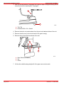
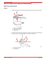
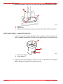
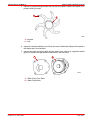
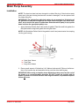
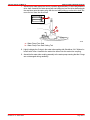
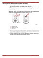
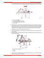
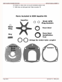
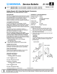
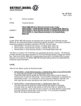
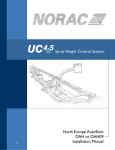
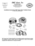
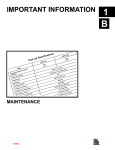
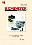
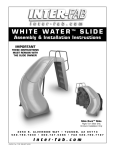
GEAR HOUSING STANDARD ROTATION
SERVICE MANUAL NUMBER 14
Drive Shaft Housing/Gear Housing
Separation
1. Clamp the unit on the gear housing anti-ventilation plate in a suitable fixture.
2. Tilt the unit at a 45 degree angle, remove the oil fill/drain plug, then remove the drive
shaft housing vent screw. Allow the drive unit to drain completely.
b
a
22101
22103
a - Fill/Drain Screw
b - Sealing Washer Or O-ring
b
a
70131
a - Vent Screw
b - Sealing Washer Or O-ring
90-818177--3 APRIL 2001
Page 3B-13
GEAR HOUSING STANDARD ROTATION
SERVICE MANUAL NUMBER 14
3. Mark the trim tab position (if equipped) with a piece of tape on the gear housing and remove the trim tab or anodic plate, if equipped.
b
a
70116
a - Trim Tab
b - Extension With 1/2 in. Socket
4. Remove the bolts, nuts and washers from the port and starboard sides of the unit.
5. Remove the aft screw (in the trim tab well of the gear housing).
6. Remove the nut from the forward end of the unit.
a
b
c
70117
a - Nuts, Bolts And Washers
b - Nut
c - Screw
7. Lift the drive shaft housing straight off of the gear case and set aside.
Page 3B-14
90-818177--3 APRIL 2001
GEAR HOUSING STANDARD ROTATION
SERVICE MANUAL NUMBER 14
Gear Housing and Component Disassembly
Water Pump Subassembly
REMOVAL
1. Remove the water seal, water tube coupling assembly and the water pump screws.
c
a
b
70486
a - Water Tube Assembly
b - Water Pump Screws
c - Water Seal
2. Carefully slide the water pump straight up off of the drive shaft. It may be necessary to
gently pry up on its mounting flanges with a couple of screwdrivers.
a
b
b
70487
a - Water Pump Body
b - Screwdrivers
90-818177--3 APRIL 2001
Page 3B-15
GEAR HOUSING STANDARD ROTATION
SERVICE MANUAL NUMBER 14
3. Remove the impeller, impeller key, the face plate and gaskets (discard the gaskets).
a
c
b
70605
a - Impeller
b - Impeller Key
c - Water Pump Face Plate and Gaskets (One On Each Side Of The Face Plate)
WATER PUMP ASSEMBLY - COMPONENT INSPECTION
1. Inspect the water tube coupling assembly for wear or damage. If necessary, replace the
worn or damaged components. Check the top and bottom inside O-ring seals for wear.
b
a
b
70613
a - Water Tube Adaptor
b - O-ring Seals (2)
2. Inspect the water pump impeller for wear on the end, top and bottom of the impeller
blades. Replace the impeller if this condition is found.
Page 3B-16
90-818177--3 APRIL 2001
GEAR HOUSING STANDARD ROTATION
SERVICE MANUAL NUMBER 14
3. Inspect for proper bonding between the hub and the impeller. Replace the impeller if improper bonding is found.
a
b
70500
a - Impeller
b - Hub
4. Inspect the impeller blades to see if they are hard or deformed. Replace the impeller if
the blades are in this condition.
5. Inspect the water pump face plate and the water pump interior for roughness and/or
grooves. Replace the appropriate components if any are found.
a
b
70609
a - Water Pump Face Plate
b - Water Pump Body
90-818177--3 APRIL 2001
Page 3B-17
GEAR HOUSING STANDARD ROTATION
SERVICE MANUAL NUMBER 14
Water Pump Assembly
Installation
NOTE: The aluminum dam has been changed to a rubber filler plug. If the aluminum water
pump dam in the gear housing has become corroded or damaged, it can be replaced with
the rubber filler plug.
IMPORTANT: The gaskets/face plate hole pattern is not symmetrical. If the holes of
the gaskets/face plate do not align with the screw holes of the gear case and/or each
other, one or more of the parts is upside down. Determine which part(s) is (are) upside
down and turn the appropriate part(s) over.
1. Apply Quicksilver Perfect Seal to the small hole gasket. Place the small hole gasket, the
face plate and the large hole gasket onto the gear case.
NOTE: Add Quicksilver Perfect Seal to the gasket to seal it and prevent water from seeping
into the gear housing.
c
b
a
70720
a - Small Hole Gasket
b - Face Plate
c - Large Hole Gasket
2. Place a small amount of Quicksilver 2-4-C Marine Lubricant with Teflon on the flat surface of the impeller key and assemble the key onto the drive shaft keyway.
IMPORTANT: When using an impeller whose blades have taken a set, face the curl of
the blades in a counterclockwise direction. DO NOT install the impeller with its
blades oriented in a reversed direction from original rotation, or premature impeller
failure will occur.
90-818177--3 APRIL 2001
Page 3B-75
GEAR HOUSING STANDARD ROTATION
SERVICE MANUAL NUMBER 14
3. Assemble the water pump impeller onto the drive shaft and down over the key.
a
b
70721
a - Water Pump Impeller
b - Water Pump Impeller Key
4. On early models, install the two (2) water pump locating pins through the gaskets and
face plate.
5. Position the water pump body over the drive shaft and water pump locating pins. Rotate
the drive shaft in a clockwise direction, while pushing down on the water pump body to
ease the water pump over the impeller blades.
b
a
70722
a - Water Pump Body
b - Water Pump Alignment Pins (91-821571A1)
c - Drive Shaft (Turn Clockwise While Installing Water Pump Body)
NOTE: Apply Quicksilver Perfect Seal to all four(4) screw threads before installation.
6. Hand start two (2) fasteners into the water pump assembly and remove the water pump
locating pins. Assemble the remaining two (2) fasteners. Run all fasteners down and
torque to 60 lb-in. (7.9 Nm).
IMPORTANT: The water pump face seal must be installed as outlined below. Improperly installing the water pump face seal may result in premature failure of the unit.
Page 3B-76
90-818177--3 APRIL 2001
GEAR HOUSING STANDARD ROTATION
SERVICE MANUAL NUMBER 14
7. Assemble the water pump face seal to a position approximately 1/2 of the way down the
drive shaft. Assemble the water pump face seal setting tool over the drive shaft and push
the seal down onto the water pump with the tool while pulling up on the drive shaft. Remove the tool from the drive shaft.
a
70504
b
a
70708
a - Water Pump Face Seal
b - Water Pump Face Seal Setting Tool
8. Lightly lubricate the O-rings in the water tube coupling with Quicksilver 2-4-C Marine Lubricant with Teflon. Assemble the water tube sleeve into the water tube coupling.
9. Assemble the water tube coupling assembly to the water pump ensuring that the O-rings
are not damaged during assembly.
90-818177--3 APRIL 2001
Page 3B-77
GEAR HOUSING STANDARD ROTATION
SERVICE MANUAL NUMBER 14
Joining Drive Shaft Housing/Gear Housing
1. Lubricate the end of the water tube (in the drive shaft housing) and the splines of the
drive shaft with Quicksilver 2-4-C Marine Lubricant with Teflon.
NOTE: The aluminum dam has been changed to a rubber filler plug. If the aluminum water
pump dam in the gear housing has become corroded or damaged, it can be replaced with
the rubber filler plug.
IMPORTANT: Ensure that the drain hole of the aluminum water pump dam is not
clogged with any foreign material as damage may occur if it is.
b
c
a
71410
71436
a - Aluminum Dam
b - Rubber Filler Plug
c - Drain Hole
2. Units with an aluminum dam installed in them will require a bead of Permatex Ultra Blue
Silicone Sealant along the top of the water pump dam as shown. If rubber filler plug is
present, it is not necessary to use this sealant.
3. To replace the aluminum dam if it has been removed and undamaged, place a bead of
Permatex Ultra Blue Silicone Sealant down both sides of it.
Page 3B-78
90-818177--3 APRIL 2001
GEAR HOUSING STANDARD ROTATION
SERVICE MANUAL NUMBER 14
4. Ensure that the water pump dam in the drive shaft housing is present and installed correctly. Ensure that all parts are present on the gear housing and the drive shaft housing.
a
c
b
d
70710
a
b
c
d
- Drive Shaft Splines
- Sealant - Aluminum Dam Only
- Trim Tab Bolt (Insert In Aft Hole)
- Quad Ring
5. Position the drive shaft housing straight above the gear housing. Align the water tube
sleeve with the water tube and the drive shaft with the upper drive gear and assemble
the drive shaft housing to the gear housing. It may be necessary to rotate the propeller
shaft or the u-joint to align the drive shaft splines with the upper drive gear splines.
6. Assemble the front nut to the front stud of the unit.
7. Assemble the aft screw and star washer (into the forward hole in the trim tab well of the
gear housing).
8. Assemble the bolts, nuts and washers to the port and starboard sides of the unit. Torque
to 35 lb.ft. (47.5 Nm).
a
b
c
70117
a - Nuts, Bolts, Washers
b - Nut
c - Screw
9. Assemble the trim tab and align it to the mark made previously on the gear housing.
Torque the screw to 23 lb-ft (31 Nm).
90-818177--3 APRIL 2001
Page 3B-79