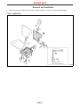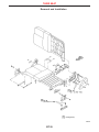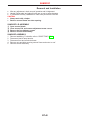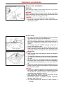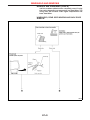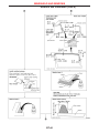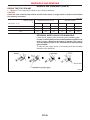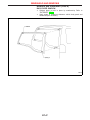
1
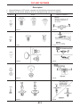
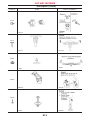
BODY & TRIM
SECTION
BT
CONTENTS
PRECAUTIONS ...............................................................2
Service Notice..............................................................2
Supplemental Restraint System (SRS) ″AIR
BAG″ and ″SEAT BELT PRE-TENSIONER″...............2
CLIP AND FASTENER ....................................................3
Description ...................................................................3
CHASSIS AND BODY MAINTENANCE .........................5
Checking Body Corrosion............................................5
BODY FRONT END.........................................................6
Removal and Installation .............................................6
BODY REAR END AND OPENER..................................8
Removal and Installation .............................................8
DOOR.............................................................................10
Removal and Installation ...........................................10
INSTRUMENT PANEL ASSEMBLY ..............................16
Removal and Installation ...........................................16
SIDE AND FLOOR TRIM ..............................................18
Removal and Installation ...........................................18
DOOR TRIM...................................................................19
Removal and Installation ...........................................19
ROOF TRIM ...................................................................20
Removal and Installation ...........................................20
EXTERIOR .....................................................................21
Removal and Installation ...........................................21
FRONT SEAT.................................................................34
Removal and Installation ...........................................34
Heated Seat...............................................................36
Active Head Restraint................................................36
SECOND SEAT..............................................................37
Removal and Installation ...........................................37
THIRD SEAT ..................................................................39
Removal and Installation ...........................................39
SUNROOF......................................................................40
Removal and Installation ...........................................40
WINDSHIELD AND WINDOWS ....................................42
Removal and Installation ...........................................42
DOOR MIRROR .............................................................48
Removal and Installation ...........................................48
BODY (ALIGNMENT) ....................................................49
Alignment ...................................................................49
PRECAUTIONS
Service Notice
I
I
I
I
I
When removing or installing various parts, place a cloth or padding onto the vehicle body to prevent
scratches.
Handle trim, molding, instruments, grille, etc. carefully during removing or installing. Be careful not to oil
or damage them.
Apply sealing compound where necessary when installing parts.
When applying sealing compound, be careful that the sealing compound does not protrude from parts.
When replacing any metal parts (for example body outer panel, members, etc.), be sure to take rust prevention measures.
Supplemental Restraint System (SRS) “AIR
BAG” and “SEAT BELT PRE-TENSIONER”
The Supplemental Restraint System such as “AIR BAG” and “SEAT BELT PRE-TENSIONER” used along with
a seat belt, helps to reduce the risk or severity of injury to the driver and front passenger for certain types of
collision. The SRS system composition which is available to NISSAN MODEL R20 is as follows (The composition varies according to the destination and optional equipment.):
I For a frontal collision
The Supplemental Restraint System consists of driver air bag module (located in the center of the steering wheel), front passenger air bag module (located on the instrument panel on passenger side), front seat
belt pre-tensioners, a diagnosis sensor unit, warning lamp, wiring harness and spiral cable.
I For a side collision
The Supplemental Restraint System consists of front side air bag module (located in the outer side of front
seat), side air bag (satellite) sensor, diagnosis sensor unit (one of components of air bags for a frontal
collision), wiring harness, warning lamp (one of components of air bags for a frontal collision).
Information necessary to service the system safely is included in the RS section of this Service Manual.
WARNING:
I To avoid rendering the SRS inoperative, which could increase the risk of personal injury or death
in the event of a collision which would result in air bag inflation, all maintenance should be performed by an authorized NISSAN dealer.
I Improper maintenance, including incorrect removal and installation of the SRS, can lead to personal injury caused by unintentional activation of the system. For removal of Spiral Cable and Air
Bag Module, see the RS section.
I Do not use electrical test equipment on any circuit related to the SRS unless instructed to in this
Service Manual. Spiral cable and wiring harnesses covered with yellow insulation tape either just
before the harness connectors or for the complete harness are related to the SRS.
BT-2
CLIP AND FASTENER
Description
I
I
Clips and fasteners in BT section correspond to the following numbers and symbols.
Replace any clips and/or fasteners which are damaged during removal or installation.
Symbol No.
Shapes
Removal & Installation
C101
SBF302H
SBF367BA
YBT081
SBF115B
SBF090B
SBF091B
SBF241B
SBF242B
SBF258G
SBF708E
C102
C106
C201
C203
BT-3
CLIP AND FASTENER
Description (Cont’d)
Symbol No.
Shapes
Removal & Installation
CG101
SBF145B
SBF085B
SBF174D
SBF175DA
YBT091
YBT092
SBF768B
SBF770B
YBT094
SBF992G
CE117
CE801
CR103
CS103
BT-4
CHASSIS AND BODY MAINTENANCE
Checking Body Corrosion
Visually check the body sheet metal panel for corrosion, paint damage (scratches, chipping, rubbing, etc.) or
damage to the anti-corrosion materials. In particular, check the following locations.
Hemmed portion
Hood front end, door lower end, back door rear end, etc.
Panel joint
Side sill of rear fender and center pillar, rear wheel housing of rear fender, around strut tower in engine
compartment, etc.
Panel edge
Back door opening, sunroof opening, fender wheelarch flange, fuel filler lid flange, around holes in panel, etc.
Parts contact
Waist molding, windshield molding, bumper, etc.
Protectors
Damage or condition of mudguard, fender protector, chipping protector, etc.
Anti-corrosion materials
Damage or separation of anti-corrosion materials under the body.
Drain holes
Condition of drain holes at door and side sill.
When repairing corroded areas, refer to the Corrosion Repair Manual.
BT-5
BODY FRONT END
Removal and Installation
I
I
I
I
I
When removing or installing hood, place a cloth or other padding on hood. This prevents vehicle body from
being scratched.
Bumper fascia is made of plastic. Do not use excessive force and be sure to keep oil away from it.
Hood adjustment: Adjust at hinge portion.
Hood lock adjustment: After adjusting, check hood lock control operation. Apply a coat of grease to hood
locks engaging mechanism.
Hood opener: Do not attempt to bend cable forcibly. Doing so increases effort required to unlock hood.
BT-6
BODY FRONT END
Removal and Installation (Cont’d)
FRONT BUMPER ASSEMBLY
YBT063
BT-7
BODY REAR END AND OPENER
Removal and Installation
I
I
I
I
I
When removing or installing back door, place a cloth or other padding on back door. This prevents vehicle
body from being scratched.
Bumper fascia is made of plastic. Do not use excessive force and be sure to keep oil away from it.
Back door adjustment: Adjust at hinge-back door portion for proper back door fit.
Back door lock system adjustment: Adjust striker so that it is in the center of the lock. After adjustment,
check back door lock operation.
After installation, make sure that back door and fuel filler lid open smoothly.
REAR BUMPER ASSEMBLY
NBF363
BT-8
BODY REAR END AND OPENER
Removal and Installation (Cont’d)
NBF364
BT-9
DOOR
Removal and Installation
FRONT DOOR
I
I
I
For removal of front door finisher, refer to “DOOR TRIM”,
BT-19.
Remove sealing screen.
After adjusting door or door lock, check door lock operation.
NBF226
BT-10
DOOR
Removal and Installation (Cont’d)
EBF003
BT-11
DOOR
Removal and Installation (Cont’d)
REAR DOOR
Wagon
I For removal of rear door finisher, refer to “DOOR TRIM”, BT-19.
I Remove sealing screen.
I After adjusting door or door lock, make sure door lock properly.
EBF004
BT-12
DOOR
Removal and Installation (Cont’d)
YBT086
BT-13
DOOR
Removal and Installation (Cont’d)
I
After adjusting door or door lock, make sure door locks properly.
BACK DOOR
NBF365
BT-14
DOOR
Removal and Installation (Cont’d)
NBF366
BT-15
INSTRUMENT PANEL ASSEMBLY
Removal and Installation
CAUTION:
I Disconnect ground terminal from battery in advance.
I Disconnect air bag system line in advance.
I Never tamper with or force air bag lid open, as this may adversely affect air bag performance.
I Be careful not to scratch pad and other parts.
BT-16
INSTRUMENT PANEL ASSEMBLY
Removal and Installation (Cont’d)
NBF367
BT-17
SIDE AND FLOOR TRIM
Removal and Installation
CAUTION:
I Wrap the tip of flat-bladed screwdriver with a cloth when removing metal clips from garnishes.
NBF368
BT-18
DOOR TRIM
Removal and Installation
CAUTION:
I When removing the outside mirror cover, situated at the inside of the door, pull the cover straight
out to prevent the fasteners from breaking.
EBF008
BT-19
ROOF TRIM
Removal and Installation
NBF229
BT-20
EXTERIOR
Removal and Installation
YBT064
BT-21
EXTERIOR
Removal and Installation (Cont’d)
YBT065
BT-22
EXTERIOR
Removal and Installation (Cont’d)
YBT066
BT-23
EXTERIOR
Removal and Installation (Cont’d)
YBT067
BT-24
EXTERIOR
Removal and Installation (Cont’d)
YBT068
BT-25
EXTERIOR
Removal and Installation (Cont’d)
YBT069
BT-26
EXTERIOR
Removal and Installation (Cont’d)
YBT070
BT-27
EXTERIOR
Removal and Installation (Cont’d)
YBT071
BT-28
EXTERIOR
Removal and Installation (Cont’d)
YBT072
BT-29
EXTERIOR
Removal and Installation (Cont’d)
YBT073
BT-30
EXTERIOR
Removal and Installation (Cont’d)
YBT076
BT-31
EXTERIOR
Removal and Installation (Cont’d)
YBT074
BT-32
EXTERIOR
Removal and Installation (Cont’d)
YBT075
BT-33
FRONT SEAT
Removal and Installation
I When removing or installing the seat trim, carefully handle it to keep dirt out and avoid damage.
CAUTION:
I Before removing the front seat, turn the ignition switch off, disconnect both battery cables and wait
at least 3 minutes (models with side air bag).
I Do not drop, tilt, or bump the side air bag module installed in the seat. Always handle it with care.
I Disconnect the side air bag harness connector and heated seat harness connector from under the
seat before removing the seat.
I Disconnect the side air bag harness connector before removing the seatback. Refer to RS-27,
“Front Side Air Bag Module” for details.
BT-34
FRONT SEAT
Removal and Installation (Cont’d)
NBT177
BT-35
FRONT SEAT
Heated Seat
★ For Wiring Diagram, refer to EL-128, “HEATED SEAT” for details.
Active Head Restraint
The active head restraint system is designed so that the headrest
instantaneously moves towards the front upper direction by utilizing the force at the seatback during a rear-end collision.
As a result, the occupant’s head is protected from being
overextended, reducing the chance for neck injury as much as
possible.
Seat with active head restraint have the labels shown in figures at
left.
SBT014A
OPERATION OUTLINE
When the seatback receives a sharp backward force during a rearend collision, the input plate moves with the link rotating center as
a pivot. The headrest will then move towards the front upper direction with the center of the sliding roller as a pivot.
As the backward force on the seatback is eliminated, spring tension
returns the headrest to its original position.
SBT888
BT-36
SECOND SEAT
Removal and Installation
I
When removing or installing the seat trim, handle carefully to keep dirt out and avoid damage.
TYPE 1 (HARDTOP)
EBF024
BT-37
SECOND SEAT
Removal and Installation (Cont’d)
TYPE 2 (WAGON)
EBF025
BT-38
THIRD SEAT
Removal and Installation
NBF236
BT-39
SUNROOF
Removal and Installation
I After any adjustment, check sunroof operation and lid alignment.
I Handle finisher plate and glass lid with care so not to cause damage.
I It is desirable for easy installation to mark each point before removal.
CAUTION:
I Always work with a helper.
I Remove sunroof frame rear door opening.
SUNROOF LID ASSEMBLY
q
1
q
2
q
3
q
4
Open sunroof shade.
Close sunroof lid, and remove adjustment screw covers.
Remove the four adjuster screws
Remove sunroof lid assembly.
SUNROOF ASSEMBLY
1.
2.
3.
4.
5.
Remove headlining. For details, refer to “ROOF TRIM”, BT-20.
Disconnect interior lamp harness.
Disconnect front and rear drain hoses.
Remove nuts and bolts securing sunroof frame and motor to roof.
Remove sunroof assembly.
BT-40
SUNROOF
Removal and Installation (Cont’d)
EBF032
BT-41
WINDSHIELD AND WINDOWS
Removal and Installation
REMOVAL
SBF034BA
After removing moldings, remove glass using piano wire or power
cutting tool and an inflatable pump bag.
WARNING:
When cutting the glass from the vehicle, always wear safety
glasses and heavy gloves to help prevent glass splinters from
entering your eyes or cutting your hands.
CAUTION:
I Be careful not to scratch the glass when removing.
I Do not set or stand the glass on its edge. Small chips may
develop into cracks.
INSTALLATION
I
SBT472
SBT473
Use a genuine Nissan Urethane Adhesive Kit or equivalent
and follow the instructions furnished with it.
I While the urethane adhesive is curing, open a door window. This will prevent the glass from being forced out by
passenger compartment air pressure when a door is
closed.
I The molding must be installed securely so that it is in
position and leaves no gap.
I Inform the customer that the vehicle should remain stationary until the urethane adhesive has completely cured
(preferably 24 hours). Curing time varies with temperature
and humidity.
WARNING:
I Keep heat and open flames away as primers and adhesive
are flammable.
I The materials contained in the kit are harmful if swallowed,
and may irritate skin and eyes. Avoid contact with the skin
and eyes.
I Use in an open, well ventilated location. Avoid breathing
the vapors. They can be harmful if inhaled. If affected by
vapor inhalation, immediately move to an area with fresh
air.
I Driving the vehicle before the urethane adhesive has completely cured may affect the performance of the windshield
in case of an accident.
CAUTION:
I Do not use an adhesive which is past its usable term. Shelf
life of this product is limited to six months after the date
of manufacture. Carefully adhere to the expiration or
manufacture date printed on the box.
I Keep primers and adhesive in a cool, dry place. Ideally,
they should be stored in a refrigerator.
I Do not leave primers or adhesive cartridge unattended
with their caps open or off.
I The vehicle should not be driven for at least 24 hours or
BT-42
WINDSHIELD AND WINDOWS
Removal and Installation (Cont’d)
until the urethane adhesive has completely cured. Curing
time varies depending on temperature and humidities. The
curing time will increase under higher temperatures and
lower humidities.
WINDSHIELD, REAR SIDE WINDOW AND BACK DOOR
WINDOW
YBT078
BT-43
WINDSHIELD AND WINDOWS
Removal and Installation (Cont’d)
YBT079
BT-44
WINDSHIELD AND WINDOWS
Removal and Installation (Cont’d)
YBT080
*1 BT-46
*2 BT-21
BT-45
WINDSHIELD AND WINDOWS
Removal and Installation (Cont’d)
DRYING TIME FOR SEALANT
I Reference: Time required for sealant to dry to desired hardness.
CAUTION:
Advise the user of the fact that vehicle should not be driven on rough roads or surfaces until sealant
has properly vulcanized.
Unit: days
Relative humidity
%
Temperature °C (°F)
40 (104)
Windshield and Rear window
Back door window
90
50
25
90
50
25
1.5
2.5
5.0
1.5
2.5
5.5
25 (77)
2.5
4.0
7.5
2.5
4.5
8.5
5 (41)
5.0
13.0
20.5
5.5
14.0
22.0
REPAIRING WATER LEAKS FOR WINDSHIELD
Leaks can be repaired without removing and reinstalling glass.
If water is leaking between the urethane adhesive material and
body or glass, determine the extent of leakage. This can be
done by applying water to the windshield area while pushing
glass outward.
To stop the leak, apply primer (if necessary) and then urethane
adhesive to the leak point.
SBF543B
BT-46
WINDSHIELD AND WINDOWS
Removal and Installation (Cont’d)
BACK DOOR WINDOW
I
I
Window glass is held in place by weatherstrip. Refer to
“EXTERIOR”, BT-21.
Apply sealer to clearances between vehicle body panel and
weatherstrip as necessary.
EBF030
BT-47
DOOR MIRROR
Removal and Installation
CAUTION:
Be careful not to scratch door rearview mirror body.
★ For Wiring Diagram, refer to EL-241, “DOOR MIRROR” for details.
1. Remove door trim. Refer to “DOOR TRIM”, BT-19.
2. Remove inner cover front corner of door.
3. Disconnect door mirror harness connector.
4. Remove harness clips.
5. Remove bolts securing door mirror assembly.
EBF031
BT-48
BODY (ALIGNMENT)
Alignment
I
I
I
I
I
I
All dimensions indicated in figures are actual ones.
When using a tracking gauge, adjust both pointers to equal length. Then check the pointers and gauge
itself to make sure there is no free play.
When a measuring tape is used, check to be sure there is no elongation, twisting or bending.
Measurements should be taken at the center of the mounting holes.
An asterisk (*) following the value at the measuring point indicates that the measuring point on the other
side is symmetrically the same value.
The coordinates of the measurement points are the distances measured from the standard line of “X”, “Y”
and “Z”.
YBT089
BT-49
BODY (ALIGNMENT)
Alignment (Cont’d)
ENGINE COMPARTMENT
Measurement
Unit: mm (in)
NBF021
BT-50
BODY (ALIGNMENT)
Alignment (Cont’d)
Detailed Measurement Points
Points
q
A
Coordinates mm (in)
Hole dia.
mm (in)
Detailed points
8 (0.32)
“X”
“Y”
“Z”
Cowl top hole at
vehicle center
0.0
(0.00)
250.0
(9.84)
760.9
(29.96)
Cowl top side
hole
698.5
(27.50)
−110.1
(−4.34)
624.7
(24.59)
NBF022
q
B q
b
11 (0.43)
NBF023
q
D q
d
8 (0.32)
Upper radiator
core support
location hole
691.0
(27.20)
−459.5
(−18.09)
548.0
(21.58)
q
H q
h
16 (0.63)
Side radiator
core support
location hole
680.0
(26.77)
−551.7
(−21.72)
400.0
(15.75)
NBF024
q
1 : Coordinate indicated is LH , RH coordinate is - LH coordinate.
E.g. if LH coordinate is: 698.5, RH coordinate is: −698.5.
BT-51
BODY (ALIGNMENT)
Alignment (Cont’d)
Points
q
E
Coordinates mm (in)
Hole dia.
mm (in)
Detailed points
9 (0.35)
q
I
q
G q
g
12 (0.47)
NBF025
q
C q
c
7.2 (0.28)
NBF027
q
1 : Coordinate indicated is LH , RH
E.g. if LH coordinate is: 698.5,
coordinate is - LH coordinate.
coordinate is: −698.5.
RH
BT-52
“X”
“Y”
“Z”
Hood lock stay
mounting hole
on upper radiator core support
37.0
(1.46)
−589.0
(−23.19)
494.0
(19.45)
Lower radiator
core support
mounting hole
0.0
(0.00)
−581.1
(−22.88)
−54.1
(−2.13)
Lower radiator
core support
location hole
280.0
(11.02)
−608.9
(−23.97)
−23.0
(−0.91)
Front fender
mounting hole
on hoodledge
698.5
(27.50)
−110.1
(−4.34)
624.7
(24.59)
BODY (ALIGNMENT)
Alignment (Cont’d)
UNDERBODY
Measurement (Hardtop model)
NBF028
BT-53
BODY (ALIGNMENT)
Alignment (Cont’d)
NBF029
BT-54
BODY (ALIGNMENT)
Alignment (Cont’d)
UNDERBODY
Measurement (Wagon model)
NBF030
BT-55
BODY (ALIGNMENT)
Alignment (Cont’d)
NBF031
BT-56
BODY (ALIGNMENT)
Alignment (Cont’d)
Detailed Measurement Points
Coordinates mm (in)
Points
Detailed points
“X”
“Y”
“Z”
q
A q
a
450.0
(17.72)
−488.5
(−19.23)
58.0
(2.28)
D q
d
q
605.0
(23.82)
597.5
(23.52)
4.7
(0.18)
q
E q
e
593.5
(23.37)
1,537.0
(60.51)
10.0
(0.39)
W :
600.0
(23.62)
W :
2,135.0
(84.06)
W :
140.2
(5.52)
593.5
(23.37)
W :
3,477.5
(136.91)
H :
2,997.5
(118.01)
195.5
(7.70)
Front shock
absorber bracket
mounting hole
442.0
(17.40)
−16.0
(−0.63)
196.5
(7.74)
Compression rod
mounting hole
362.6
(14.28)
290.0
(11.42)
−158.9
(−6.26)
Body mounting
bracket hole
q
G q
g
q
K q
k
SBF274B
q
B q
b
NBF032
q
C q
c
NBF033
q
1 : Coordinate indicated is LH , RH
E.g. if LH coordinate is: 698.5,
coordinate is - LH coordinate.
coordinate is: −698.5.
RH
BT-57
BODY (ALIGNMENT)
Alignment (Cont’d)
Coordinates mm (in)
Points
Detailed points
Lower link mounting bracket hole
q
F q
f
“X”
“Y”
“Z”
538.0
(21.18)
W :
2,059.0
(81.06)
H :
1,859.0
(73.19)
−146.0
(−5.75)
270.7
(10.66)
W :
2,382.3
(93.79)
H :
2,182.3
(85.92)
5.0
(0.20)
375.0
(14.76)
W :
2,610.0
(102.76)
H :
2,410.0
(94.88)
210.0
(8.27)
W :
2,843.7
(111.96)
H :
2,643.7
(104.08)
−55.0
(−2.16)
NBF034
Upper link mounting bracket hole
q
H q
h
NBF035
Rear spring
mounting bracket
hole
q
I q
i
NBF036
Rear panhard rod
mounting bracket
hole
q
j
NBF037
q
1 : Coordinate indicated is LH , RH
E.g. if LH coordinate is: 698.5,
coordinate is - LH coordinate.
coordinate is: −698.5.
RH
BT-58
RH
only
−495.8
(−19.52)
BODY (ALIGNMENT)
Alignment (Cont’d)
Coordinates mm (in)
Points
Detailed points
5th crossmember
location hole
q
L q
l
6th crossmember
location hole
q
M q
m
NBF038
q
1 : Coordinate indicated is LH , RH
E.g. if LH coordinate is: 698.5,
coordinate is - LH coordinate.
coordinate is: −698.5.
RH
BT-59
“X”
“Y”
“Z”
225.0
(8.86)
W :
2,961.0
(116.58)
H :
2,637.0
(103.82)
W :
264.4
(10.41)
H :
284.4
(11.20)
300.0
(11.81)
W :
3,530.0
(138.98)
H :
3,050.0
(120.08)
240.6
(9.47)
NOTES