1
TABLE SAW
ModeJ No.
137o228210
CAUTmON:
,,
,,
o
•
Before using this Table Saw,
read this manual and follow all its
Safety Rules and Operating
Instructions.
Customer
He_p
Safety Instructions
installation
Operation
Maintenance
Parts List
Line
t =800-843-t682
Sears,
Roebuck
and Co., Hoffman
Part No. 137228210001
Estates,
IL 60179
USA
SECTION
PAGE
Warranty ....................................................................
Product Specifications
........................................................
Safety Instructions
...........................................................
Accessories
and Attachments
..................................................
Tools Needed ................................................................
Carton Contents
.............................................................
Know your Table Saw .........................................................
Glossary
of Terms ............................................................
Assembly
and Adjustments
...................................................
Operation
..................................................................
Maintenance
................................................................
Troubleshootin_Guide
.......................................................
Making a Push atick
.........................................................
Parts ......................................................................
2
2
3
{_
6
6
8
9
10
17
21
22
23
24
k_
GENERAL SAFETY INSTRUCTIONS
BEFORE
READ and become familiar with this entire instruction
manual. LEARN the tool's applications, limitations, and
possible hazards.
1.
.
FULL ONE YEAR WARRANTY
If this product fails due to a defect in material or workmanship within one year from the date of purchase, Sears
will repair it free of charge.
.
Contact a Sears Service Center for repair,
,
or rental purposes, this warranty applies only for 90 days from the date of
7.
This warranty gives you specific legal rights, and you may also have other rights which vary from state to state.
Estates, iL 60179
,
.
MOTOR
Maximum developed HP .............
Volts ............................
Amperes ....................
Hertz ............................
RPM (no load) .....................
Overload protection .................
: ....
2
120
8.5
60
3450
YES
SAW
Table Wi Extension wing .............
Blade ............................
Max. depth of cut at 90 ° . .............
Max. depth of cut at 45 ° . .............
Max. width of dado ..................
Weight ...........................
40-1/4" x 27"
10" diameter
2-1/2"
2-1/4"
9/16"
40 Ibs.
Leg stand ........................
Miter Gauge .......................
Rip Fence . .. ; ....................
YES
YES
YES
To avoid electrical hazards, fire hazards, or damage to the
tool, use proper circuit protection.
Your table saw is wired at the factory for 120V operation.
Connect to a I20V, 15 AMP branch circuit and use a 15
AMP time delay fuse or circuit breaker. To avoid shock or
fire, replace power cord immediately if it is worn, cut or
damaged in any way.
SAW
To avoid mistakes that could cause serious injury, do not
plug the table saw in until you have read and understood the
following:
3.
Sears, Roebuck and Co., Dept. 817 WA, Hoffman
THE TABLE
Safety is a combination of common sense, staying alert and
knowing how to use your table saw.
,
If this product is used for commercial
purchase.
USING
12.
WEARYOUR
ALWAYS WEAR EYE
PROTECTION. Any table
saw can throw foreign
objects into the eyes which
could cause permanent eye
damage. ALWAYS wear
Safety Goggles (not glasses)
that comply with ANSI safety standard Z87.1.
Everyday eyeglasses have only impact-resistant
lenses. They ARE NOT safety glasses. Safety
GoggJes are available at Sears. NOTE: Glasses or
goggles not in compliance with ANSI Z87.1 could
seriously hurt you when they break.
13. WEAR A FACE MASK OR DUST MASK,
Sawing operation produces dust.
KEEP GUARDS IN PLACE and in working order.
!4. SECURE WORK. Use clamps or a vise to hold work
when practical, tt's safer than using your hand and it
frees both hands to operate too!.
REMOVE ADJUSTING KEYS AND WRENCHES.
Form the habit of checking to see that keys and
adjusting wrenches are removed from the tool before
turning ON.
15. DISCONNECTTOOLS before servicing, and when
changing accessories, such as blades, bits, cutters,
and the like.
KEEP WORK AREA CLEAN. Cluttered areas and
benches invite accidents.
16. REDUCE THE RISK OF UNtNTENTmONALSTARTING.
Make sure the switch is in OFF position before
plugging in.
DON'T USE iN A DANGEROUS ENVIRONMENT.
Don't use power tools in damp or wet locations, or
expose them to rain. Keep work area well lighted.
17_ USE RECOMMENDED ACCESSORIES. Consult the
owner's manual for the recommended accessories.
The use of improper accessories may cause risk of
injury to persons.
KEEP CHILDREN AWAY. All visitors should be kept at
a safe distance from the work area.
MAKE WORKSHOP KID PROOF with padlocks, master
switches, or by removing starter keys.
t8. NEVER STAND ON TOOL. Serious injury could occur
if the tool is tipped or if the cutting tool is unintentionally
contacted.
DON'T FORCE THE TOOL. It will do the job better
and safer at the rate for which it was designed.
19. CHECK FOR DAMAGED PARTS. Before further use of
the toot, a guard or other part that is damaged should
be carefully checked to determine that it will operate
properly and perform its intended function. Check for
alignment of moving parts, binding of moving parts,
breakage of parts, mounting, and any other conditions
that may affect its operation. A guard or other part that
is damaged should be properly repaired or replaced.
USE THE RIGHT TOOL. Don't force tool or the
attachment to do a job for which it was not designed.
10. USE PROPER EXTENSION CORD, Make sure your
extension cord is in good condition. When using an
extension cord, be sure to use one heavy enough to
carry the current your product will draw. An undersized
cord wil! cause a drop in line voltage resulting in loss
of power and overheating. The table on page 7 shows
the correct size to use depending on cord length and
nameplate ampere rating. If in doubt, use the next
heavier gauge. The smaller the gauge number, the
heavier the cord.
20. NEVER LEAVE TOOL RUNNING UNATTENDED.
TURN THE POWER OFF. Don't leave the tool until
it comes to a complete stop.
DON'T OVERREACH, Keep proper footing and
balance at all times.
11. WEAR PROPER APPAREL. DO NOT wear loose
clothing, gloves, neckties, rings, bracelets, or other
jewelry which may get caught in moving parts.
Nonslip footwear is recommended. Wear protective
hair covering to contain long hair.
MAINTAIN TOOLS WITH CARE. Keep tools sharp
and clean for best and safest performance. Follow
instructions for lubricating aqd changing accessories.
SAVE THESE INSTRUCTIONS
2
3
"\
24. WARNING: Dust generated from certain materials can
be injurious to your heal[h. Always operate saw in welt
ventilated areas and provide for proper dust removal.
SPEC RC SAFETY mNSTRUCTmONS
FOR THE TABLE SAW
,
2.
.
.
14. AVOID AWKWARD OPERATIONS and hand positions
where a sudden slip could cause your hand to move
into the cutting tool.
ALWAYS USE SAW BLADE GUARD spreader and
anti-kickback pawls for every operation for which
they can be used, including through-sawing.
Through-sawing operations are those in which the
blade cuts completely through the workpiece
when ripping or cross-cutting.
16. MOUNT your table saw before performing any cutting
operations. Refer to installation instructions.
USE A PUSH STICK when required. Always use a
push stick for ripping narrow stock. Refer to ripping
applications in the instruction manual where the
push stick is covered in detail. See the push stick
pattern included in this Owner's Manual.
17. NEVER CUT METALS or materials which may make
hazardous dust.
NEVER PERFORM ANY OPERATION
"FREE HAND", which means using only your hands
to support or guide the workpiece. Always use either
the fence or the miter gauge to position and guide the
work.
,]
iMPROPER CONNECTION of the equipment grounding
conductor can result in risk of electric shock. The
conductor with the green insulation (with or without yellow
stripes) is the equipment grounding conductor. If repair
or replacement of the etectric cord or plug is necessary,
DO NOT connect the equipment grounding conductor
to a live terminal.
USE 'ONLY 3-wire extension cords that have 3_prong
grounding plugs and 3-pole receptacles that accept
the tool's plug. Repair or replace damaged or worn
cord immediately.
6.
NEVER REACH behind or over the cutting tool
for any reason.
7.
REMOVE the rip fence when cross-cutting.
ELECTRmCAL REQUIREMENTS
8.
DO NOT USE molding head set with this saw.
POWER SUPPLY AND MOTOR SPEC_F]CATaONS
9.
FEED WORK INTO THE BLADE against the
direction of rotation only.
To avoid electrical hazards, fire hazards, or damage to the
tool, use proper circuit protection. Use a separate electrica!
circuit for your tools.Your saw is wired at the factory for t20V
operation. Connect to a 120V, 15 Amp circuit and use a 15
Amp time delay fuse or circuit breaker. To avoid shock or fire,
if power cord is worn or cut, or damaged in any way, have it
replaced immediately.
Grounding Prong
Properly Grounded
3-Prong Receptacle
Fig. B
Grounding Lug _-_
Make Sure This
is Connected to a
Known Ground
DO NOT MODIFY THE PLUG PROVIDED. If it will not fit
the receptacle, have the proper receptacle installed by a
qualified electrician.
19, NEVER LEAVE THE TOOL running unattended.
Don't leave the tool until it comes to a complete stop.
20. For proper operation follow the instructions of this
owner's manual titled *'SAW MOUNTED TO WORK
SURFACES." Failure to provide sawdust fall4hrough
and removal hole will allow sawdust to build up in the
motor area, which may result in a fire hazard or cause
motor damage.
11. NEVER ATTEMPTTO FREE A STALLED SAW
BLADE without first turning the saw OFR Turn
power switch OFF immediately to prevent motor
damage.
IN THE EVENT OF A MALFUNCTmON OR BREAKDOWN,
grounding provides a path of least resistance for electric
current and reduces the risk of electric shock. This tool is
equipped with an electric cord that has an equipment
grounding conductor and a grounding plug. The plug
MUST be plugged into a matching receptacle that is
properly installed and grounded in accordance with ALL
local codes and ordinances.
CHECK with a qualified electrician or service person if you
do not completely understand the grounding instructions, or if
you are not sure the tool is properly grounded.
NEVER STAND or have any part of your body in line
with the path of the saw blade. Keep your hands out
of the line of the saw blade.
3-Prong Plug
This tool must be grounded while in use to protect the
operator from electrical shock.
18. ALWAYS USE IN A WELL VENTILATED AREA.
Remove saw dust frequently. Clean out sawdust from
the interior of the saw to prevent a potential fire hazard.
5.
I0. NEVER use the fence as a cut-off gauge when
cross-cutting.
INSTRUCTIONS
Fig. A
]
!5. NEVER USE SOLVENTS to clean plastic parts.
Solvents could possibly dissolve or otherwise damage
the material. Only a soft damp cloth should be used to
clean plastic parts.
ALWAYS HOLDTHE WORK FIRMLY against the
miter gauge or rip fence.
Use a separate electrical circuit for your tools. This circuit
must not be less than #12 wire and should be protected
with a 15 Amp time tag fuse. Before connecting the motor
to the power line, make sure the switch is in the OFF
position and the electric current is rated the same as the
current stamped on the motor nameplate. Running at a
lower voltage will damage the motor.
This tool is intended for use on a circuit that has a receptacle
like the one illustrated in FIGURE A. FIGURE A shows a
3-prong electrical plug and receptacle that has a grounding
conductor. If a properly grounded receptacle is not available,
an adapter (FIGURE B) can be used to temporarily connect
this plug to a 2-contact ungrounded receptacle. The adapter
(FIGURE B) has a rigid lug extending from it that MUST be
connected to a permanent earth ground, such as a properly
grounded receptacle box. THE TEMPORARY ADAPTER
SHOULD BE USED ONLY UNTIL A PROPERLY
GROUNDED OUTLET CAN BE INSTALLED BY A
QUALIFIED ELECTRICBAN. The Canadian Electrical Code
prohibits the use of adapters.
2*Prong
Receptacle
This table saw is for indoor use only. Do not expose to rain
or use in damp locations
GUIDELINES
FOR
EXTENSION
!NSTRUCTMONS
4
CORDS
USE PROPER EXTENSION CORD. Make sure your
extension cord ts in good condition. When using an extension
cord, be sure to use one heavy enough to carry the current
your product will draw. An undersized cord witl result in a
drop in line voltage!and in loss of power which will cause the
tool to overheat. The tabIe below shows the correct size to
use depending on cord length and nameplate ampere rating.
If in doubt, use the next heavier gauge. The smaller the
gauge number, the heavier the cord.
Be sure your extension cord is properly wired and in
good condition. Always replace a damaged extension cord or
have it repaired by a qualified person before using it. Protect
your extension cords from sharp objects, excessive heat and
damp or wet areas.
(when
Ampere
more
1ban
Rating
not
more
th_n
using
Total
25'
120 volts
only)
!,e,n,,gth of cord
in feet
50'
100'
150'
o
6
18
16
16
14
6
10
18
16
14
12
10
12
16
16
14
12
16
14
12
Not
CAUT!ON: In a!! cases, make certain the receptac!e is
properly grounded. If you are not sure have a qualified
electrician check the receptacle.
12. PROVIDE ADEQUATE SUPPORT to the rear and
sides of the saw table for wide or long workpieces.
SAVE THESE
GROUNDING
13. AVOID KICKBACKS (work thrown back towards you)
by keeping the blade sharp, keeping the rip fence
parallel to the saw blade, and by keeping the spreader,
anti-kickback pawls, and guard in place
and functioning. Do not release work before it is
pushed all the way past the saw blade. Do not rip
work that is twisted, warped, or does not have a
straight edge to guide along the fence.
23. DIRECTmON OF FEED. Feed work into a blade or cutter
against the direction of rotation of the blade or cutter
only.
SAVE THESE mNSTRUCT ONS
12
Recommended
NOTE: To make assembly easier, keep the contents of the
box together. Apply a coat of automobile wax to the table.
Wipe all parts thoroughly with a clean dry cloth. This will
reduce friction when pushing the workpiece.
RECOMMENDED
ACCESSORIES
Visit your Sears Hardware Department or see the Craftsman
Power and Hand tools Catalog to purchase recommended
accessories for this power toot.
To avoid the risk of personal injury, do not modify this power
tool or use accessories net recommended by Sears.
Do not use adjustable (wobble) type dadoes or carbide
tipped dado blades on this saw. Maximum dado width is i/2".
Do not use a dado with a diameter larger than 6". Also do
not use molding head set with this saw.
Do not use any accessory unless you have completely read
the instruction or owner's rnanual for that accessory.
TOOLS
NEEDED
Medium screwdriver
Adjustable wrench
TABLE
ITEM
A
B
C
D
E
F
G
I I ili
II
Straight edge
i I !
Combination square
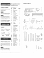
UNPACKING AND CHECKING CONTENTS
Separate all parts from packing material. Check each one
with the illustration and the list of loose parts to make certain
all items are a_ccountedfor, before discarding any packing
material,
PARTS
DESCRIPTION
Table
Btade guard and splitter
Rip fence
Rip fence handle
Miter gauge
Miter gauge handle
Table extension
QUANTITY
t
I
1
1
1
1
!
1
J
K
L
M
(Table extension hardware):
Hex. socket head
cap bolt M8x1.25-25
Flat washer 8.4x24-2
Hex. nut M8x1.25 T=5
Table extension set plates
Hex key
Blade wrenches
10
4
2
1
2
N
O
(Handwheel hardware):
Crown nuts
Handwheels
2
2
P
Q
R
S
T
U
V
W
X
(Splitter bracket hardware):
Hex hd. bolt M6x10-16
Flat washer 1/4x3/4-3/64
Tooth washer 6
Hex nut Mdxl.0 T=5
Hex hd. bolt M8x1.25-50
Tooth washer 8
Flat washer 5/16x7/8_5/64
Guard bracket
Self-locking ring
2
2
2
2
1
2
2
1
1
(Leg Stand):
Bracket
Bottom bracket (short)
Upper bracket (tong)
Upper bracket (short)
Bottom bracket (long)
4
2
2
2
2
H
#2 Phillips screwdriver
ii
OF LOOSE
Y
Z
AA
AB
AC
UNPACKING YOUR TABLE SAW
A
q
E
F
H
I
J
K
®
©©
N
M
-=
G
0
P
Q
R
S
T
U
V
W
Ti
!
@@¢__
o
AE
i3
_==@ (p==_=
AD
AE
AF
AG
(Leg stand hardware):
Cap head square neck bolt
Flat washer 3/8x29/32-5/64
Hex. nut M8x1.25 T=6.5
Spring washers
2O
2O
2O
16
AH
AI
AJ
AK
(Leg pad hardware):
Leg pads
Hex. hd. bolt M10x1.5-20
Hex. nut M10xl.5 T=8
Flat washer 10x20-2
4
4
4
4
I
.
i
J_
Z
Y
AA
AB
AC
AD
AF
%%%®
@_s,@
If any parts are missing, do not attempt to assemble the
table saw, plug in the power cord, or turn the switch on until
the missing parts are obtained and are installed correctly.
AG
6 ::::::::::::::::::::::::::::::::::::::::::::::::::::::::::::::::::::::::::::::::::::::::::::::::::::::::::::::::::::::::::::::::::::::::::::::::::::::::::::::::::::::::::::::::::::::::::::::::::::::::::::::::::::::::::
•
,{:
AH
AI
AJ
AK
X
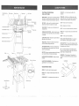
Blade Guard
Table(Left)
Extensi°n-x?
Table Insert
Rip Fence
re Gau,
Table Extension
(Right)
_9
Overload Resei Switch
On/Off
Switch
0¢
_
-Bevel Scale
Blade
Bevel Lock Handle
z
CROSSCUT-A
workpiece.
cut made across the width of the
MITER GAUGE -A guide used For"crosscutting operations
that slides in the table top channels located on either side
of the blade. It helps make accurate straight or angle cuts.
FREEHAND - Performing a cut without using a fence
(guide), hold down or other proper device to prevent the
workpiece from twisting during the cutting operation.
RIP FENCE -A guide used for rip cutting that clamps to
the table top. It allows the workpiece to be straight.
GUltfd-A
sticky sap from wood proclucts.
HEEL - Misaiignment of the blade.
wilh Key
Blade
Z
CRAFTS_AN
PROFESSHONAL
TABLE SAW TERMS
Blade Tilting
Handwheel
Table Scale
TABLE INSERT - Provides access to the blade arbor for
changing blades.
KERF o-o
The amount of material removed by a blade cut.
_/HTER CUT ._An angle cut made across the width el: the
workpiece.
OVERLOAD RESET SWITCH - Resets the thermocouple
and provides a way to restart the saw motor if it overheats
or overloads.
RESIN - A sticky sap that has hardened.
Blade
Elevation
BLADE BEVEL SCALE - Measures the angle the blade is
tilted when set for a bevel cut.
Handwheei
REVOLUTIONS PER M_NUTE (RPM) - The number of
turns completed by a spinning object in one minute.
TABLE SCALE - Measures the distance the rip fence is
set from the blade, allowing quick setups.
ANTI:KICKBACK
PAWLS - Prevents the workpiece from
being kicked upward or back toward the front of the table
saw by the spinning blade.
Leg Stand
Table
Blade
Anti-Kickback
SET -The distance between two saw blade tips, bent
outward in opposite directions to each other. The further
apart the tips are, the greater the set.
SPUTTER - Keeps the workpiece spread apart after being
cut, to prevent binding on the blade and workpiece.
Pawls
Splitter
BLADE ELEVATION HANDWHEEL
the blade.
Power
SAW BLADE PATH - The area of the workpiece or table
top directly in line with the travel of the blade or the part of
the workpiece which will be cut.
Cord Bracket
-Raises
WORKPIECE - The item being cut. The surfaces of a
workpiece are commonly referred to as faces, ends, and
edges.
and lowers
LeadingEdge
BLADE TILTING HANDWHEEL - Tilts the blade to any
angle between 0° to 45" for bevel cuts.
SawbladePath
Kerr
WOODWORKMNG
ARBOR -The
TERMS
Sudace
shaft on which a blade is mounted.
BEVEL CUT - An angle cut made through the face of the
workpiece.
\
Blade Wrenches
COMPOUND
Workpiece
CUT - A simultaneous bevel and miter cut.
Trailing Edge
Splitter Bracket
:
:
:
8
!:!-::/::!:::ii:::
¸::::
?::::::-
:_,:::/!::::/
:::::
_)L:::
/
:
/
: :
9
:
:
:
•
•
•
: : ••: • /•:vi•i
:/:•:•/::
::• /::i•::::i/:?::::::!:
¸
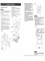
ASSEMBLY nNSTRUCTtONS
SAW TO LEG SET (FIG. B)
1. Before mounting the rip fence, blade guard, and miter
gauge to the saw top, invert the saw table so that it is
facing the floor.
2. Position the leg set upside down on the saw base.
3. Match the holes of the stand to the holes on the
bottom of the saw base.
4. Secure the leg set to the saw base using bolts,
washers, and nuts.
5. When all bolts and nuts are tightened, carefully place the
saw in its upright position.
6. Position the saw on a clean, level surface.
For your own safety, never connect plug to power source
ou[let until all assembly steps are complete, and you have
read and understood the safety and operating instructions.
LEG SET (FIG.A)
1. Separate all parts and group by size and style.
NOTE: Finger tighten bolts and nuts when joining
parts.
2.
3.
4.
5.
6.
7.
8.
9.
Fig. B
Use square neck bolts (1), washers (2), and nuts (3) to
assemble the leg set parts.
Attach a leg (4) to the long top bracket (5). Attach the
next leg to the opposite end of the top bracket. Do not
tighten.
Repeat this assembly for the opposite side of the
leg set. Do not tighten.
Attach the completed leg set assemblies to the short
top brackets (6). Repeat on the opposite side. Do not
tighten.
Insert bolt (7) into the recessed hole pad (8).
Insert into the leg flange hole and tighten, using
washer (9) and nut (10). Repeat for the three other legs.
Attach bottom brackets (11) between each leg.
Place the leg set on a level surface and tighten all
nuts and bolts.
Leg
mounting
hole
Fig.A
SAW MOUNTED TO OTHER SURFACES (FIG. D)
1. if the leg set will not be used, the saw must be
properly secured to a sturdy workbench using the four
mounting holes at the base of the saw.
2. A hole must be provided in the surface of the
workbench where the saw is mounted to facilitate
sawdust fall-through and removal.
3. Square the saw on the mounting surface and mark the
location of the four corners of the base.
4. Mark an 11 "x t3" rectangle centered between the'four
corners.
5. Cut out and remove the rectangle. This opening will
allow sawdust to fail through the saw base.
6. Place the table saw on the mounting surface, lining up
with the corner marks, and mark the location of the
table saw mounting holes.
7. Remove the table saw. The mounting hole marks
should form the corners bf a 14" by 16" rectangle.
8. Drill 3/8" holes into the mounting surface at the marks.
9. Place the saw on the surface, aligning the mounting
holes of the sawto the holes drilled in the mounting
surface. Fasten the saw to the surface with 3/8" bolts,
washers, and nuts.
Fig, D
1
2
o
Failure to provide the sawdust fatl4hrough and removal hole
will cause sawdust to build up in the motor area, which may
result in a fire hazard or cause motor damage, or injury.
KEEPING THE AREA CLEAN (FIG. E)
1. Saw dust and wood chips that fall from under the saw
will accumulate on the floor.
2. Make it a practice to pick up and discard this saw dust
when you have completed cutting.
3. Always keep your work area clean, uncluttered and well
lit. Do not work on floor surfaces that are slippery from
sawdust or wax.
Fig. E
\
Saw base
hole
11
To avoid injury always keep your work area clean, uncluttered
and well lit. Do not work on floor surfaces that are slippery
from sawdust or wax.
10:
•
' ....
:
,
_:
.....
: : ::
:i::: i: :':i ¸¸
:'
TABLE EXTENSION - LEFT SiDE (FIG. F, G)
1. Place a set plate bracket (1) in the corner of the table
extension (2), on the side to be attached to the table
saw,
2.
3.
4.
5.
Place washers (3) on two socket head cap bolts (4).
insert the bolts into the _ension
side, through the plate
bracket.
Place washers (5) and hex nuts (6) on the bolts; do not
tighten.
Repeat for the other set plate bracket. Do not tighten.
Fig. F
t
5
3
4
BLADE HANDWHEELS
(FIG. H, I)
MITER GAUGE (FIG. J)
1. Thread the miter gauge handle (1) into the top of the
miter gauge (2).
2. Loosen when changing miter angles, tighten when
locking at a chosen angle.
Blade raising handwheel (FIG. H)
1. Place a handwheel (1) on the elevation bolt (2). Make
sure the slots (3) in the hub of the handwheel engage
with the pins (4) on the bolt.
2. Attach and tighten the crown nut (6) to the end of the
shaft.
3.
4.
Fig. J
5.
2
Fig. H
Raise the blade (4) to the highest position by turning the
blade raising hand wheel counterclockwise. (F_G. M)
Using the two blade wrenches, place the open-end
wrench (5) on the flats of the saw arbor (6) to hold it
stationary, and the box-end wrench (7) on the saw arbor
nut (8).
Turn the box-end wrench counterclockwise to loosen the
arbor nut.
Fig.
w
1
2
7
2
Place the table extension next to the saw table, aligning
the mounting holes (7). (FIG. G)
7. Place washers (8) on two socket head cap bolts (9),. and
thread in the mounting holes.
8. Turn the table upright and place a straight edge or
combination square on the saw able, across the table
extension.
9. Adjust the mounting bolts (9) untiI the extension is flush
with the saw table. Tighten.
10. Adjust the extension to be level with the saw table, and
tighten the side bracket bolts (4).
4
r-"
6.
8
RiP FENCE (FIG. K)
1. Thread the fence handle (t) into the cam hole (2) and
tighten.
2. Lift upward on the rip fence handle so that the holding
clamp (3) is futly extended.
3. Place the rear of the rip fence on the back of the saw
table and engage the holding clamp to the table. Lower
the front end onto the front rail (4).
4. Push down on the fence handle to lock.
6.
Remove the arbor nut (8) and the outer btade flange (9).
Remove the blade (4). (FIG. N)
7. Place the new blade on the arbor, making sure the teeth
are pointing forward and down to the front of the saw
table.
[
8. Holding the blade flush against the inner blade
flange (10), place the outer blade flange (9) on the arbor
and against the blade.
9. Thread the arbor nut (8) onto the arbor as far as possible
by hand.
!0. Make sure that both flanges are flush against the blade.
Fig. K
6
i
3
t
Blade tiltit!g handwheei (FIG. i)
t. Attach the other handwheel (7) to the blade tilting bolt (8)
on the side of the table saw, in same manner as above.
2. Place the crown nut (10) on the bolt shaft and tighten.
Fig. N
Fig. G
2
--1
To avoid injury from an accidental start, make sure the switch
is in the OFF position and the plug is not connected to the
power source.
CHANGING THE BLADE (FIG. L, M, N)
1. Loosen and remove the table insert screw (t) with a
Phillips screwdriver. DO NOT loosen or remove the rear
insert screw (2).
2. Lift and remove the insert (3). (FIG. L)
8
t t. Place the open-end wrench on the arbor flats, and the
box-end wrench on the arbor nut.
12. Tighten by turning the box-end wrench clockwise toward
the rear of the table, (FIG. _)
13. Reposition the table insert (3), making sure the rear
spring plate is seated. Place the front insert screw (1)
and tighten. (FIG. L)
Fig. L
o/
10
.-,,,,.--,,_.
/
3_
t
m
To avoid injury from a thrown workpiece, blade parts, or
blade contact, never operate the saw without using the
proper insert in place. Use the saw blade insert when
sawing. Use a dado head insert (not provided) when using
a dado.
1
d
i:: _::i:::::: : :::::i/: ;:: i :::i:
(: ::::/i:::i:::'L::i_,::i! ::/:i
¸:: !:: ::: : .: : ::::
-:/,
:
13::
....
5.
To avoid injury from an accidental start, make sure the switch
is in the OFF position and the plug is not connected to the
power source.
6.
BLADE GUARD ASSEMBLY (FIG. O, P_Q., R)
1. Set the blade to maximum height and the tilt to zero
degrees on the bevel scale with the hand wheels (see
RAISING AND TILTING THE BLADE, page 15).
Lock the blade lock handle.
2. Place the external toothed lockwasher (1) and a steel flat
washer (2) onto the long hex head bolt (3). Insert the
bolt into the splitter bracket (4) as shown.
3. Place an external toothed Iockwasher (5), a steel flat
washer (6), and an internal toothed lockwasher (7) on
the end of the bolt. (FIG.. O)
Place two long hex screws (9) through the bracket
holes, and place a flat washer (t0), an external toothed
iockwasher (11 ) and hex nut (12) onto each screw. Do
not tighten. (FIG. Q)
Slide the blade guard splitter assembly (13) onto the
splitter bracket (4), over the hex screws. Tighten the the
hex nuts (I2).
Fig. Q
13
Fig. 0
ADJUSTMENT
INSTRUCTIONS
FigoTA
To avoid injury from an accidental start, make sure the switch
is in the OFF position and the plug is not connected to the
power source, before making any adjustments.
2
L
MITER GAUGE (RG. S)
1. Make sure that the miter gauge rod (t) will slide freely
through the table top grooves.
2. Loosen the lock knob handle (2) and turn the gauge
body (3) to set the pointer (4) at 90 degrees on the scale,
3. Make a 90 ° cut in a scrap piece d wood. Check the cut
to see if it is 90°. If not, adjust the miter gauge body and
try again until the cut is at 90 °. Mark that position on the
scale as 90 degrees.
1
Fig° S
t
)0 °
11
10
6
,
Install the bracket assembly (4) into the rear of the saw
table. Thread the bolt (3) into the internally threaded
pivot rod (8). (FIG. P)
Fig.P
Position the blade guard arm (14) to the rear of the table.
(FIG. R)
8. Using a straightedge, check that the blade guard
splitter (t 3) is aligned with the saw blade (15).
9. If straightening adjustment is necessary, loosen the
bolt (3) and shift the splitter assembly to the right or left,
or rotate.
10. When the spli_er is properly aligned with the saw blade, tighten the bolt.
o
7.
NOTE: The splitter must always be correctly aligned so
the cut workpiece will pass on either side without binding
or twisting to the side.
Fig. R
anti-kickback pawt
13
15
\
!
1
//7.-.t
J
J :AJ"Tt
O!
RIP FENCE
ADJUSTMENT
@
Rip fence indicator
(F!G.TB)
1. The rip fence indicator (6} points to the measurement
scale (7). The scale shows the distance from the side of
the fence to the nearest side of the blade.
2.
Measure the actual distance with a rule. If there is a
difference between the measurement and the indicator,
adjust the indicator (6).
,
Loosen the screw (8) and slide the indicator to the
correct measurement on the scale. Tighten the screw
and remeasure with the ruler to check accuracy.
u
9
12
4
Fig. TB
2
_f
(FIG. TA, TEl)
Rip fence (FIG. TA)
1. To move the fence (1), pull up on the handle (2) and
slide the fence to the desired location.
2. Position the fence on the right side of the table.
3. Push down on the handle to lock the fence in position.
The fence should be parallel with the miter gauge
groove.
4. If adjustment is needed to make the fence parallel to the
groove, do the following:
a. Loosen the two screws (3) and lift up on the
handle (2).
b. Hold the fence bracket (4) firmly against the front
rail (6). Move the end of the fence until it is
parallel with the miter gauge groove.
c. Tighten both screws (3) and push the handle (2) to
lock.
5. If the fence is loose when the handle is in the locked
(downward) position, move the handle (2) upward and
turn the adjusting the two hex nuts (5) until getting
proper tightness between the rear clamp and rail.
NOTE: Over-tightening the adjusting twohex nuts(5) will
cause the fence to come out of alignment.
: ::: ::i ¸_:Y :
:L:<::I
:
: (::
/:
Y _ LL
: ?::L: ¸::/f:V:: ¸¸ ::¸_::';:
i
14 ;:::: :::/: :<:::::
,::i !)>>i::?i::::T,:
::: ?: ::J :/:: <::::!::': ILL¸:! ::'::::¸i¸7:¸:¸
:) ::::::?:
:?::?i <;:/
t5
:: :, [
:
::: :: ::::::::::::::::::
::::::::::::::::::
:
RAmSING THE BLADE (FIG, U)
To raise or lower the blade, turn the blade elevation
handwheel (1) on the front of the table saw until the blade
is at the desired blade height, and then tighten the lock
handle (2).
BLADE TILT INDICATOR (FIG. X)
1. When the blade is positioned at 90 °, adjust the blade tilt
: pointer (1) to read 0° on the scale (2).
2, Loosen the holding screw (3), position the pointer over
0t, and tighten the screw.
Fig. V
900
TILTING THE BLADE (FIG. U)
To tilt the saw blade for bevel cutting, loosen the blade bevel
lock handle (2) and turn the tilting handwheel (3) until the
blade is at the desired angle. Tighten the bevel lock handle to
secure.
1
1
l
Fig.Y
NOTE: Make a trial cut on scrap wood before making
critical cuts and measure for exactness.
Fig. X "
d"
2
J
7O
1
Fig. U
!lUill
d
3
t
f
45 ° Stop
1. With the blade raised to the(maximum elevation, loosen
the blade lock knob and turn the blade tilting handwheet
clockwise as far as it will go.
2. Place the combination square (1) on the table as shown,
to make sure the blade is at 45 ° to the table (FIG. V).
3. If the blade is not at a 45 ° angle, it should be adjusted
(FIG. W):
a. Find the same blade worm screw (2) as shown
below.
b. Using the hex key, loosen the two set screws (6) in
the collar (7) located between the bracket (5) and
the handwheel.
c. Turn the collar (7) so it backs away from the
bracket (5).
d. Turn the blade tilting handwheel until the blade is at
a 45 ° angle to the table.
e. Turn and adjust the collar until it contacts the
bracket. Tighten the two set screws.
7O
3
To avoid injury from an accidental start, make sure the switch
is in the OFF position and the plug is not connected to the
power source, before making any adjustments.
ADJUSTING THE 90 =AND 45 ° POSITIVE STOPS
(FIG. V,W)
Your table saw has positive stops that will quickly position the
saw blade at 90 ° or 45 ° to the table.
NOTE: THESE ADJUSTMENTS HAVE BEEN MADE AT
THE FACTORY AND SHOULD NOT NEED TO BE
READJUSTED, Make adjustments only if necessary.
:
[
:::
:::
@°
2 -.--/
_:
:
The ON t OFF switch should be in th# OFF position, and the
plug removed from the power sourcd while the coo! down
takes place to prevent accidental starting and possible injury
when the reset button is pushed. Overheating may be
caused by misaligned parts or dull blade, Inspect your saw
for proper setup before using it again.
35"
CUTTING OPERATIONS
There are two basic types of cuts: rippingand crosscutting.
.Ripping is cutting along the length and the grain of the
workqpiece.Crosscutting is cutting either across the width or
across the grain of the workplace.
Neither ripping nor crosscutting may be done safely
freehand. Ripping requires the use of the rip fence, and
crosscutting requires the miter gauge.
Fig. W
90 ° Stop
1. Raise the blade to the maximum height by turning the
blade elevation handwheel.
2. Loosen the blade lock knob and turn the blade tilting
handwheel counterclockwise as far as possible.
3. Place a combination square (1) on the table and against
the blade. (FIG. V)
4. If the blade is not at a 90 ° angle to the table it should be
adjusted (FIG. W):
a. Find the blade worm screw (2) under the table saw,
toward the front of the saw.
b. Using a hex key, loosen the two set screws (3) in the
collar (4) located toward the end of the worm screw.
c. Turn the collar (4) so it backs away from the
bracket (5).
d. Turn the blade tilting handwheel until the blade is at
a 90 ° angle to the table.
e. Adjust the collar until it contacts the bracket and
tighten the two set screws.
::::;:.:
OVERLOAD PROTECTION (FIG. Y)
This saw has a reset overload relay button (3) that will restart
the motor after it shuts off due to overloading or low voltage.
if the motor stops during operation, turn the ON/OFF
switch (2) to the OFF position. Wait about five minutes for the
motor to cool. Push in on the reset button (3) and turn the
switch to the ON position.
CAUTION: Before using the saw each and every time, check
the following:
ON / OFF SWITCH (FIG.Y)
The ON / OFF switch has a removable key. With the key
removed from the switch, unauthorized and hazardous use
by children and others is minimized.
1. To turn the saw ON, insert the key (1) into the slot in the
switch (2). Move the switch upward to the ON position.
2. To turn the saw OFF,.move the switch downward.
3. To lock the switch in the OFF position, grasp the end (or
yellow part) of the switch toggle (1), and pull it out.
4. With the switch key removed, the switch will not operate.
5. tf the switch key is removed while the saw is running, it
can be turned OFF but cannot be restarted without
inserting the switch key (1).
16
:::;
1.
2,
3.
4.
5.
The blade is tight on the arbor.
The bevel angle lock handle is tight.
If ripping, the fence handle is tight and the fence is
parallel to the miter gauge grooves.
The blade guard is in place and working properly.
Safety glasses are being worn,
The failure to adhere to these common safety rules, and
those printed in the front of this manual, can greatly increase
the likelihood d injury.
17
_;:_i:i!_!i:
!:!:
RIPPING OPERATIONS
(FaG.Z)
Fig. AA
CROSSCUTTING
7
!
!
(FIG. CC)
Fig. DD
6
Do not allow familiarity gained from the frequent use of your
table saw to cause careless mistakes. Remember that even
a careless fraction of a second is enough to cause a severe
injury.
Do not allow familiarity gained from the frequent use of your
table saw to cause careless mistake& Remember that even
a careless fraction of a second is enough to cause a severe
injury.
1.
1.
2.
3.
Remove the miter gauge. Secure the rip fence (1) to the
table,
Raise the blade (2) so it is about 1/8" higher than the top
of the workpiece (3).
Place the workpiece flat on the table (4) and against the
fence. Keep the workpiece about I" away from the blade.
2.
3.
CAUT!ON: The workpiece must have a straight edge
against the fence and must not be warped, twisted, or
bowed.
4.
5.
-!urn the saw ON and wait for the blade to come up to
speed.
Slowly feed the workpiece into the blade by pushing
forward only on the workpiece section (5) that will pass
between the blade and the fence.
To avoid injury, keep both hands away from the blade and
the path of the blade.
4,
BEVEL RIPPING (FIG.BB)
This cut is the same as ripping except the blade bevel angle
is set to an angle other than 0 °.
5.
6.
AVOID KICKBACK AND POSSIBLE INJURY by pushing
forward ONLY on that section of the workpiece that wilt pass
between the blade and the fence.
Remove the rip fence and place the miter gauge (1) in
the side groove.
Adjust the blade (2) height so it is 1/8" higher than the
top of the workpiece.
Hold the workpiece firmly against the miter gauge with
the blade path in line with the desired cut location. Move
the workpiece to a distance of t" from the blade.
To avoid injury, cut only with the workpiece and the fence on
the right side of the blade.
Fig.BB
Start the saw and wait for the blade to come up to full
speed.
Keep the workpiece flat against the face of the miter
gauge and flat against the table. Slowly push the
workpiece through the blade.
Do not try to pull the workpiece back with the blade
turning. Turn the switch OFF, and carefully slide the
workpiece out when the blade is completely stopped.
Fig. CC
/=
2
2
/
"4
3
RIPPING WITH A PUSH STICK (FIG. AA
1. Keep your thumbs off the table top. When bothof your
thumbs touch the front edge of the table (4), finish the
cut with a push stick (6).
2. The push stick should always be. used when the ripped
workpiece is 2" or narrower (7).
3. Continue pushing the workpiece with the push stick (6)
until it passes the blade guard and clears the rear of the
table.
4.. Never pull the workpiece back when the blade is turning.
Turn the switch OFE When the blade completely stops
raise the anti-kickback pawl on each side of the splitter
and slide the workpiece out.
RIPPING SMALL PIECES
Avoid injuryfrom blade contact. Never make through-saw
cuts narrower than 1/2" wide.
.
2.
tt is unsafe to rip small pieces. Instead, rip a larger piece
to obtain the size of the desired piece,
When a small width is to be ripped and your hand
cannot be safely put between the blade and the rip
fence, use one or more push sticks to move the
workpiece.
BEVEL CROSSCUTTING (FIG. DD)
This cutting operation is the same as crosscutting except the
blade is at a bevel angle other than 0 °.
1. Adjust the blade (2_fto the desired angle, and tighten the
blade bevel lock handle.
2. When beveling, always work to the right side of the
blade. The miter gauge (1) must be in the right side
groove. It cannot be used in the left side groove because
it will interfere with the blade guard,
MITERING (FIG. EE)
This sawing operation is the same as crosscutting except the
miter gauge is locked at an angle other than 90 °.
I. Hold the workpiece firmly against the miter gauge {!).
2. Feed the workpiece stowly into the blade (2) to prevent
the workpiece from moving.
Fig. EE
COMPOUND MITER CROSSCUTTING
(FIG. FF)
This sawing operation is combining a miter angle with a
bevel angle.
1. Set the miter gauge (1) to the desired angle, Use only
the right side groove.
2. Set the blade bevel (2) to the desired angle.
3. Carefully push the miter gauge to begin the cutting
operation.
Fig. FF
DADO CUTS (FIG. GG)
1. A dado table insert is not included with this saw.
Purchase a dado set separately. Remove the saw blade
and blade guard, before installing a dado and dado table
insert.
2, Instructions for operating the dado are packed with the
separately purchased dado set.
3. The arbor (1) on this saw restricts the maximum width of
the cut to 1/2".
4. tt is not necessary to install the outside flange (2) before
screwing on the arbor nut (3). Make sure that the arbor
nut is tight, and that at least one thread of the arbor
sticks out past the nut.
5. Use only a 6" dado set and keep the width !/2"or less. tt
will be necessary to remove the blade guard and splitter
when using the dado. Use caution when the dado is
operating.
6. Use only the correct number of round outside blades and
inside chippers as shown in the dado set's instruction
manual. The blade or chipper must not exceed 1/2".
7. Check saw to ensure that the dado will not strike the
housing, insert, or motor when in operation.
For your own safety, always replace the blade, blade guard
assembly, and blade insert when you are finished with the
dado operation.
Fig. GG
/IAUNTAINING YOUR TABLE SAW
GENERAL
Fig. HH
MABNTENANCE
For your own safety, turn the switch OFF and remove the
switch key. Remove the plug from the power source outlet
before maintaining or lubricating your saw.
1.
2.
3.
4.
Clean out all sawdust that has accumulated inside
the saw cabinet and the motor.
Polish the saw table with an automotive wax to keep
it clean and to make it easier to slide the workpiece.
Clean cutting blades with pitch and gum remover.
A worn, cut, or damaged power cord should be
replaced immediately.
All electrical or mechanical repairs should be attempted
only by a trained repair technician. Contact the nearest Sears
Service Center for service. Use only identical replacement
parts. Any other parts may create a hazard.
.
Use liquid dish washing detergent and water to
clean all plastic parts.
-"
NOTE: Certain cleaning chemicals can damage plastic
parts.
F
2
J
J
.
Avoid use of the following cleaning chemicals or
solvents: gasoline, carbon tetrachloride, chlorinated
solvents, ammonia and household detergents containing
ammonia.
LUBRICATION
All motor bearings are permanently lubricated at the factory
and require no additional lubrication,
On all mechanical parts of your table saw where a pivot or
threaded rod are present, lubricate using graphite or silicone.
These dry lubricants wilt not hold sawdust as would oil or
grease.
BLADE RAISING AND TILTING MECHANISM (FIG. HH)
After each five hours of operation, the blade raising
mechanism and tilting mechanism should be checked for
looseness, binding, or other abnormalities. With the saw
disconnected from the power source, the blade guard
removed, and the blade recessed below the table top, turn
the saw upside down. Alternately pull upward and downward
on the motor unit to observe any movement of the motor
mounting mechanism. Looseness or play in the blade raising
screw (1) can be adjusted by turning the collar (2) on the
worm screw rod until it is finger-tight against the bracket (3),
then back off from the bracket 1/6 turn.
Do not oil the threads of the worm screw rods. They must be
kept clean and free of saw dust, gum, pitch, and other
contaminants for smooth operation.
If excessive looseness is observed in any other part of the
blade raising mechanism or tilting mechanism, take the
complete table saw unit to a Sears Service Center.
i:::
:
:
........
;:
: ......
.....
20:
:;:
:
::
:
:
;: ......
::
:::::
::::::
21
: : ::::: : :::::::::::: ::::::
: ::: :::
::[:;:
::
:: :; :: :: :: [ [=:::
TROUBLESHOOTHNG
GUIDE
To avoid injury from an accidental
start, turn the switch OFF and always remove the plug from the power
making any adjustments.
o Consult your local Sears Service Center if for any reason the motor will not run,
SYMPTOM
POSSIBLE
CAUSES
CORRECTIVE
;
Saw will not stare
; Z:;,
source
before
ACTION
:;.....
;
1. Saw not plugged in
2. Fuse blown or circuit breaker tripped
3. Cord damaged
1.
2.
3,
Plug in saw
Replace fuse or reset circuit breaker
Have cord replaced by a Sears
Service Center
Does not make
accurate 45 ° and
90 ° rip cuts
1. Positive stop not adjusted correctly
1.
2. Tilt angle pointer not set accurately
2.
Check blade with square and adjust
positive stop
Check blade with square and adjust
pointer to zero
Material pinches blade
when ripping
1. Rip fence not aligned with blade
2. Warped wood, edge against
fence is not straight
1.
2.
Check and adjust rip fence
Select another piece of wood
Material binds on splitter
1. Splitter not aligned correctly
with blade
1.
Check and align splitter with blade
Saw makes
unsatisfactory
1. Dull blade
2. Blade mounted backwards
3. Gum or pitch on blade
!.
2,
3,
Replace blade
Turn blade around
Remove blade and clean with
turpentine and coarse steel wool
Change the blade
Clean table with turpentine
and steel wool
,, ,_, ,;:,_,Z%,,,
............ L,,,
cuts
4. Incorrect blade for work being done
5. Gum or pitch on table
causing erratic feed
4.
5.
1,
2.
3.
4.
5.
6.
Rip fence out of alignment
Splitter not aligned with blade
Feeding stock without rip fence
Splitter not in place
Dull blade
The operator letting go of material
before it is past saw blade
7. Miter angle lock knob is not tight
1.
2,
3,
4.
5,
6.
7,
Align rip fence with miter gauge slot
Align splitter with biade
Install and use rip fence
Install and use splitter (with guard)
Replace blade
Push material all the way past saw
blade before releasing work
Tighten knob
Blade does not
raise or tilt freely
1. Sawdust and dirt in raising
and tilting mechanisms
1.
Brush or blow out Ioose dust and dirt
Blade does not
come up to speed
1, Extension cord too light
or too long
2. Low voltage
1,
Replace with adequate size cord
2.
Contact your electric company
Material kicked back
from btade
Machine vibrates
excessively
Does not make accurate
45 ° and 90 ° crosscuts
1. Tighten all mounting hardware
1, Saw not mounted securely to
workbench or leg stand
2. Leg stand on uneven floor
2.
3. Damaged saw blade
3.
Reposition on flat level surface.
Fasten to floor if necessary.
Replace blade
1. Miter gauge out of adjustment
1.
Adjust miter gauge
22
/
/
/
/
10" TABLE SAW PARTS LIST
10" TABLE
SAW
PARTS
LIST
MODEL
MODEL
NO. 137.228210
NO. 137.228210
When servicing use only CRAFTSMAN replacement
parts. Use of any other parts may create a HAZARD or cause
product damage. Any attempt to repair or replace electrical parts on this Table Saw may create a HAZARD unless repair
is done by a qualified service technician. Repair service is available at your nearest Sears Service Center.
Always order by PART NUMBER, not by key number
Key NO.
PAR'_ NUMBER
_,ctlpl_ort
SiZe
1
2636850A12
t 5200 t01
M4x0
3
4
1520_201
2701F90_05
Couel.
Insefl I,.ead _.ctew
4ng plale
_ex. nut
M4×0.7 T=32
7
8
2636850A
39
15_00402
264155OA40
1520130 t
CounL head screw
Table
Reund w'asher head sc_e_
Set p_ate
M0x1,0-6
Mgx! .0-1_
.a0
15200504
15221201
ENensbn
T_ b¢&c_4 wp:'_j
,I
12
I3
t4
I5
16
17
18
142t
1203
2501NB0'N10
!4911402
146£000 t
149118432
2_:35L500_
1452330t
26038BLA38
B_R
c'.mp
Flal washe¢
Miler gaL_e
PiP
A_g!e lx3]_ter
Slew 5all
Co_We_s_
s_rg
Hex. f.0d_e! ._t ,_ew
19
20
152 g 1702
260aRRLA32
Sh Let bat
Hex so(:._et lru'ss h<l scre*.v
21
22
18,_00402
2&530
E55S02
Sw_tch
C?muit be,
Neake< switch
23
24
25
26
_7
28
29
18600702
2553MROE18
28980_7G06
21360_8H071
2520{_BOC10
2701FZD104
2801DBHA01
Sw_tchhead
mo_ir_lJr-_
pla_o
Truss
ta_p_ng
s_;;ew
Redder sw_eh
SwBch key
Pan hei_d _z:r_-W& washer
Hex nut
£1_ein _e_Jef
7-20
1i4x_d4 -3_64
ivl,Sxl 0-10
M5xO B- I 0
Mdxt2-16
M5xOB-lO
M4xO.7 T=3._
30
_5_I
Sw{{Ch brac_,e{
31
32
33
34
35
36
37
38
39
40
26218_OC2_
28010RHA04
2504MZC004
266_BZ[)Ag7
2701/=_,D104
28078Y0203
2641BBOA40
16314301
2701FBD'_06
2668BBDA09
Pa_, head screw & washer
Soa_n te_el
Ex_rnat tc_lh lock wP,sh_
Pa_ head s_re_
Nex nut
P_,wef ::_rd
Round washer head screw
Powe_ co_d cfamp
Hex n_fl
Pan head screw
_x1,0-16
4!
42
43
44
2615880C25
2672880A54
10606303
16304201A1
He_ head screw & ,,_her
Cap head square neck boll
Ce_5 cb-p_
Lo<:_iog l_.at_le as._em_y
45
4_
47
2538MRER03
$ 40C_702
2703FM0108
48
49
50
15202716
2_0PRCK16
2701FB{)104
_
pm
C_'owr_ t_ut
Label
Pan head tapping
He_ _
51
5_
53
5,1
55
5{_
57
58
2_5858OA39
1520240_
257068N409
2536MBEdO3
14008702
2703FM0108
2701
F_D/06
14200301
Pan head scre_
_
shell
E-P_wed dng
#_e_
pi_
Crown n_
Hex
nu!
Ha_J_e bar
59
6g
2_dBBBDB50
1420010_
Pan head screw
Grip
61
62
5.3
£>4
65
2701 FBD 113
2502A8C416
2501NBDN32
t 70503_2
2501 N_tDN32
Hex r,t ,'t
Spdt_g wa _,het
Fialwashe_
U
r support
F_;_Nhe_f
66
_7
55
89
70
2601F80113
17050551
2701FB0109
2501MRON1
14000304
kbx
_rlomm.,_SL.t;_._dbracke_
Hex nut
F_I washer
Space_
71
72
73
74
75
76
25018BDAdg
17050 _04
257258OA54
I 7050401
17050203
14904402
Hex h e_d bo_
Bf_ ke!
Ca head square {reck bo_l
BOttOm m._C1_d L_a¢.kel
U
_ s L_p_d
_ch
77
78
10525501
2138MBL706
t-tex wrench
}4exwre_ch
70
8g
2575N55RO 1
253G{',_ _7_06
Rubber LXJ-_h
Spd_ _in
51
82
83
54
85
86
87
58
89
_5220001
15221001
15221390 f
253"5580A07
15218801
_522070t
253._'48E655
253_MR:E509
15220101
Oly
}(ey No_
PART NUMBER
De.,_rtpt_n
Size
!1
14936301
2501M_DH I0
152 _060 _
25t)RMI3N612
Sholt
Flal washer
8em4rcj _eat
W_ve washer
1/4 _4
l
1
1
I t12
1_ 3
It4
1
2
4
I t5
t16
t 17
116
257055N209
270_F80106
,52t020_
14936501
E- f_ing
He×
nut
"l'il_ shall
PBfrle fb N
E-9
MGX1.0
T_
1
119
,20
26031_gLA36
t 52_190 f
Nex
sockeln_tsel screw
Adi[_5ti_g
M6x1 04_
,_
,_
121
123
124
125
125
127
12(I
250,NBDN27
270 }FRO113
2501NRDN27
152093,01
2_8850A23
152_09501
_z,atwasher
Ne_ nut
F_at washer
Sp m:et
Pan head scrr_v
TR
nler
_mlon
p4ale
5116*7t8._,_4
MBx1.25 T=55
5€16x7/8-5f64
11
I
_
.
MS*'O 88
t
t
M_x08 TM
=
I
1
1
_
QI_
._J_'_4
22
1
?
_
15205151
129
130
2701FB0t051520_201
1
13_
265858DA30 39
2666550A
pan head
P_r,
head *_:r_'_
sc,ew
Mdxg1.0-12
M6x
8-35
22
I
1
I
3
_
_
133
134
i 35
136
137
1;38
139
2501NNHN38
257055N409
25011NNHN38
2502N8C407
2705Fi_0108
_6'58_BDA28
1493630t
glal washerring
I-Bowed
Flat waaher
_inc_ washer
_k
Pa_ head _e_
Shaft
Rearir_ sea_
1F2x;3;4.5/54
1/2xRJ1.5/54
MRxl51tg
25 T=8
21
2
]
WWq2
MBx1.25-55
WW-12
I
I
I
\
_
WW-12
H_g _ulNuc_el
[_x_t_
I
I
I
I
I
I
I
I
I
I
I
I
I
J
ii
M5xO.8-25
140
15210501
2
1
4
2
_
1
2
2
2
2
141
14_
143
144
145
_45
_ 47
t48
_49
150
2506M8_.}6 _2
2672661DA62
250_MRN612
1521700t
152_ t80l
2501NRONlg
_70 t FB D 106
257058N712
2504MZC0t2
2501NNHN38
Wave washer
Cap he_d squar_ ne,ak bob
Wave washer
£4_=a_er
,,_i_t
worm
Fbt w_sher
Hex _u_
Cir, ext, _g
Exlemal lcolh lock w_sher
F_al washer
MRx1.25d6
M8×1.25.16
4
4
2
I
151
152
153
154A
14930203
270108D615
14930102
8350925904A1
B_ade
A_b_ col_ar
Melee assemb4y (b_clLtdes 154. _55160)
3-16
MOx1.25 T_12.5
11
2
!
4
2
154
t55
t6{)
t56
157
158
,'L
_L
I'L_L
f 493550f
2"6038 _3LA3_
250_NN_N38
SFlange
dng pen
_'_OIO_
pattie rir_
Hex ._ocke_ set screw
F_a; wasI'_r.t_
2
1
1
1
1
159
16_
152
163
164
4
2
165
167
152t 1901
15207902
2701 O80514
15205501
2501f4NHN38
15208r_32
2502N_C407
2601{_8DAA9
Ad ust b_2 n_
Meier s_r
_-_2.
Flex nu_
Ft_a_
An washer
le rod
8acHle axle
S nng washer
_ex h'ead [',__t
M6x1,0-50
2
2
168
169
_653/d50817
_5221 -_'2
Truss head la_Jng
S£b rover
MRx ! 25 T_,5
16
16
15
2
4
170
17_
172
173
174
15221 "! 01
2501MBDNd0
2701gB0107
2701 FREd* C_3
15221501
Sel pfate
FIB{washer
He_t nt4
He_ n_I
Collar
MBX1.25
L--.-472 T_.5
M I 0_:1.5 T=8
10:{20.2
4
4
._
4,
175
175
1 ?'7
_78
17£%
2572_DA56
_5201203
15222102
2_3M_DJ_17
14912205A2
Cap
T_e head square neck bol_
Side ¢_ver
T_Lt_ he_d la,_ir_j
_ew
Dad_ guard a.'_emL4y {tr_bdes
M1 gxl 5-20
4
e
16
2
21
t 79
1BO
181
182
I B3
IB,t
gVt
b_'L
N.4_
NiL
NZL
N_L
Rive{
R_ade guard
Titlb*'_ck
et
Rex n_l
Fial washer
Pan
head s-_r_
N'_Sxl 0 T_-_5
W4x3_4-3JT.I
Mt3"d
.0-,t9
SPN_
/
I
/
M5×t ,0- _6
M6K1 0 T_
M4x.9.7-12
Mdxt_10
M4XO.7 T=3,2
MdixI Dd2
3-1_
MRxl.25 T_12._
Mdx1 OTr.5
_8K29/32-5/64
L _-_-3
_
328X2gf32-5/64
MBx $.25.16
L=52'6
L-'_449
5/RxtBUNP
155
186
t',VL
_'L
Ar m
8eGbcki_
18.7
188
N/L
_L
Sglilt e_
_Ltsh
Li_k
pu,_l'l_g
_od
Plaslk: st_we
Cour_ he_d '_:_."-_
G:ewn hBX n;r_
At_clx_r b_x_
Spnng pin
S_o_f_gpin
Ecc_flt_;
M4xO.7-8
MdX0.8-8
6,30
"1-32
]
_
t
I
I
2
I
I
169
19"0
t91
192
193
19,I
_95
1£6
t97
N/L
N_L
N_L
N/L
i"_/L
_L
t,_L
_L
N_L
Hex head t_
Extera_i Ioc4h k_k, washer
Fl_l washer
Roll pin
_t_sh
Kickback pawl
Kickback pawI
Serf
ring
Hex bc_ir'.g
nu_
2701FBD112
H_x nI_
MRxl 25 T_55
1
198
5#__
External
gl
92
93
£'4
95
£'5
97
95
99
100
_421
t203
14200101
15213401
$$22060l
t 5213203
2651PBDK14
I522110_
2837850A58
15213902
15214001
_
Gni_r _lnp
Cap nbl
Coprl lf_,SlOr_ _:_ri_ 3
Wdt _'_t_
Cou_t. he_d l_ping
_<crew
P_int e_"
T_-'t_ head s.c_ew
Linkage bar
Ten_._ p_lB
199
200
20t
202
203
204
205
20_
207
208
N!L
_L
N._
NiL
t'UL
NJL
b_L
NJL
28OdUdHN _6
25065558A5
_F_atw_shez
Guard bracket
SeGk_&ir_g rin_.
_tat washer
_xlemat 1oolhIo_k'wa sber
Hex he_d bo_1
_dng
_hn9
pin
Terrain al
Lead wire assem_y
101
102
103
104
105
{;'5
107
108
109
110
I52t"110t
14005901
t40Q5801
15214301
152213Ot
15214502
2502NRO407
2_0288LA53
2502NBC407
260258LA53
Slide _ale
_t, dng
Ptn
Parallel
b_d_et
Movea]_e o_ver
Pa_aBei bmc_el
S_hng WBSher
Hex ._2<el head cap bo_
_pdng washer
HeX _:_el
head ca_ _
209
210
2_.0285Lf155
15200904
137228210OO1
Hex .'_>:;kel head cap bok
Scale IUN
Owns% mant_._J
M4xg.7M0
035.20
,5/16
MBxt .25.12
5/16
MRx125-12
12
1
t
1
I
l
1
1
I
1
I
2
2
2
2
NZL N_ Lisle_
"
No! Sb,OWt_
24
\
]
]
I,
4.22
I
2
2
5
M6x10-5
1_2_4.5/C_1
]
1
2
5/16
M_,x1,25" 16
26
4
4
M5K12-12
22
12
2
I
M4x18-15
/
/
_0
1
I
21
1
I
/
]
T=8
B 4x2.1-2
MgXt 25 T:5
M6xl 0T_
4,09-7,62
4-18
I
2
1
1
M12x175 T=t0
U2X_4,5/_4
screw
/
1
2
1
L_-399
!t4x3/4-3/64
,M._xl 0 T--5
CSTW- 12
12
W2x_4 ,_64
ring
Mdxt 25.30
18
2
2
I
M,5xt 2-12
179 - 206)
1
t
s.w_
M4×0.7-8
M4 xO.7 T_3 23
1
1
12
1
MRxl 25-50
1
5/16x7/8-5_£_1
!
I
22
2
2
2
SPN4"_
M_x1 .O T=5
Ioolh Iockwa _.he_
Z
1/4x3.',t=_14
I2
!
SPN-8
5/16_7;8-5/£>4
M6_hO
I
16
5-2.1
MR_I 25-30
........
2_
I
I .........
I
1
15
]
I