1
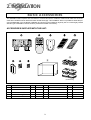
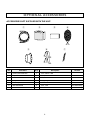
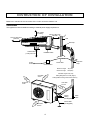
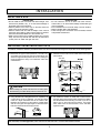
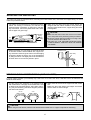
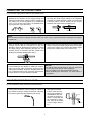
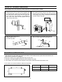
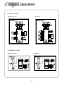
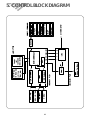
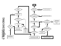
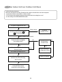
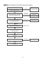
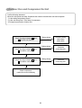
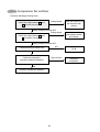
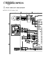
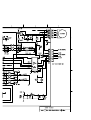
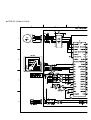
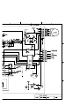
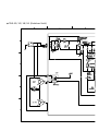
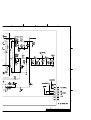
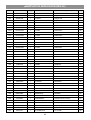
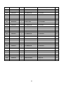
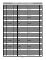
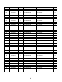
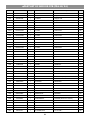
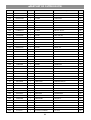
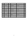
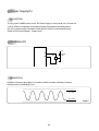
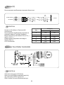
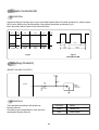
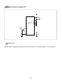
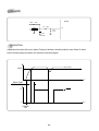
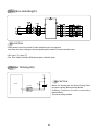
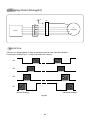
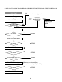
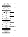
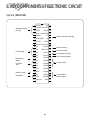
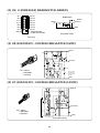
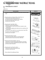
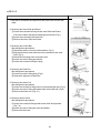
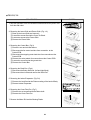
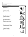
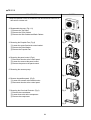
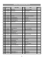
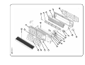
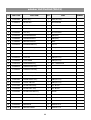
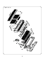
1. SPECIFICATIONS
ITEM
TAS-12
TAS-15
Function
TAS-18
TAS-24
Cooling
Capacity
BTU/H
SEER
Dehuminication
L/H
11500
15000
18000
22000
10.6
10.3
10.3
10.0
1.5
1.8
2.5
3.0
Electrical Data
AC 208/230V~ , 60Hz , 1 Ph
Main Power
Running Current
A
4.5
6.4
7.5
9.5
Watts
W
1010
1420
1060
2110
42.3 (1200g)
63.5 (1800g)
Refrigerant
R-22
Quantity
OZ
35.3 (1000g)
40.5 (1150g)
Connection
Flare
Gas Side
inch
3/8" (9.52mm)
1/2" (12.7mm)
1/2" (12.7mm)
5/8" (15.9mm)
Liquid Side
inch
1/4" (6.35mm)
1/4" (6.35mm)
1/4" (6.35mm)
3/8" (9.52mm)
QK164KBD
RCA155U001
RCA180U001
QP325KBB
MRA 98996-12026
MRA 12013-696
MRA 12138-696
Internal
24
39
42
68
Indoor
FDA353DWA
FDA353DWB
Outdoor
YDK-50-6B1
YDK-50-6B1
YDK-50-6B1
A2929GS010
3/30µF 400VAC
3/30µF 400VAC
3/35µF 400VAC
5/40µF 400VAC
Compressor
O.L.P
LRA
Motor
A
Capacitor Dual
Dimension
Indoor
Unit conversion : 1 inch = 25.4 mm
WxHxD
mm
815x285x195
1035x322x205
1080x298x200
1080°ø298°ø200
lb
20.3 (9.2kg)
26.7 (12.1kg)
32.4 (14.7kg)
32.4 (14.7kg)
mm
800x615x320
800x615x320
800x615x320
872x675x325
lb
110.3 (50kg)
110.3 (50kg)
110.3 (50kg)
141.1 (64kg)
Weight (net)
Outdoor
FDA353DWC
WxHxD
Weight (net)
❃ The Ranges of Temperature And Humidity.
Indoor Temp
Outdoor Temp
Indoor Humidity
65~90°F
70~109°F
Less than 80%
(18~32°C)
(21~43°C)
❃ Standard Rating Condition
Indoor
1
Outdoor
DB
WB
DB
WB
80°F
67°F
94°F
75°F
(26.7°C)
(19.4°C)
(35.0°C)
(23.9°C)
2. INSTALLATION
BASIC ACCESSORIES
This Installation section explains how and where to connect this new air conditioner. Please read make sure all accessories are included as shown below and read manual thoroughly. This Installation section is provided to assist the person knowledgeable in air conditioner installation and should not be installed by anybody who is not thoroughly familiar
with this type of installation. Please contact a professional installer if necessary.
ACCESSORIES SUPPLIED WITH THE UNIT:
AUTO
0
9
(24 Series Only)
No
1
2
3
4
5
Part Name
Installation Plate
Remote Controller
Remote Holder
Deodorizing Filter
Electrostatic Filter
Q'ty
1
1
1
1
1
Remark
No
6
7
8
9
10
2
Part Name
Battery
Nail
Screw
Outdoor Cover
Foot Cushion
Q'ty
2
4
4
1
4
Remark
OPTIONAL ACCESSORIES
ACCESSORIES NOT SUPPLIED WITH THE UNIT:
1
2
3
5
No
Part Name
6
Q'ty
4
7
Description
Remark
1
Drain Hose Extension
1
PVC, 20mm x 2M
2
Tape Finish
1
PVC, W80mm x 25M
3
Insulator Plate
1
PE, T8.0
4
Putty
1
Gray, 80g
5
Wall Cap
1
HIPS,
6
Bracket Saddle
2
SCT, T0.8
24 Series Only
7
Cable Tie
2
DACT-190A
24 Series Only
3
INSTRUCTION OF INSTALLATION
Below is an overview for the connection of the Indoor unit to the Outdoor unit.
OVERVIEW
This appliance must be installed according to national power supply acquirement.
10cm (3.95in)
from ceiling
30cm (11.8in) from
side wall
10cm (3.95in) from
side wall
Wall
Wall Cap
At least 30cm
(11.8in) from unit
Installation Plate
Power
Source
Wrap with
Tape
Power cable
Circuit Breaker
Maximum Height
Maximum Length
1
cm 0
more than 1
cm 0
4 inch
more than
4 inch
7M (21Ft)
15M (49Ft)
Standard Length: 25ft (7.6m)
Adding Refrigerant: 0.32 oz/ft (30g/m)
Adding additonal tubing will decrease efficiency.
70
cm
more than
27 inch
Copper
Tubing
(Not Supplied)
60
cm
Ground Wire
(Not Supplied)
more than
24 inch
4
Drain
Hose
INSTALLATION
SELECTING A SITE:
OUTDOOR UNIT
• Do not install the unit in an area near heat sources,
exhaust fans, or an area where leakage of flammable gas
may be expected.
• Do not install the unit in a humid, damp or uneven location.
• Select a location that is well ventilated .
• Leave enough room around the unit for air intake, exhaust
and possible maintenance.
INDOOR UNIT
• Do not install the unit in an area with direct sunlight, near
heat sources (radiator, etc.), or an area where leakage of
flammable gas may be expected.
• Select a position in the room, high on the wall, where the
whole room can be uniformly cooled.
• Select a location that can hold the weight of the unit and
where the copper tubing, drain hose and Indoor to Outdoor
Wire have the shortest distance to the Outdoor unit.
• Make sure the Indoor unit is installed at least 10cm (3.95in)
away from the top and left side wall and at least 30cm
(11.8in) from AC outlet and right side wall.
INSTALLING THE INSTALLATION PLATE
To install the wall bracket, follow the procedures below. One hole is required for the tubing and may be either on the left or right side.
1. Determine the type of wall (sheetrock, concrete, etc.)
and make sure it is strong enough to hold indoor unit.
Select an approximate position for the unit, taking the
required distances away from walls/AC outlet into
consideration.
2. Determine if the hole is to be made at the left or right
hole location.
• TAS-18/24
• TAS-15
• TAS-12
CAUTION
• Before making hole, make sure there are no studs, pipes,
electrical wiring or conduit directly behind the area to be cut.
70(2.75)
3. Using drill with hole-cutting attachment or equivalent, cut
a hole 70mm (2.75") in diameter. The hole should be
made at a slight downward slant to the outdoor side.
Measure the thickness from the inside to outside edges
and cut a PVC pipe at a slight angle 1/4" shorter than the
thickness of the wall and insert pipe in wall.
Indoor
4. For sheetrock, wooden or similar wall, measure down
from the ceiling using a level or tape measure and attach
the wall bracket to the wall using 4 screws. If you are not
able to line up the holes with the beams, use toggle
bolts. Make sure the wall bracket is even and flush
against the wall.
Outdoor
Cut at slight angle
For Concrete, or similar type wall, make holes into the wall and insert concrete nails instead of screws.
5
MOUNTING THE INDOOR UNIT
The Indoor unit must be mounted before connecting the indoor/outdoor wire, drain hose and copper tubing. To mount,
follow the procedures below:
1. The tubing can be extended in 4 directions as shown
below. No cutting is necessary for left/rear and
right/rear tubing connections. If using left or right tubing connections, remove the plastic area with a hacksaw so pipes can go through.
2. Make sure the drain hose and copper tubing are
wrapped with the rubber insulation. Using the tape,
wrap the indoor/outdoor wire, copper tubing and drain
hose together.
CAUTION:
Left
Tubing
Right/Rear
Tubing
Left/Rear
Tubing
• Make sure the Indoor unit’s AC cord is not connected to AC power when performing these procedures.
• Be sure to comply with local codes on running a wire
from the indoor to the outdoor unit.
• DO NOT LET THE INDOOR/OUTDOOR WIRE
COME IN DIRECT CONTACT WITH THE TUBING
OR HOSE!
Right
Tubing
3. Shape the tubing so it can easily go through the hole
in the wall. Push the indoor/outdoor wire, copper tubing and drain hose through the hole in the wall angling
downward. Situate the indoor unit on the wall bracket
by lifting the indoor unit slightly above the wall bracket
and then down so it is securely locked in place.
Installation Plate
Insert Putty
Drain Hose
PREPARING THE COPPER TUBING (NOT INCLUDED)
A copper tubing extension (not included) may need to be cut. If this is the case, it will also have to be deburred and
flared as shown below:
1. Cut the copper tube extension to the desired length
with a tube cutter. It is highly recommended that 1 foot
is added to the requested length. After cutting, deburring may be necessary (see below diagram). Perform
this with a tube reamer.
BEFORE
2. Make a flare at the end of the copper tube with a flare
tool.
Make sure the inside surface and edges are smooth
and the sides are uniform length.
AFTER
Flare nut
Connection
pipe
Flare tool
CAUTION:
• When using the tube reamer, hold the tube downward and make sure no copper scraps fall into the tubing.
6
CONNECTING THE COPPER TUBES
To connect the copper tubes, follow the procedures below:
1. Remove the flare nut stoppers from the inside unit.
Determine the location of the copper tubing and
where the bends will be. Gently bend the copper tubing, making sure to use big angles so no crimping will
occur. Try to do this on the first try as repeated bending may break or crimp the tubing.
2. Remove the plastic stoppers from the tubing. Connect
the large and small copper tubing to the respective
extension and rotate the flare nut with your finger until
a smooth match is made. Make sure the copper
extension has foam rubber (insulation) on it.
coupler
Flare Nut
NOTE:
When removing the flare nut stopper from the inside unit, confirm “Ping”, sounds because the mixed gas is charged in
the inside unit,
3. Once a smooth match is made, tighten the flare nut
using a wrench. Be very careful not to strip the
threads or flare nut. Repeat this process for the small
and large tubing. When tightening the flare nut, use
another wrench to securely hold the coupler from
twisting and possibly damaging the tubing.
4. Remove the flare nut stoppers from the outdoor unit’s
valves. Connect the larger copper tubing to the larger
valve on the outdoor unit. Connect the smaller copper
tubing to the smaller valve on the outdoor unit.
5. Perform a leak test on all copper tube connections. To
prevent heat loss and damage to walls from condensation, the copper tube connections coming from the
wall must be insulated. Do this by wrapping foam rubber or equivalent around the connection approximately 8mm thick so no copper tubing is exposed.
NOTES:
• As with all wiring and hookups on this unit, make sure
the AC plug on the indoor unit is unplugged.
• Be very careful not to strip the threads or flare nut.
• When insulating the connections, use foam rubber or
equivalent.
CONNECTING THE DRAIN HOSE
To connect the drain hose, follow the procedures below:
1. Connect the drain hose extension to the drain hose
coming from the indoor unit by loosing the clamp on
the extension using a phillips screwdriver, attaching
the hoses together and then tightening the clamp.
2. Run the drain hose, slanted downward, outside. If the
drain pipe is exposed
indoors, make sure it is
thoroughly insulated so
Insert Putty
condensation does not
ruin walls or furniture or
come in contact with the
AC connection or extension. Also, do not crease
Drain Hose
or form a trap in the tubing.
7
CONNECTING THE CABLES
One electric power cable must be connected to the outdoor unit. The indoor unit is connected to outdoor unit through the
connection cable. To install the cables follow as below.
1. Open the connection cover on the indoor unit.
2. Open the SVC cover on the side of outdoor unit.
3. Connect the connection cable to terminal blocks of the indoor and outdoor unit as shown below.
- Must be connected with the same terminal number of indoor and outdoor unit.
- Be sure not to slip the cables out of terminal.
4. Connect the power cable and earth cable.
5. Reinstall the connection cover and the SVC cover.
6. Install the conduit kit. (The conduit kit is optional)
[Connetion Cable]
Indoor Unit
Terminal Block
1
2
3
4
5
1
2
3
4
5
Circuit breaker
(Main Power)
Terminal Block
Outdoor Unit
CAUTION
• The supply voltage must be the same as the rated voltage of air conditioner.
• Prepare the power source for exclusive use with the air conditioner.
• A circuit breaker must be installed between the power source and the unit.
• This air conditioner must be installed according to the national electric rules.
INFORMATION
• The information for the cables of this air conditioner is as below.
ITEM
POWER CABLE
CONNECTION CABLE
CONDUIT SIZE
SPECIFICATIONS
12K~15K BTU/h
3G AWG 14 SJT or SPT-3
18K~24K BTU/h
3G AWG 12 SJT or SPT-3
5G AWG 16~18 SJT
12K~24K BTU/h
3G AWG 18~20 SJT+2G AWG 16~18 SJT
0.875 inch (22.2mm)
8
1
2
T/B 2
TAPING UP THE WIRE/TUBES/HOSE
After running the wire, hose and tubing outside, tape them up as shown below to insulate.
1. Tape the two copper tubes, drain hose (and the
electrical wiring if local codes permit) together with
the supplied tape. Make sure the electrical wiring
does not come in direct contact with the copper tubing or drain hose. Approximately 1 foot outside the
hole, let the drain hose out and separate from the
copper tubing and wiring.
2. Begin wrapping from the point the tubing comes out of
the outdoor unit and continue to the hole in the wall.
Leave no gaps or breaks and cover the entire length
of the tubing. As you wrap, overlap the previous turn
by half the width of the tape.
Drain hose
3. Wrap the piping joints with the
insulator plate and fas
ten it with vinyl tape.
4. After wrapping the connection pipe with tape,
fasten it to the outside wall with saddles, etc.
Plate
Wall cap
Pipe
pipe
Tape
vinyl tape
Saddle
(Not supplied)
MOUNTING OUTDOOR UNIT
1. After selection the appropriate site, position the outdoor unit and make sure the space around the outdoor unit.
(See overview instruction of installation)
2. Mount the outdoor unit on appropriate base using anchor bolts.
3. Install the CUSHION RUBBER provided to prevent vibration and noise.
4. If the outdoor unit is expose to direct sunlight or strong wind, install shield around the outdoor units.
❈ The outdoor unit must be installed on stable and rigid base.
9
Model
A
B
TAS-12/15/18
360
580
TAS-24
350
550
APPLYING PUTTY AND INSERTING THE WALL CAP
After running the wires and tubing outside, putty should be inserted around the opening on the outside to protect against
rain, wind, etc. To apply putty, see below:
1. Apply the putty to any area
on the outside hole that air
or rain can get into.
2. After applying putty,
insert the wall Cap at
Indoor side
and Outdoor side.
Apply Putty
Here
Insert Putty
Wall Cap
(For DS-110R)
Tubing
Indoor side
Drain Hose
Wall
Outdoor side
Indoor Unit
AIR PURGING
Air and moisture remaining in the refrigerant system may create adverse conditions
as indicated below:
Outdoor Unit
• pressure in the system rises
• operating current rises
• cooling efficiency drops
• moisture in the refrigerant circuit may freeze and block capillary tubing
• water may lead to corrosion of parts in the refrigerant system
Therefore, the indoor unit and tubing between the indoor and outdoor unit must
be leak tested and evacuated to remove any noncondesables and moisture from
the system.
Manifold Valve
Pressure
Gauge
Lo
Hi
AIR PURGING WITH VACUUM PUMP (TEST RUN)
Confirm each tube (narrow and wide tubes) between the indoor and outdoor units
has been properly connected and all wiring for the test run has been completed.
Remove the valve caps from the wide and narrow service valves on the
outdoor unit. Note that both narrow and wide tube service valves on the outdoor
unit are kept closed at this stage (shipping position).
Leak Test
1. With the service valves on the outdoor unit remaining closed, remove the
threaded cover on the wide tube service port. (Save for reuse.)
2. Attach a manifold valve (with pressure gauge) and dry nitro gen gas cylinder
to this service port with charge hoses.
Charge Hose
Nitrogen Gas
Cylinder
(Vertical
Position)
CAUTION:
Be sure to use a manifold valve for air purging. If it is not avail able, use a stop valve for this purpose.
The “Hi” knob of the manifold valve must always be kept closed.
3. Pressurize the system to no more than 150 P.S.I.G. with dry nitrogen gas and close the cylinder valve when the
gauge reading reaches 150 P.S.I.G. Next, test for leaks with liquid soap.
CAUTION:
To avoid nitrogen entering the refrigerant system in a liquid
state, the top of the nitrogen gas cylinder must be higher than its bottom when you pressurize the system. Usually, the
cylinder is used in a vertical standing position.
4. Do a leak test of all joints of the tubing (both indoor and outdoor) and both wide and narrow service valves. Bubbles
indicate a leak. Be sure to wipe off the soap with a clean cloth.
5. After the system is found to be free of leaks, relieve the nitrogen pressure by loosening the charge hose connector at
the nitrogen cylinder. When the system pressure is reduced to normal, disconnect the hose from the cylinder.
10
Evacuation
Indoor Unit
1. Attach the charge hose end described in the leak test
area to a vacuum pump to evacuate the tubing and
indoor unit. Confirm the Lo knob of the manifold valve is
open. Then, run the vacuum pump. The operation time
for evacuation varies with the tubing length and capacity
of the pump. The following table shows the amount of
time for evacuation:
Outdoor Unit
Required time for evacuation when 30 gal/h vacuum
pump is used
If tubing length is less than
33 ft. (10 m)
If tubing length is longer than
33 ft. (10 m)
10 min. or more
15 min. or more
2. When the desired vacuum is reached, close the Lo knob
of the manifold valve and stop the vacuum pump.
Manifold Valve
Finishing the job
1. With a hex wrench, turn the narrow tube service valve Pressure
stem counter-clockwise to fully open the valve.
Gauge
2. Turn the wide tube service valve stem counter-clockwise
to fully open the valve.
Lo
Hi
CAUTION:
To avoid gas from leaking when removing the charge hose,
make sure the wide tube service valve is fully open and
turned all the way out.
3. Loosen the charge hose connected to the wide tube service port slightly to release the pressure, then remove the
hose.
4. Replace the threaded cover on the wide tube service port
and fasten it securely. This process is very important to
prevent gas from leaking from the system.
5. Replace the valve caps at both wide and narrow service
valves and fasten them securely.
This completes air purging with a vacuum pump. The air
conditioner is now ready to test run..
11
Charge Hose
Vacuum
Pump
TEST RUN
Check that all tubing and wiring have been completed correctly. Check again that the wide and narrow tube service
valves are fully opened. Turn on the power and run the system.
Service Valve Construction
• Valve Position Closed
The valve systems of both the wide and narrow tubes are turned all the way in. The unit is shipped from the factory in
this position and it is also used for Pump Down and Air Purging.
• Valve Position Fully Open
The valve stems of both the wide and narrow tubes are turned all the way out. This is normal operating and Test Run
position.
• Valve Position Half Open
With the narrow tube valve stem is turned to the halfway-down position. This position is used for pressure measurement and gas charging.
CAUTION:
When opening or closing the service valve stem, be sure to use a hex wrench.
PUMP DOWN
Pump Down means collecting all refrigerant in the outdoor unit without loss in refrigerant gas.
This is performed when the unit is to be relocated or the refrigerant circuit is serviced.
CAUTION:
Be sure to perform Pump Down procedure with the unit cooling mode.
Pump Down Procedure
1. Connect a low-pressure gauge manifold hose to the charge port on the wide tube service valve.
2. Open the wide tube service valve halfway and purge the air from the manifold hose using the refrigerant gas.
3. Close the narrow tube service valve (all the way in).
4. Turn on the unit s operating switch and start the cooling operation.
5. When the low-pressure gauge reading becomes 1 to 0.5 kg/cm2 (14.2 to 7.1 psi), fully close the wide tube valve stem
and then quickly turn off the unit. At that time, Pump Down has been completed and all refrigerant gas will have been
collected in the outdoor unit.
12
3. REFRIGERANT CYCLE DIAGRAM
13
4. WIRING DIAGRAM
• Indoor Unit
◆ TAS-12/18/24
◆ TAS-15
• Outdoor Unit
◆ TAS-12/15/18
◆ TAS-24
14
5. CONTROL BLOCK DIAGRAM
15
Trouble
Is the
unit display
normal?
Is the power
applied to the
unit
Outdoor unit does
not run?
Is the
power normal?
check the voltage between
L & N of terminal
block
Does
the compressor run
normally?
NO
YES
NO
YES
Check the failure
code according to
the self diagnostic
Check the wiring of indoor
YES
Is the
switch position
on switch pannel at
"Remote"
press the power ON/OFF
button on remote controller
YES
Is the unit
display
mormal?
NO
NO
YES
NO
YES
NO
Does the
beeper beep two
times?
Normal
check the
connecting
point of
magnetic
contactor
YES
NO
Is the display
all off?
NO
Does
control PCB
status LED repeat one
second "on and
off"?
• control PCB fault
• Micom or reset
IC fault
YES
YES
check the failure
code according to
the self-diagonostic
• Check the connector on display
PCB connected to control PCB
• Check the display PCB itself
• Check the remote signal receiver
• Check the connection between signal
receiver and control PCB
Place the switch
position to the
"Remote" and then
Check it once
more
16
6. TROUBLE SHOOTING
YES
Indoor unit does
not run
Check power supply mains
or interconnection wires
YES
YES
NO
NO
Note 1)
1 Neither indoor unit nor outdoor unit runs.
Check the following points first. (There are following case in normal operation)
a. Is the timer mode set the "timer ON".
b. Is the timer mode set the "timer-OFF" and the time had passed?
2 Neither outdoor fan nor compressor runs while indoor fan runs.
Check following points first. (There are following cases in normal operation)
a. Is the temperature set point suitable?
b. Has the 3 minutes time guard for compressor operated?
Self-Diagnostic Function
1. Error Code I - ON LED blinking 3 times at Emergency Mode
1 When the compressor do not run.
i) Check the voltage between L and Y of terminal block.
(Indoor Unit, Outdoor Unit)
ii) Check connecting wire of indoor unit and outdoor unit.
iii) Check relay RL1 on power P.C.B (outdoor PCB)
2 Check fixing of indoor coil thermistor.
3 Check the GAS LEAKAGE of the pipe.
2. Error Code 2 - ON LED blinking
1 Check the sensor and its circuit.
2 It occurs when sensor is open or short.
3. Error Code 3 – TIMER LED blinking
1 Check the Indoor Fan Motor.
2 Check the RPM feedback circuit.
③ Indoor Fan Motor does not work for 5 seconds.
17
Neither Indoor Unit nor Outdoor Unit Runs
Confirm following statement.
When the unit operate normally, Sometimes the outdoor unit and indoor unit cannot operate.
1 Check the function select switch. Is it timer mode?
2 The function select switch locate the sleep mode and is the setting time over?
3 Is the setting mode DEHUMIDIFIER mode?
The power is applied to the unit
Rating voltage
Check the voltge between L and
Y of terminal block
under 90%
Check the
Breaker or Fuse
Rating voltage more than 90%
No
Check the indoor unit display
is the display all off?
Yes
Press the ON/OFF switch of
Remote Control
No
Self Diagnostic
function is ON
Yes
No
Check according to
self Diagnostic function
Is the indoor unit display all off?
Control P.C.B defect
Pull out the power plug
and then insert the power plug
after 5 second
Control P.C.B is normal
Recheck from the beginning
18
Outdoor Unit Runs but Indoor Fan Do Not Run
Check rotation of indoor fan
NO
Check the Fan Motor
bearing and fan
DC 30V(Vs),
DC 15V(Vc)
Check the power P.C.B.
(outdoor PCB)
Rotate indoor fan by hand
YES
Check input Voltage (Vs) of Fan
Motor connector at power P.C.B
Fail
The circuit for DC POWER
DC POWER OK
Open or short
Check the winding resistance of
Indoor unit fan motor
Change of fan motor
Normal
Check the Vsp of indoor PCB
❈ Vsp=0~5V DC
Check the connecting wire of
indoor fan motor
Run again
No
Check the starting of indoor fan motor
Run again
19
Normal
Outdoor Fan and Compressor Do Not
Confirm following statement.
When the unit operate normally, Sometimes the outdoor unit and indoor unit cannot operate.
1 Is the setting temperature proper?
2 Is the unit during 3min. Time delay of compressor.
3 During frost prevention of lndoor unit.
Rating voltage
Check the voltge between L and
Y of indoor unit terminal
under 90%
Rating voltage
Check the voltge between L and
Y of outdoor unit terminal
under 90%
Check the voltge between L and
Y of outdoor unit terminal
Rating voltage
under 90%
Check compressor,
outdoor fan motor individually
20
Check the wiring
and voltage
within doors
Check the
connecting wire
Check the
connecting wire
Only Compressor Do not Run
- Check the following at cooling mode
Rating voltage
Check the voltge between L and
Y of indoor unit terminal
less than 90%
Check the control P.C.B
the circuit for relay
driving.
Rating voltage more than 90%
Rating voltage
Check the voltge between L and
Y of outdoor unit terminal
less than 90%
Check the connecting
wire between indoor
and outdoor.
Rating voltage more than 90%
Check the wiring of outdoor unit
Check the compressor
(Check the winding resistance)
OK
Check the compressor capacitor
21
NG
Change the control
P.C.B
Open or Short
Change the
compressor.
7. PCB DESCRIPTION
1 PCB CIRCUIT DIAGRAM
◆ TAS-12/18/24 (Indoor Unit)
◆ TAS-15 (Indoor Unit)
◆ TAS-12/15/18/24 (Outdoor Unit)
◆PART LIST OF INDOOR PCB (TAS-12)
Location
Part Code
Q'ty
Part Name
BZ1
3105698200
1
BUZZER
DP-2520BA
EA
CA1
CN5XD104M-
1
C-ARRAY
6P(F5)X 104Z
EA
CA2
CN4XD104M-
1
C-ARRAY
5P(F4)X 104Z
EA
CA3
CN3XD104M-
1
C-ARRAY
4P(F3)X 104Z
EA
CC1
CCXE1H104M
1
C-CERA
104M 50VDC
EA
CC10
CCXE1H104M
1
C-CERA
104M 50VDC
EA
CC11
CCXE1H104M
1
C-CERA
104M 50VDC
EA
CC12
CCXE1H104M
1
C-CERA
104M 50VDC
EA
CC2
CCXE1H104M
1
C-CERA
104M 50VDC
EA
CC3
CCXE1H104M
1
C-CERA
104M 50VDC
EA
CC4
CCXE1H103M
1
C-CERA
103M 50VDC
EA
CC6
CCXE1H103M
1
C-CERA
103M 50VDC
EA
CC7
CCXE1H103M
1
C-CERA
103M 50VDC
EA
CC8
CCXE1H103M
1
C-CERA
103M 50VDC
EA
CC9
CCXE1H104M
1
C-CERA
104M 50VDC
EA
CE1
CEXE1E107C
1
C-ELEC
100UF 25V
EA
CE2
CEXE1E107C
1
C-ELEC
100UF 25V
EA
CE3
CEXE1C106A
1
C-ELEC
10MF 16V SS
EA
CE4
CEXE1C475A
1
C-ELEC
4.7MF 50V SS
EA
CE5
CEXE1E476C
1
C ELEC
47UF 25V SG
EA
CN1
3108803200
1
WAFER
YW396-06V
EA
CN2
3108803100
1
WAFER
YW396-05V
EA
CN3
3118702310
1
WAFER
YMAW025-04R
EA
CN4
3108804800
1
WAFER
SMAW250-08
EA
CN5
3118700800
1
WAFER
SMAW250-06
EA
D1
DZN4148FTB
1
DIODE
1N4148 AUTO 26MM
EA
IC1
13GS87PH46
1
IC MICOM
TMP87PH46N(OTP)
EA
IC2
1L7805CV--
1
IC REGULATOR
L7805CV
EA
IC3
1KD65004AP
1
IC DRIVER
KID65004AP
EA
IC4
1KD65004AP
1
IC DRIVER
KID65004AP
EA
IC5
1KA7042P--
1
IC RESET
KIA7042P 5L
EA
JS2
3109400100
1
JUMPER
10MM
EA
JS3
3109400100
1
JUMPER
10MM
EA
OSC
5PRT800MG-
1
RESONATOR
RT8.00MG
EA
PC1
1LTV817C--
1
IC PHOTO COUPLER
LTV-817C
EA
PCB
3114308210
1
PCB CONTROL
TAS12(176.5*121*1.6T,FR1)
EA
R1
RD-2K102J-
1
RESISTOR
1/2W - 1K
EA
R10
RD-4K102J-
1
R CARBON FILM
1/4 1K OHM J
EA
R11
RD-4K102J-
1
R CARBON FILM
1/4 1K OHM J
EA
R12
RD-4K102J-
1
R CARBON FILM
1/4 1K OHM J
EA
R13
RD-4K102J-
1
R CARBON FILM
1/4 1K OHM J
EA
26
Description
Unit
Location
Part Code
Q'ty
Part Name
R14
RD-4K102J-
1
R CARBON FILM
1/4 1K OHM J
EA
R15
RD-4K102J-
1
R CARBON FILM
1/4 1K OHM J
EA
R16
RD-4K102J-
1
R CARBON FILM
1/4 1K OHM J
EA
R17
RD-4K102J-
1
R CARBON FILM
1/4 1K OHM J
EA
R18
RD-4K102J-
1
R CARBON FILM
1/4 1K OHM J
EA
R19
RD-4K102J-
1
R CARBON FILM
1/4 1K OHM J
EA
R2
RN-4K1001F
1
R METAL FILM
1/4 1K OHM F
EA
R21
RN-4K5761F
1
R METAL FILM
1/4 5.76K OHM F
EA
R23
RN-4K2432F
1
R METAL FILM
1/4 24.3K OHM F
EA
R25
RD-4K102J-
1
R CARBON FILM
1/4 1K OHM J
EA
R26
RD-4K102J-
1
R CARBON FILM
1/4 1K OHM J
EA
R27
RD-4K102J-
1
R CARBON FILM
1/4 1K OHM J
EA
R28
RD-4K102J-
1
R CARBON FILM
1/4 1K OHM J
EA
R3
RN-4K1501F
1
R METAL FILM
1/4 1.5K OHM F
EA
R31
RD-4K331J-
1
R CARBON FILM
1/4 330 OHM J
EA
R32
RN-4K1272F
1
R METAL FILM
1/4 12.7K OHM F
EA
R33
RD-4K331J-
1
R CARBON FILM
1/4 330 OHM J
EA
R34
RN-4K1272F
1
R METAL FILM
1/4 12.7K OHM F
EA
R35
RD-4K102J-
1
R CARBON FILM
1/4 1K OHM J
EA
R36
RD-4K562J-
1
R CARBON FILM
1/4 5.6K OHM J
EA
R37
RD-4K102J-
1
R CARBON FILM
1/4 1K OHM J
EA
R4
RD-4K331J-
1
R CARBON FILM
1/4 330 OHM J
EA
R5
RD-4K103J-
1
R CARBON FILM
1/4 10K OHM J
EA
R6
RD-4K102J-
1
R CARBON FILM
1/4 1K OHM J
EA
R7
RD-4K102J-
1
R CARBON FILM
1/4 1K OHM J
EA
R8
RD-4K102J-
1
R CARBON FILM
1/4 1K OHM J
EA
R9
RD-4K102J-
1
R CARBON FILM
1/4 1K OHM J
EA
RA1
RA8K5103J-
1
RESISTOR ARRAY
6P(5)X 103J
EA
RA2
RA8K4103J-
1
RESISTOR ARRAY
5P(4)X 103J
EA
RA3
RA8K3103J-
1
RESISTOR ARRAY
4P(3)X 103J
EA
27
Description
Unit
◆PART LIST OF INDOOR PCB (TAS-15)
Location
Part Code
Q'ty
Part Name
BZ1
3105698200
1
BUZZER
DP-2520BA
EA
CA1
CN5XD104M-
1
C-ARRAY
6P(F5)X 104Z
EA
CA2
CN3XD104M-
1
C-ARRAY
4P(F3)X 104Z
EA
CC1
CCXE1H104M
1
C-CERA
104M 50VDC
EA
CC10
CCXE1H104M
1
C-CERA
104M 50VDC
EA
CC11
CCXE1H104M
1
C-CERA
104M 50VDC
EA
CC12
CCXE1H104M
1
C-CERA
104M 50VDC
EA
CC13
CCXE1H103M
1
C-CERA
103M 50VDC
EA
CC14
CCXE1H103M
1
C-CERA
103M 50VDC
EA
CC15
CCXE1H103M
1
C-CERA
103M 50VDC
EA
CC16
CCXE1H103M
1
C-CERA
103M 50VDC
EA
CC2
CCXE1H104M
1
C-CERA
104M 50VDC
EA
CC3
CCXE1H104M
1
C-CERA
104M 50VDC
EA
CC4
CCXE1H103M
1
C-CERA
103M 50VDC
EA
CC6
CCXE1H103M
1
C-CERA
103M 50VDC
EA
CC7
CCXE1H103M
1
C-CERA
103M 50VDC
EA
CC8
CCXE1H103M
1
C-CERA
103M 50VDC
EA
CC9
CCXE1H104M
1
C-CERA
104M 50VDC
EA
CE1
CEXE1E107C
1
C-ELEC
100UF 25V
EA
CE2
CEXE1E107C
1
C-ELEC
100UF 25V
EA
CE3
CEXE1C106A
1
C-ELEC
10MF 16V SS
EA
CE4
CEXE1C475A
1
C-ELEC
4.7MF 50V SS
EA
CE5
CEXE1E476C
1
C ELEC
47UF 25V SG
EA
CN1
3108803200
1
WAFER
YW396-06V
EA
CN2
3108803100
1
WAFER
YW396-05V
EA
CN3
3118702310
1
WAFER
YMAW025-04R
EA
CN4
3108804100
1
WAFER
SMW250-07
EA
CN5
3108802000
1
WAFER
SMW250-06
EA
CN7
3108804200
1
WAFER
SMW250-02
EA
CN8
3108802000
1
WAFER
SMW250-06
EA
D1
DZN4148FTB
1
DIODE
1N4148 AUTO 26MM
EA
IC1
13GS87PH46
1
IC MICOM
TMP87PH46N(OTP)
EA
IC2
1L7805CV--
1
IC REGULATOR
L7805CV
EA
IC3
1KD65004AP
1
IC DRIVER
KID65004AP
EA
IC4
1KD65004AP
1
IC DRIVER
KID65004AP
EA
IC5
1KA7042P--
1
IC RESET
KIA7042P 5L
EA
JS2
3109400100
1
JUMPER
10MM
EA
JS3
3109400100
1
JUMPER
10MM
EA
OSC
5PRT800MG-
1
RESONATOR
RT8.00MG
EA
PC1
1LTV817C--
1
IC PHOTO COUPLER
LTV-817C
EA
PCB
3114308310
1
PCB CONTROL
TAS15(110*130*1.6T,FR1)
EA
28
Description
Unit
Location
Part Code
Q'ty
Part Name
R1
RD-2K102J-
1
RESISTOR
1/2W - 1K
EA
R10
RD-4K102J-
1
R CARBON FILM
1/4 1K OHM J
EA
R11
RD-4K102J-
1
R CARBON FILM
1/4 1K OHM J
EA
R12
RD-4K102J-
1
R CARBON FILM
1/4 1K OHM J
EA
R13
RD-4K102J-
1
R CARBON FILM
1/4 1K OHM J
EA
R14
RD-4K102J-
1
R CARBON FILM
1/4 1K OHM J
EA
R15
RD-4K102J-
1
R CARBON FILM
1/4 1K OHM J
EA
R16
RD-4K102J-
1
R CARBON FILM
1/4 1K OHM J
EA
R17
RD-4K102J-
1
R CARBON FILM
1/4 1K OHM J
EA
R18
RD-4K102J-
1
R CARBON FILM
1/4 1K OHM J
EA
R19
RD-4K102J-
1
R CARBON FILM
1/4 1K OHM J
EA
R2
RN-4K1001F
1
R METAL FILM
1/4 1K OHM F
EA
R21
RN-4K1022F
1
R METAL FILM
1/4 10.2K OHM F
EA
R23
RN-4K4122F
1
R METAL FILM
1/4 41.2K0HM F
EA
R25
RD-4K102J-
1
R CARBON FILM
1/4 1K OHM J
EA
R26
RD-4K102J-
1
R CARBON FILM
1/4 1K OHM J
EA
R27
RD-4K102J-
1
R CARBON FILM
1/4 1K OHM J
EA
R28
RD-4K102J-
1
R CARBON FILM
1/4 1K OHM J
EA
R3
RN-4K1501F
1
R METAL FILM
1/4 1.5K OHM F
EA
R31
RD-4K331J-
1
R CARBON FILM
1/4 330 OHM J
EA
R32
RN-4K1272F
1
R METAL FILM
1/4 12.7K OHM F
EA
R33
RD-4K331J-
1
R CARBON FILM
1/4 330 OHM J
EA
R34
RN-4K1272F
1
R METAL FILM
1/4 12.7K OHM F
EA
R35
RD-4K102J-
1
R CARBON FILM
1/4 1K OHM J
EA
R36
RD-4K562J-
1
R CARBON FILM
1/4 5.6K OHM J
EA
R37
RD-4K102J-
1
R CARBON FILM
1/4 1K OHM J
EA
R38
RD-4K103J-
1
R CARBON FILM
1/4 10K OHM J
EA
R39
RD-4K103J-
1
R CARBON FILM
1/4 10K OHM J
EA
R4
RD-4K331J-
1
R CARBON FILM
1/4 330 OHM J
EA
R40
RD-4K103J-
1
R CARBON FILM
1/4 10K OHM J
EA
R41
RD-4K103J-
1
R CARBON FILM
1/4 10K OHM J
EA
R5
RD-4K103J-
1
R CARBON FILM
1/4 10K OHM J
EA
R6
RD-4K102J-
1
R CARBON FILM
1/4 1K OHM J
EA
R7
RD-4K102J-
1
R CARBON FILM
1/4 1K OHM J
EA
R8
RD-4K102J-
1
R CARBON FILM
1/4 1K OHM J
EA
R9
RD-4K102J-
1
R CARBON FILM
1/4 1K OHM J
EA
RA1
RA8K5103J-
1
RESISTOR ARRAY
6P(5)X 103J
EA
RA2
RA8K3103J-
1
RESISTOR ARRAY
4P(3)X 103J
EA
29
Description
Unit
◆PART LIST OF INDOOR PCB (TAS-18/24)
Location
Part Code
Q'ty
Part Name
BZ1
3105698200
1
BUZZER
DP-2520BA
EA
CA1
CN5XD104M-
1
C-ARRAY
6P(F5)X 104Z
EA
CA2
CN4XD104M-
1
C-ARRAY
5P(F4)X 104Z
EA
CA3
CN3XD104M-
1
C-ARRAY
4P(F3)X 104Z
EA
CC1
CCXE1H104M
1
C-CERA
104M 50VDC
EA
CC10
CCXE1H104M
1
C-CERA
104M 50VDC
EA
CC11
CCXE1H104M
1
C-CERA
104M 50VDC
EA
CC12
CCXE1H104M
1
C-CERA
104M 50VDC
EA
CC2
CCXE1H104M
1
C-CERA
104M 50VDC
EA
CC3
CCXE1H104M
1
C-CERA
104M 50VDC
EA
CC4
CCXE1H103M
1
C-CERA
103M 50VDC
EA
CC6
CCXE1H103M
1
C-CERA
103M 50VDC
EA
CC7
CCXE1H103M
1
C-CERA
103M 50VDC
EA
CC8
CCXE1H103M
1
C-CERA
103M 50VDC
EA
CC9
CCXE1H104M
1
C-CERA
104M 50VDC
EA
CE1
CEXE1E107C
1
C-ELEC
100UF 25V
EA
CE2
CEXE1E107C
1
C-ELEC
100UF 25V
EA
CE3
CEXE1C106A
1
C-ELEC
10MF 16V SS
EA
CE4
CEXE1C475A
1
C-ELEC
4.7MF 50V SS
EA
CE5
CEXE1E476C
1
C ELEC
47UF 25V SG
EA
CN1
3108803200
1
WAFER
YW396-06V
EA
CN2
3108803100
1
WAFER
YW396-05V
EA
CN3
3118702310
1
WAFER
YMAW025-04R
EA
CN4
3108804800
1
WAFER
SMAW250-08
EA
CN5
3118700800
1
WAFER
SMAW250-06
EA
D1
DZN4148FTB
1
DIODE
1N4148 AUTO 26MM
EA
IC1
13GS87PH46
1
IC MICOM
TMP87PH46N(OTP)
EA
IC2
1L7805CV--
1
IC REGULATOR
L7805CV
EA
IC3
1KD65004AP
1
IC DRIVER
KID65004AP
EA
IC4
1KD65004AP
1
IC DRIVER
KID65004AP
EA
IC5
1KA7042P--
1
IC RESET
KIA7042P 5L
EA
JS2
3109400100
1
JUMPER
10MM
EA
JS3
3109400100
1
JUMPER
10MM
EA
OSC
5PRT800MG-
1
RESONATOR
RT8.00MG
EA
PC1
1LTV817C--
1
IC PHOTO COUPLER
LTV-817C
EA
PCB
3114308410
1
PCB CONTROL
TAS18/24(163.25*123*1.6T,FR1)
EA
R1
RD-2K102J-
1
RESISTOR
1/2W - 1K
EA
R10
RD-4K102J-
1
R CARBON FILM
1/4 1K OHM J
EA
R11
RD-4K102J-
1
R CARBON FILM
1/4 1K OHM J
EA
R12
RD-4K102J-
1
R CARBON FILM
1/4 1K OHM J
EA
R13
RD-4K102J-
1
R CARBON FILM
1/4 1K OHM J
EA
30
Description
Unit
Location
Part Code
Q'ty
Part Name
R14
RD-4K102J-
1
R CARBON FILM
1/4 1K OHM J
EA
R15
RD-4K102J-
1
R CARBON FILM
1/4 1K OHM J
EA
R16
RD-4K102J-
1
R CARBON FILM
1/4 1K OHM J
EA
R17
RD-4K102J-
1
R CARBON FILM
1/4 1K OHM J
EA
R18
RD-4K102J-
1
R CARBON FILM
1/4 1K OHM J
EA
R19
RD-4K102J-
1
R CARBON FILM
1/4 1K OHM J
EA
R2
RN-4K1001F
1
R METAL FILM
1/4 1K OHM F
EA
R21
RN-4K5761F
1
R METAL FILM
1/4 5.76K OHM F
EA
R23
RN-4K2432F
1
R METAL FILM
1/4 24.3K OHM F
EA
R25
RD-4K102J-
1
R CARBON FILM
1/4 1K OHM J
EA
R26
RD-4K102J-
1
R CARBON FILM
1/4 1K OHM J
EA
R27
RD-4K102J-
1
R CARBON FILM
1/4 1K OHM J
EA
R28
RD-4K102J-
1
R CARBON FILM
1/4 1K OHM J
EA
R3
RN-4K1501F
1
R METAL FILM
1/4 1.5K OHM F
EA
R31
RD-4K331J-
1
R CARBON FILM
1/4 330 OHM J
EA
R32
RN-4K1272F
1
R METAL FILM
1/4 12.7K OHM F
EA
R33
RD-4K331J-
1
R CARBON FILM
1/4 330 OHM J
EA
R34
RN-4K1272F
1
R METAL FILM
1/4 12.7K OHM F
EA
R35
RD-4K102J-
1
R CARBON FILM
1/4 1K OHM J
EA
R36
RD-4K562J-
1
R CARBON FILM
1/4 5.6K OHM J
EA
R37
RD-4K102J-
1
R CARBON FILM
1/4 1K OHM J
EA
R4
RD-4K331J-
1
R CARBON FILM
1/4 330 OHM J
EA
R5
RD-4K103J-
1
R CARBON FILM
1/4 10K OHM J
EA
R6
RD-4K102J-
1
R CARBON FILM
1/4 1K OHM J
EA
R7
RD-4K102J-
1
R CARBON FILM
1/4 1K OHM J
EA
R8
RD-4K102J-
1
R CARBON FILM
1/4 1K OHM J
EA
R9
RD-4K102J-
1
R CARBON FILM
1/4 1K OHM J
EA
RA1
RA8K5103J-
1
RESISTOR ARRAY
6P(5)X 103J
EA
RA2
RA8K4103J-
1
RESISTOR ARRAY
5P(4)X 103J
EA
RA3
RA8K3103J-
1
RESISTOR ARRAY
4P(3)X 103J
EA
31
Description
Unit
◆PART LIST OF OUTDOOR PCB
Location
Part Code
Q'ty
Part Name
BD1
DKBJ408G--
1
DIODE BRIDGE
KBJ408G 4A 800V
EA
CC1
CH1BBN103K
1
C CERA
BN 103K 1KV DC
EA
CC2
CCXE1H104M
1
C-CERA
104M 50VDC
EA
CC3
CCXE1H104M
1
C-CERA
104M 50VDC
EA
CC4
CCXE1H104M
1
C-CERA
104M 50VDC
EA
CC5
CCXE1H104M
1
C-CERA
104M 50VDC
EA
CC6
CCXE1H104M
1
C-CERA
104M 50VDC
EA
CC7
CH1BBN221K
1
C CERA
BN 221K 1KV DC
EA
CC8
CH1BBN221K
1
C CERA
BN 221K 1KV DC
EA
CE1
CEXE2G686C
1
C-ELEC
68UF 400V SG
EA
CE10
CEXE1H226A
1
C-ELEC
22MF 50V
EA
CE2
CEXE1E476C
1
C ELEC
47UF 25V SG
EA
CE3
CEXE1H105A
1
C-ELEC
1UF 50V
EA
CE4
CEXE1H477C
1
C-ELEC
470UF 50V RX
EA
CE5
CEXE1H227C
1
C-ELEC
220UF, 50V
EA
CE6
CEXE1V337C
1
C-ELEC
330UF, 35V RX
EA
CE7
CEXE1V227C
1
C-ELEC
220UF 35V
EA
CE8
CEXE1E227C
1
C-ELEC
220UF 25V
EA
CE9
CEXE1E107C
1
C-ELEC
100UF 25V
EA
CL1
CLV-B3104M
1
C-LINE ACROSS
275V 104K(PILKOR)
EA
CLIP
3107000600
2
FUSE CLIP
AFC-520
EA
CN1
3108802500
1
WAFER
YW396-03AV
EA
CN2
3108803200
1
WAFER
YW396-06V
EA
D1
DP6KE200A-
1
DIODE TVS
P6KE200A
EA
D2
DUF1007---
1
DIODE UFR
UF1007, 1000V/1A
EA
D3
DZN4148FTB
1
DIODE
1N4148 AUTO 26MM
EA
D4
DHER503---
1
DIODE UFR
HER503, 200V/5A
EA
D5
DUF2003---
1
DIODE UFR
UF2003, 200V/2A
EA
F1
52F153K002
1
LINE FILTER
SQE2424,15MH,2A
EA
F2
52F2550R2-
1
FILTER BEAD
BFS2550 R2
EA
F3
52C3R3K000
1
CHOKE COIL
3.3UH,2A
EA
F4
52C3R3K000
1
CHOKE COIL
3.3UH,2A
EA
FUSE
5FVLB3152L
1
FUSE GLASS TUBE
250V/50T 3.15A
EA
HS1
3015700110
1
HEAT SINK
T35XW20XH40
EA
HS2
3015700110
1
HEAT SINK
T35XW20XH40
EA
HS3
3105797200
1
HEAT SHINK
22(H)*23*17
EA
IC1
1TP247YGX-
1
IC SMPS
TOP247Y-GX
EA
IC2
1L7815CV--
1
IC REGULATOR
L7815CV
EA
IC3
1L7812CV--
1
IC REGULATOR
L7812CV
EA
IC4
1K1A431---
1
IC REGULATOR
KIA431
EA
PC1
1LTV817C--
1
IC PHOTO COUPLER
LTV-817C
EA
32
Description
Unit
Location
Part Code
Q'ty
Part Name
PCB
3114308510
1
PCB POWER
TAS(170*89*1.6T,FR1)
EA
R1
RS02Y683J-
1
R M-OXIDE FILM
2W 68K OHM J
EA
R10
RD-4K271J-
1
R CARBON FILM
1/4 270 OHM J
EA
R11
RD-2K512J-
1
R CARBON FILM
1/2 5.1K OHM J
EA
R12
RD-4K153J-
1
R CARBON FILM
1/4 15K OHM J
EA
R13
RS02Y683J-
1
R M-OXIDE FILM
2W 68K OHM J
EA
R2
RD-4K105J-
1
R CARBON FILM
1/4 1M OHM J
EA
R3
RD-4K105J-
1
R CARBON FILM
1/4 1M OHM J
EA
R4
RD-4K689J-
1
R CARBON FILM
1/4 6.8 OHM J
EA
R5
RD-4K479J-
1
R CARBON FILM
1/4 4.7 OHM J
EA
R6
RD-4K102J-
1
R CARBON FILM
1/4 1K OHM J
EA
R7
RD-4K100J-
1
R CARBON FILM
1/4 10 OHM J AT26
EA
R8
RN-4K1002F
1
R METAL FILM
1/4 10.0K OHM F
EA
R9
RN-4K1103-
1
R METAL FILM
1/4W 110K OHM F
EA
RL1
5SC010141B
1
SW RELAY
PCF-112-D-1M
EA
TRS1
5EMU2834--
1
TRANS SMPS
265U,2834
EA
VAR
D15G561K--
1
VARISTOR
15G561K/350V
EA
YC1
CH1BFB222K
1
C CERA
2200PF,250V,Y1
EA
33
Description
Unit
Power Supply(1)
DESCRIPTION
The DC power is SMPS power source. DC Power Supply in circuit needs 30V, 15V and 12V.
+12V is used for Compressor Driving Relay, Buzzer Driving Swing and Swing Motor.
DC 30V is used for Indoor Fan Motor Power and DC 15V(Vc) is used for Motor Drive.
(Refer to PCB Circuit Diagram : Outdoor Unit)
Oscillator(2)
5V
19
OSC
20
CC13
104
8M
DESCRIPTION
Oscillatory Frequency drive Micom, it is made up 8MHz resonator oscillatory Freqency.
Ocillatory wave is as following Fig 2-1.
VDD-10%
VSS+10%
Fig 2-1
34
Sensor(3)
Room temperature and Evaporator temperature Sensor Input
103
CC6
ROOM SENSOR
I/D SENSOR
CN3
24
R10
12.7KF
R7 330
R11
12.7KF
R6 330
MICOM
25
CC5
103
DESCRIPTION
Voltage (V)
Temperature
Number 24, 25 of Micom is Terminal of A/D
convertor Input.
Room temperature and Evaporator temperature is
sensing by change of Thermister Resistance,
Micom is put in 5V by ratio between R10 (12.7KΩ)
and R11 (12.7KΩ).
Relation between temperature and voltage is
following Table 3-1.
CC5, 6 is Noise filter.
(°C)
No. 1
No. 3
-5
1.127
1.127
0
1.378
1.378
5
1.650
1.650
10
1.936
1.936
15
2.228
2.228
Table 3-1
Indoor Fan Motor Control(4)
DESCRIPTION
Indoor Fan motor power is DC30V(Vs)
Indoor Fan motor RPM is controled by Vsp(0~5V)
Vsp control pulse OUTPUT is Pin6, IC1
PIN31 is Indoor Fan motor RPM feed back input.
35
Remote Controller(5)
DESCRIPTION
Signal from Remote Controller put in only Control Data Signal at Micom Terminal of Number 33, which is gotten
fid of Carrier (38KHz) from Receive Module. Signal Wave repeat third as following Fig 5-1.
But in Secondary Wave Custom Code is Reversed Face.
9ms
4.5ms
16bit
24bit
8bit
16bit
0.56ms
LEADER CODE
CUSTOM
CODE
DATA
CODE
CHECK
SUM
1.69ms
1.12ms
bit 0
TAILER
2.25ms
bit 1
Fig 5-2
BIT STRUCTURE
Fig 5-1
Selecting Mode(6)
(SELECT S/W INPUT, OUTPUT)
5V
RA2
R25
1K
MICOM
MODE
SELECT
PUSH S/W
13
P2
CA2
F4104Z
DESCRIPTION
POSITION
There are Mode according to SW position as
following Table 6-1.
According as port of fixed Micom is Low, the unit is
operating as following Table 6-1.
MODE
OPEN
REMOCON
GND
EMERGENCY
Table 6-1
36
0.56ms
Micom Power Supply(7)
5V
VDD 42
CE3
10µF
16V
+
CC3
104
41
MICOM
OSC
8MHz
40
39
19
20
21
VSS
22
CC10
104
DESCRIPTION
MICOM Power is supplied 5V at Number 42 using VDD, Number 19, 20 Vsing Oscillator, CC10 is noise filter.
37
Reset(8)
MICOM
R38
5.6K
1K
R35
18
7042P
CC4
10.3
IC5
CE4
4.7uF/50V
DESCRIPTION
Voltage less than about 0.8V put in Micom Terminal of Number 18 and then Micom reset. Reset IC detect
Power ON and Voltage less than 4.25V, and then send Reset Signal.
Vcc (+5V)
4.25V
t
DELAY TIME
FOR POWER ON
H
RESET
L
t
POWER
ON
38
Function Selecting(9)
DESCRIPTION
* When power source is put at fist, Funtion selection input is recognized.
And when the unit is running the microcomputer ignore variation of funtion selection input.
• JS3: open (°C), short (°F)
• R21, R23: Indoot Fan Motor RPM select option with A/D signal.
Buzzer Driving(10)
VCC
12V
DESCRIPTION
MICOM
R37
1K
BZ1
KID 65004
34
6
11
39
Micom 34 Terminal put out Buzzer Driving Pulse,
its output is driving Buzzer through Buffer.
Ocillatory Frequency of buzzer is selected by
internal Micom.
This unit is setting at 4KHz.
Stepping Motor Driving(12)
12V
CN5
1
IC3
MICOM
B+
2
1
3
Ø1
2
4
Ø2
3
5
4
6
M1
FOR SWING
Ø3
Ø4
KID65004
DESCRIPTION
There are one Stepping Motor for Flap (up and down) and it is used 4 face Drive Method.
It is driving as following Fig 12-1. (Ring Count Method of 8 Status)
Ø4
Ø3
Ø2
Ø1
(Normal Rotating)
(Reversed Rotating)
Fig 12-1
40
• REMOTE CONTROLLER ASSMBLY FUNCTIONAL TEST METHOD
TEST START
No
Power supply again
Power Supply
Is Display at the
beginning ON?
Select ON/OFF button
Yes
Is Display at the
beginning ON?
No
Select Mode button
Is it normal?
No
ERROR
Select FAN SPEED button
Is it normal?
Select FAN DIR. button
Is it normal?
Is display at the
begining ON?
Select TEMP. Button (▲,▼)
Is it normal?
No
ERROR
( ▲)
▼
No
ERROR
No
ERROR
(Whenever you selectted Temp.
Button, it is changed by 1°C (18~32°C)
No
ERROR
Select ON/OFF button
41
No
Check the Following
BATTERY SPRING
MICOM
PCB
LCD
Is LCD display OFF?
No
ERROR
Select TIMER ON Button
Is it normal
No
ERROR
Select Timer Enter Button
TIMER display?
No
ERROR
Select CANCEL Button
Is all display OFF?
No
ERROR
Select ON/OFF Button
Select OFF (Timer) Button
Is it normal?
(0.5~24 HOUR)
No
ERROR
Select SLEEP Button
SLEEP MODE
Display ON?
No
ERROR
Select SLEEP Button
Is display at the
beginning ON?
No
ERROR
TEST OK!
42
8. KEY COMPONENTS OF ELECTRONIC CIRCUIT
(1) U1 (MICOM)
1 P77(HSO)
Steppping Motor
Driving
VDD 42
2 P76(HSCK) (XTOUT)P22 41
3 P75(SO)
(XTIN)P21 40
4 P74(SI) (INT5/STOP)P20 39
5 P73(SCK)
P17 38
6 P72(PDO/PWM)
P16 37
7 P71(INT4)
Indoor Unit Motor Driving
(TC2)P15 36
8 P70(INT3/TC3) (PPG)P14 35
9 P07
(DVO)P13 34
10 P06
(INT2/TC1)P12 33
11 P05
(INT1)P11 32
12 P04
(INTO)P10 31
Emergency
Mode
13 P03
(AIN7)P67 30
14 P02
(AIN6)P66 29
Function
S/W
15 P01
(AIN5)P65 28
16 P00
(AIN4)P64 27
17 TEST
(AIN3)P63 26
18 RESET
(AIN2)P62 25
19 XIN
(AIN1)P61 24
20 XOUT
(AIN0)P60 23
LED Driving
Reset Curcuit
Oscillation
21 (VASS)VSS
VAREF 22
43
Buzzer Driving
Remocon Input
Comp Relay Driving
Zero Crosing Detect
Function S/W
Temperature
Sensor Input
(2) U2, 4 (KID65004) DARLINGTON ARRAYS
16 OUT 1
15 OUT 2
14 OUT 3
13 OUT 4
12 OUT 5
11 OUT 6
10 OUT 7
9 COMMON FREE
WHEELING DIODES
KID65004AP
COMMON
INPUT
OUTPUT
10.5KΩ
7.2KΩ
3KΩ
IN1 1
IN2 2
IN 3 3
IN 4 4
IN5 5
IN6 6
IN7 7
GND 8
GND
(Equivalent Circuit)
(Top View)
(3) U8 (KIA7805P) : VOLTAGE REGULATOR (5VDC)
SCHEMATIC DIAGRAM
INPUT
100K
100
100
500
10K
240
200
3.3
K
1
2
3
1.4
K
Pin 1. INPUT
2. GROUND
3. OUTPUT
OUTPUT
2K
6K
2.7
K
0.3
0.19K
28K
30pF
5K
500
6K 1K
5K
Fin 2 is ground
for Cose 221A.
Case is ground
for Case 1.
GND
(4) U7 (KIA7812P) : VOLTAGE REGULATOR (12VDC)
10K
INPUT
10K
210
16K
100
300
200
36K
64K
300
50K
520
60K
012
40
pF
50
200
OUTPUT
26K
Pin 1. INPUT
2. GROUND
3. OUTPUT
20K
29K
20K
GND
(Equivalent Ciircuit)
44
(5) U9 (KIA7042P) : RESET IC
1 VCC
KIA70
42P
3 OUT
2 GND
INPUT
GROUND
OUTPUT
OUTLINE
45
9. DISASSEMBLY INSTRUCTIONS
1 INDOOR UNIT
◆TAS-12
PROCEDURES
PHOTOS
1. Stop the Air conditioner and disconnect the power cord from the wall
outlet.
Fig 1
2. Removing the Insert Grille and Frame Grille. (Fig 1~2)
1 Draw up the Insert Grille and remove it.
2 Loosen one screw for fixing the Cover Ter-Block.
3 Loosen two screw at the Frame Grille.
4 Remove the Frame Grille.
3. Removing the Control Box. (Fig 3)
1 Remove room and coil thermistors.
2 Disconnect the fan motor lead wire from connection at the
Control PCB.
3 Disconnect the stepping motor lead wire from connection at the
Control PCB.
4 Remove the select switch from connection at the Control PCB.
5 Loosen a screw for fixing ground wire.
6 Remove the Control Box
4. Removing the Drain Pan. (Fig 4)
1 Disconnect the Body drain hole. (left and right Body)
2 Disconnect three hook and remove the Drain Pan.
5. Removing the Indoor Evaporator. (Fig 5~6)
1 Remove one screw for fixing indoor Evaporator at the Body.
2 Remove the hook for fixing Bracket Pipe at the back of Body.
3 Remove Indoor Evaporator.
6. Removing the Cross Flow Fan. (Fig 7)
1 Remove set screw for fixing Motor shaft.
2 Remove Cross Flow Fan.
Fig 2
Fig 3
Fig 4
Fig 5
Fig 6
7. Remove Motor IDU and Bearing Plastic.
Fig 7
46
◆TAS-15
PROCEDURES
PHOTOS
1. Stop the Air conditioner and disconnect the power cord from the wall
outlet.
2. Removing the Insert Grille and Frame.
! Loosen three screws for fixing the the Insert Grille and Frame.
(Pull out the frame cap before loosening three screws) (Fig 1)
@ Loosen three screws at the Drain Pan.
# Remove the Insert Grille and Frame.
3. Removing the Control Box.
After doing above procedures:
! Disconnect indoor room and coil thermistors. (Fig 3)
@ Disconnect the fan motor lead wire from connection at the main
PCB. (Fig 3)
# Disconnect the swing motor connection wire.
$ Loosen a screw for fixing ground wire.
% Loosen two screws for fixing the body.
4. Removing the Drain Pan.
After doing above procedures:
! Loosen a screw for fixing body. (Fig 4)
@ Unhook the right part of Drain Pan.
Fig 1
Fig 2
Fig 3
Fig 4
5. Removing the Indoor Coil.
After doing above procedures:
! Loosen four screws for fixing indoor coil at left and right side. (Fig 5)
@ Loosen a screw for fixing the bracket tube at the back side. (Fig 6)
# Remove the indoor coil. (Fig. 6-1)
6. Removing the fan motor.
After doing above procedures:
! Loosen two screws for fixing holder moter at left and right side.
(Fig 7, 8)
@ Loosen a screw for fixing fan motor and blower.
# Renove the fan motor.
Fig 5
Fig 6
Fig 6-1
47
PROCEDURES
PHOTOS
7. Removing the blower.
After doing above procedures:
! Loosen a screw for fixing holder bearing.
@ Remove the blower.
Fig 7
Fig 8
48
◆TAS-18/24
PROCEDURES
PHOTOS
1. Stop the operation of the Air conditioner and disconnect the power cord
from the wall outlet.
Fig 1
2. Removing the Insert Grille and Frame Grille. (Fig 1~2)
1 Draw up the Insert Grille and remove it.
2 Loosen the screws fixed at the Cover Ter-Block.
3 Loosen two screw at the Frame Grille.
4 Remove the Frame Grille.
3. Removing the Control Box. (Fig 3)
1 Remove room and coil thermistors.
2 Disconnect the fan motor lead wire from connection at the
Control PCB.
3 Disconnect the stepping motor lead wire from connection at the
Control PCB.
4 Remove the select switch from connection at the Control PCB.
5 Loosen the screw fixed at the ground wire.
6 Remove the Control Box
Fig 2
Fig 3
4. Removing the Drain Pan. (Fig 4)
1 Disconnect the Body drain hole. (left and right Body)
2 Disconnect three hooks and remove the Drain Pan.
Fig 4
5. Removing the Indoor Evaporator. (Fig 5~6)
1 Remove the hook fixed at the Plate mounting of the back of Body.
2 Remove Indoor Evaporator.
Fig 5
6. Removing the Cross Flow Fan. (Fig 7)
1 Remove the set screw fixed at the Motor shaft.
2 Remove the Cross Flow Fan.
Fig 6
7. Remove the Motor IDU and the Bearing Plastic.
Fig 7
49
2 OUTDOOR UNIT
◆TAS-12/15/18
PROCEDURES
PHOTOS
1.Stop the operation of the air conditioner and dis connect the wire from in
door unit to out door unit.
2. Disassemble the case. (Fig 1~2)
1 Remove the Top Panel.
2 Remove the Side Cabinet.
3 Remove the Front Cabinet.
Fig 1
Fig 2
3. Removing the Propeller Fan. (Fig 3)
1Loosen the screw fixed at the motor bracket.
2Remove the Plain Washer.
3Remove the Propeller Fan.
4. Remove the panel control. (Fig 4)
1Disconnect the wire at the control panel.
2Loosen the screw fixed at the panel control.
3Remove the parts on panel control.
Fig 3
5. Remove the partition panel. (Fig 5)
1Loosen four screws at the bracket motor.
2Disconnect the wire at the control panel.
Fig 4
6. Removing the Over load Protector. (Fig 6)
1Remove the cocondenser
2Loosen three volts at compressor.
3Remove the compressor.
Fig 5
Fig 6
50
◆TAS-24
PROCEDURES
PHOTOS
1.Stop the operation of the air conditioner and disconnect the wire from in
door unit to out door unit.
2. Disassemble the case. (Fig 1~2)
1 Remove the Top Panel.
2 Remove the Front Cabinet.
3 Remove the Side Cabinet and Back Cabinet.
Fig 1
3. Removing the Propeller Fan. (Fig 3)
1Loosen the screw fixed at the motor bracket.
2Remove the Plain Washer.
3Remove the Propeller Fan.
Fig 2
4. Removing the panel control. (Fig 4)
1Disconnect the wire at the control panel.
2Loosen the screw at the panel control.
3Remove the parts on the panel control.
Fig 3
5. Removing the vaccum pump.
Fig 4
6. Remove the partition panel. (Fig 5)
1Loosen four screws at the bracket motor.
2Disconnect the wire at the control panel.
7. Removing the Over load Protector. (Fig 6)
1Remove the cocondenser
2Loosen three volts at the compressor.
3Remove the compressor.
Fig 5
Fig 6
51
10. EXPLODED VIEW AND PART LIST
1 INDOOR UNIT
◆TAS-12
52
◆Indoor Unit Part List (TAS-12)
No
PART CODE
PART NAME
Q'TY
1
3110058500
BODY Ass`y
1
HIPS T2.0 (GY258A)
2
3118008200
MOTOR IDU
1
FDA3530DWA
3
3111503800
CUSHION MOTOR
2
CR
4
3106400400
BEARING PLASTIC Ass`y
1
5
3110046000
CFF Ass`y
1
SAN+G.F.30% •’100.0xL615
6
3113000400
HOLDER MOTOR L
1
HIPS T2.0
7
3113000500
HOLDER MOTOR R
1
HIPS T2.0
8
3110054100
EVAPORATOR Ass`y
1
3R-3C (FP=1.5)
9
3112500900
GUIDE EVAP.
1
PVC
10
3114503300
PLATE EVAP. L
1
PP T2.0(GY176A)
11
3110059500
PAN DRAIN Ass`y
1
HIPS T2.0 (GY258A)
12
3108003910
MOTOR STEPPING
1
MP24GA
13
3116501001
BLADE VERTICAL
3
P.P. T1.5 (GY176A)
14
3117600101
FLAP
1
HIPS T2.5 (GY171A)
15
3103210010
DRAIN HOSE Ass'y
1
16
3104301700
LED PCB Ass'y
1
17
3110063610
CONTROL BOX Ass`y
1
18
3114208600
CONTROL PCB Ass'y
1
19
3110400200
BODY TOP
1
HIPS T2.0
20
3110063700
FRAME GRILLE Ass`y
1
HIPS T2.5
21
3103401400
KNOB SWITCH
1
22
3111403400
COVER T/BLOCK
1
HIPS T2.0
23
3111901400
FILTER FRAME
2
P.P. T2.0 (BLACK)
24
3101902510
FILTER CARBON Ass`y
1
BLACK
25
3101902610
FILTER ELECTRO Ass`y
1
WHITE
26
3110063800
INSERT GRILLE Ass`y
1
HIPS T2.5 (GY171A)
27
3114503800
PLATE MOUNTING
1
SGCC
28
3112501410
GUIDE SAFETY - A
1
SUS 304 ø1.5
29
3112501420
GUIDE SAFETY - B
1
SUS 304 ø1.5
53
SPEC
HIPS(T2.0 BLACK)
REMARK
27
1
6
9
5
4
10
20
25
54
26
2
16
18
17
13
14
◆TAS-15
12
23
22
24
21
11
19
3
7
8
◆Indoor Unit Part List (TAS-15)
No
PART CODE
PART NAME
Q'TY
1
3100410000
BODY Ass`y
1
HIPS (GY177A)
2
3118008210
MOTOR IDU
1
FDA3530DWB
3
3111503800
CUSHION MOTOR
2
CR
4
3106400100
BEARING PLASTIC
1
RUBBER I.D.ø6.0
5
3101800200
CFF Ass`y
1
O.D.ø102xL861
6
3103000700
HOLDER BEARING
1
ABS (BLK)
7
3103000600
HOLDER MOTOR L
1
ABS (BLK)
8
3110606600
BRACKET MOTOR
1
HIPS
9
3107400010
EVAPORATOR Ass`y
1
Fp=1.4
10
3108120020
PAN DRAIN Ass`y
1
HIPS (GY171A)
11
3108004300
STEPPING MOTOR
2
DC12V 400mm
12
3106500401
BLADE VERTICAL
16
PP (GY171A)
13
3107600100
FLAP TOP
1
ABS (GY171A)
14
3107600200
FLAP UNDER
1
ABS (GY171A)
15
3103210010
DRAIN HOSE Ass`y
1
P.P. + INSULATOR
16
3100005270
CONTROL BOX Ass`y
1
17
3114308700
CONTROL PCB Ass'y
1
18
3104300301
SWITCH PCB Ass'y
1
19
3104300401
LED PCB Ass'y
1
20
3102210020
FRAME GRILLE Ass`y
1
ABS (GY171A)
21
3101403700
COVER T/BLOCK
1
ABS (GY171A)
22
310191000C
FILTER PRE R Ass'y
1
P.P. BLACK
23
310192000C
FILTER PRE L Ass'y
1
P.P. BLACK
24
3101930000
FILTER ELECTRO Ass`y
1
WHITE
25
3101940000
FILTER CARBON Ass`y
1
BLACK
26
3110017600
INSERT GRILLE Ass`y
1
HIPS (GY171A)
27
3104500300
PLATE MOUNTING
1
SGCC T0.8
28
3106300500
BAR DRAIN
2
SUS 304 ø1.5
29
3100601400
BRACKET DRAIN
1
SUS 304 T1.0
55
SPEC
REMARK
◆TAS-18/24
56
◆Indoor Unit Part List (TAS-18/24)
No
PART CODE
1
3100076200
BODY Ass`y
1
HIPS T2.5
2
311009F000
MOTOR IDU
1
FDA3530DWC
3
3111503800
CUSHION MOTOR
2
CR
4
3106400200
BEARING PLASTIC Ass`y
1
O.D.ø37.0xI.D.ø6.0
5
3100076400
CFF Ass`y
1
O.D.ø100xL864
6
3103003800
HOLDER MOTOR L/B
1
DSB-240L/LH
7
3110606700
BRACKET MOTOR
1
HIPS T2.0
8
3103004000
HOLDER BEARING
1
ABS T2.5
311009AC11
EVAP. Ass`y
1
Fp=1.4 , 2R-5C
TAS-18
Fp=1.4 , 2R-5C
TAS-24
9
PART NAME
Q'TY
311009AC01
SPEC
10
3102501400
GUIDE EVAP.
1
11
3100076810
PAN DRAIN Ass`y
1
HIPS T2.0 (GY258A)
12
3108007600
MOTOR STEPPING
1
GSP-24RW-062
13
3106502700
BLADE VERTICAL M
14
3107600500
FLAP UP
1
15
3107600600
FLAP DOWN
1
16
3103200800
DRAIN HOSE Ass`y
1
17
3104301700
LED PCB Ass`y
1
18
3100077060
CONTROL BOX Ass`y
1
19
3104308800
CONTROL PCB Ass'y
1
20
3100400700
BODY TOP
1
21
3100077150
FRAME GRILLE Ass`y
1
22
3103401400
KNOB SWITCH
1
23
3101406820
COVER T/BLOCK
1
ABS
24
3100094400
FILTER ELECTRO Ass`y
1
WHITE
25
3100094300
FILTER CARBON Ass`y
1
BLACK
26
3102201500
FILTER FRAME
2
DSB-240L/LH
27
3100077200
INSERT GRILLE Ass`y
1
28
3104511800
PLATE MOUNTING
1
SGCC T0.7
29
3112501510
GUIDE SAFETY - C
1
SUS304 ø1.5 (Black)
30
3112501520
GUIDE SAFETY - D
2
SUS304 ø1.5 (Black)
2.5
57
P.P. T1.5
P.P. + Talk 20%
REMARK
2 OUTDOOR UNIT
◆TAS-12/15/18
58
◆Outdoor Unit Part List (TAS-12/15/18)
No
PART CODE
1
311000750P
2
PART NAME
Q'TY
SPEC
PAN BASE Ass`y
1
SECC T1.2 (GY-171D)
COMPRESSOR
1
QK164KBD
3117104320
RCA155U001
3117109500
RCA180U001
REMARK
MRA 98996 - 12026
3
3RC7928RE0
COMP. OLP
1
3RC7928ME0
MRA 12013 - 696
MRA 12138 - 696
4
3110018920
CONDENSER Ass`y
1
ø7.0 (2R-3C) Fp=1.4
5
3112400700
GRILLE COND.
1
PE
6
310061000P
BRKT SERVICE Ass`y
1
SECC T1.6
SERVICE VALVE
1
SERVICE VALVE
1
7
8
3115401900
C3771 3/8"
TAS-12
C3771,1/2"
TAS-15/18
C3771 1/4"
TAS-12/15/18
ø12.7xT0.7
TAS-12
ø12.7xT0.7
TAS-15
3114464520
ø12.7xT0.7
TAS-18
3114464600
ø9.52xT0.7
TAS-12
ø9.52xT0.7
TAS-15
3114464620
ø9.52xT0.7
TAS-18
311009F400
O.D.ø3.2xI.D.ø1.8xL1,000
TAS-12
O.D.ø3.2xI.D.ø1.8xL600
TAS-15
O.D.ø3.2xI.D.ø2.0xL1,000
TAS-18
3105400100
3105400200
3114464500
9
10
11
3114464510
3114464610
311009F410
PIPE SUCTION
1
PIPE DISCHARGE
1
PIPE CAPILLARY Ass`y
1
311009F420
12
3114500800
PLATE PARTITION
1
SGCC T1.0
13
3110600200
BRACKET MOTOR
1
SGCC T1.2
14
3118007160
MOTOR ODU
1
208-230V/60Hz,YDK-50-6A1
15
3101800100
FAN PROPELLER
1
ABS+G/F, OD420
16
3110025810
PANEL CONTROL Ass`y
1
SECC T0.8
17
3114308900
ODU PCB Ass'y
1
18
3111101400
CASE PCB ODU
1
CAPACITOR DUAL
1
19
3109506320
3116903120
P.P.=Talk 20%
3.0+30µF/400VAC
TAS-12/15
3.0+35µF/400VAC
TAS-18
20
3101301100
CLAMP CAPACITOR
1
SECC T1.0
21
311080021P
CABINET FRONT
1
SECC T0.8
22
3112400300
GRILLE DISCHARGE
1
STEEL WIRE
23
3112500300
GUIDE SUPPORT
1
SECC T1.2
24
311080030P
CABINET SIDE
1
SECC T0.8
25
311420050P
PANEL TOP
1
SECC T0.8
26
3111408300
COVER SERVICE
1
SECC T0.8
27
3102101000
CUSHION RUBBER
4
NR
59
◆TAS-24
60
◆Outdoor Unit Part List (TAS-24)
No
PART CODE
PART NAME
Q'TY
1
3100041702
BASE PAN Ass`y
1
SECC T1.2 (GY-171D)
2
3117141200
COMPRESSOR
1
QP325KBB
3
-
COMP. OLP
0
INTERNAL
4
3106800500
CONDENSER Ass`y
1
FP=1.5
5
3102402100
GRILLE COND.
1
PE
6
3100041201
BRACKET SERVICE Ass`y
1
SECC T1.6 (GY-171D)
7
3105401300
SERVICE VALVE
1
5/8"
8
3105401200
SERVICE VALVE
1
3/8"
9
3114456700
PIPE SUCTION
1
O.D.ø15.88xT0.8
10
3114456800
PIPE DISCHARGE
1
O.D.ø12.7xT0.7
11
3100089310
PIPE CAPILLARY Ass`y
1
O.D.ø3.2xI.D.ø2.0xL500
12
3105300400
SUPPORT MOTOR
1
SGCC-M-Z22 T1.6
13
3118008000
MOTOR ODU
1
A2929GS010
14
3101802001
FAN PROPELLER
1
ABS + G.F.20%
15
3100031702
PLATE PARTITION Ass`y
1
SGCC-M-Z22 T0.8
16
3100088680
PANEL CONTROL Ass`y
1
SGCC T0.8
17
3114308900
ODU PCB Ass'y
1
18
3111101400
CASE PCB ODU
1
P.P. + Talk 20%
19
3116904800
CAPACITOR DUAL
1
5.0+40UF 400VAC
20
3101201100
CLAMP CAPACITOR
1
SBHG1 T1.0
21
3100031400
CABINET FRONT Ass`y
1
SECC T0.8 (GY-171D)
22
3102102000
GRILLE DISCHARGE
1
STEEL WIRE
23
3100041100
GUIDE SUPPORT
1
SECC T1.6 (GY-171D)
24
3100031520
CABINET SIDE
1
SECC T0.8 (GY-171D)
25
3100041500
PANEL TOP
1
SECC T0.8 (GY-171D)
26
3100089220
COVER SERVICE
1
SECC T0.8 (GY-171D)
27
3111500400
CUSHION RUBBER
4
NR
61
SPEC
REMARK
SERVICE MANUAL
ROOM AIR CONDITIONER
MODEL #:
TAS-12
TAS-15
TAS-18
TAS-24
CONTENTS
1. SPECIFICATIONS
2. INSTALLATION
3. REFRIGERANT CYCLE
4. WIRING DIAGRAM
5. CONTROL BLOCK DIAGRAM
6. TROUBLE SHOOTING
7. PCB DESCRIPTION
8. KEY COMPONENTS OF ELECTRONIC CIRCUIT
9. DISASSEMBLY INSTRUCTIONS
10. EXPLODED VIEW AND PART LIST
✔ Caution
UL and
CUL listed
C
R
LISTED
US
: In this Manual, some parts can be changed for
improving, their performance without notice in the
parts list.