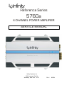
1
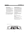
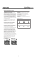
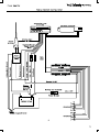
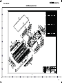
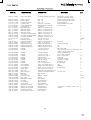
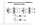
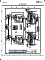
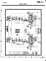
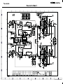
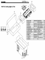
Reference Series
5760a
6 CHANNEL POWER AMPLIFIER
SERVICE MANUAL
Infinity Systems, Inc.
250 Crossways Park Dr.
Woodbury, New York 11797
Rev1
8/2004
Power Amplifier
Ref5760a
- CONTENTS SPECIFICATIONS ………………………………….……..1
FEATURES/TEST CONDITIONS……..…………………2
CONTROLS/CONNECTIONS………….……..…...…..…3
INSTALLATION………………….……...……..…...…...…5
BASIC TROUBLESHOOTING..…….…….………………8
TYPICAL SYSTEM WIRING..…….…….……………..…9
EXPLODED VIEW/PARTS LIST…………………..…....10
MECHANICAL PARTS LIST…………………………….11
AMPLIFIER BLOCK DIAGRAM…………………………12
P.C.B. DRAWINGS….…………………………………….13
ELECTRICAL PARTS LIST ……………………………. 17
IC/TRANSISTOR PINOUTS..……………………….. …..21
SCHEMATICS………..…………….……………………...24
PACKING…………………………….…………………….28
Reference 5760a Specifications
Output Power:
56W RMS x 4 and107W RMS x 2 channels @ 4 ohms; ≤1% THD + N
80W RMS x 4 and150W RMS x 2 channels @ 2 ohms; ≤1% THD + N
148W RMS x 2 and 287W RMS x 1 channels @ 4 ohms; ≤1% THD + N
Signal-to-noise ratio:
82dBA (reference 1W into 4 ohms)
Dynamic power:
117W channels 1,2,3,4; 163W channels 5,6 @ 2 ohms
Effective damping factor:
6.373 @ 4 ohms
Frequency response:
10Hz – 57kHz channels 1,2,3,4; 10Hz – 302Hz channels 5,6
Maximum input signal:
6.3V
Maximum sensitivity:
250mV
DC Offset
<50mV (-50%)
Output regulation:
.063dB @ 4 ohms
Idle Current
2.1A
Input Impedance
22kΩ
Max Current Draw
34A @ 4 ohms
88A @ 2 ohms
89.5 @ 4 ohm bridged
Dimensions:
12 x 18 1/2 x 2 11/16” (L x W x D)
(305mm x 470mm x 68mm)
Fuse:
2 x 30A
Infinity continually strives to update and improve existing products, as well as create new ones. The specifications and details in
this and related JBL publications are therefore subject to change without notice.
1
Power Amplifier
Ref5760a
Features
•
4-Channel Operation
•
Advanced MOSFET Oversized Floating Rail Power Supply
•
Floating Ground Factory - Head - Unit Speaker - Level input
•
Variable lnput Sensitivity (250mV - 6V)
•
Fully Complementary Output Stage with Class-A6 Voltage Amplification
•
Gold-plated Power, lnput and Output Connectors
•
2-Ohm Stable (Stereo)
Test Conditions and Notes
•
All tests to be done, unless otherwise specified, from 10Hz to 47KHz and 302Hz
at 14.4V DC into 4 ohm loads and adjust the units gain so that with a .775 volt
input signal the unit is at Its maximum rated output. All measurements will be
done using an Audio precision system one and the supply voltage.
•
An A+ line voltage of 14.4V DC shall be applied to the unit under test for all
measurements unless otherwise specified. The voltage applied to the unit shall
be measured at the power connection on the Amplifier.
•
Signal Source
Unless otherwise specified, all tests shall be conducted with the Audio Signal
Generator output configured to be balanced, less than or equal to 50 ohm source
impedance, and floating. The signal source "GND" shall be connected to the
Amplifier PWR GND at the Amplifier.
•
Output Load
Unless otherwise specified, all tests shall be conducted with 4 ohm resistive
loads having less than 10% reactive components at any frequency below 47KHz
and 302Hz. Each resistor shall have a value that remains within 1 % while
dissipating the rated output of the unit under test.
•
Power Indicator Green LED steadily illuminates for normal operation. Illuminates
up Red LED blinks when protection circuitry is engaged, and during power up.
2
Power Amplifier
Ref5760a
POWER CONNECTIONS
WIRE-GAUGE CHART
Amplifier
Maximum
Minimum
Model
Current Draw
Wire Gauge
7520a
34A
#8 AWG
7540a
85A
#8 AWG
5760a
87A
#8 AWG
310a
40A
#8 AWG
610a
69A
#6 AWG
1210a
115A
#4 AWG
These recommendations assume 7' – 10' wire
runs. If your installation differs markedly, you
will need to adjust the wire gauge accordingly.
The Reference amplifiers are capable of
delivering high power levels, and require a
reliable connection to the vehicle’s electrical
system in order to perform optimally. See
Figure 1 for connection location. Please
adhere to the following instructions carefully.
GROUND CONNECTION
Connect the amplifier’s Ground (GND) terminal
to a solid point on the vehicle’s metal chassis,
as close to the amplifier as possible. Refer to the
chart below to determine minimum wire-gauge
size. Sand away any paint from this location; use
a star-type-lock washer to secure the connection.
SPEAKER CONNECTIONS
Refer to the application guides on the pages
that follow. Speaker connections should be
made using a minimum of 16-gauge wire.
POWER CONNECTION
Connect a wire (see chart at right for appropriate
gauge) directly to the vehicle’s positive battery
terminal, and install an appropriate fuse holder
within 18" of the battery terminal. Do not
install the fuse at this time. Route the wire to
the amplifier’s location, and connect it to the
amplifier’s positive (+12V) terminal. Be sure to
use appropriate grommets whenever routing
wires through the firewall or other sheet metal.
Failure to adequately protect the positive wire
from potential damage may result in a vehicle
fire. When you are done routing and connecting
this wire to the battery and to the amplifier,
you may install the fuse at the battery. The
fuse value should be selected based on total
amplifier-current draw; see chart at right.
HIGH-LEVEL INPUT CONNECTIONS
The 7520a, 7540a and 5760a amplifiers are
equipped with speaker-level inputs that allow
you to add an amplifier to head units that do
not have RCA line outputs. The speaker outputs
for the source unit should be connected to the
amplifier using the supplied connector (square
four-wire plug). Remember to check for proper
polarity. The 310a, 610a and 1210a amplifiers
are not equipped with high-level inputs.
NOTE: When using the low-level or high-level
inputs, the AUX outputs can be used to pass a
full-range line-level signal to another amplifier.
REMOTE CONNECTION
Connect the amplifier’s Remote (REMOTE)
terminal to the source unit’s Remote Turn-On
lead using a minimum of 18-gauge wire. If your
source unit does not have a remote turn-on
connection, connect the amplifier’s (REMOTE)
terminal to the vehicle’s accessory circuit.
Figure 2. Speaker-level connector.
HIGH LEVEL
INPUT
–
L
+
–
R
+
GRAY +
GRAY/BLACK –
R L
Speaker Wires
(spliced)
Figure 1.Terminal-connection end plate.
•
2
– WHITE/BLACK
+ WHITE
If the amplifier’s fuse must be replaced, use
only the same type and rating as that of the
original. Do not substitute another kind.
3
5760a
Power Amplifier
Ref5760a
APPLICATIONS – 5760a
The 5760a can be configured for 6-channel,
5-channel or 3-channel operation, as shown
in Figures 10 through 12.
INPUT MODE SWITCH:
• Use INT (internal mode) to send a signal from
the front and rear inputs to the subwoofer.
• Use EXT (external mode) when sending a
dedicated signal to the subwoofer inputs; e.g.,
if your source unit has a subwoofer output.
NOTE: For simplicity, Figures 10 through 12 do
not show power, remote and input connections.
NOTE: Minimum speaker impedance for
stereo operation is 2 ohms. Minimum speaker
impedance for bridged operation is 4 ohms.
Figure 10. 6-Channel operation: 5760a amplifier driving full-range front and rear speakers and a pair of subwoofers.
Figure 11. 5-Channel operation: The same as Figure 10, with the subwoofer output bridged to drive a single 4-ohm subwoofer, providing
the speaker with more power.
Figure 12. 3-Channel operation: 5760a amplifier configured for 3-channel operation, where all of the channels are bridged for a
subwoofer and a pair of component speakers.
4
Power Amplifier
Ref5760a
INSTALLATION AND SETUP
SETTING THE CROSSOVER(S)
Determine your system plans and set the
crossover-mode switch accordingly. If your
system design does not include a subwoofer,
set the crossover mode to FLAT and skip to
“Setting Input Sensitivity.”
Initially set the crossover-frequency control
midway. While listening to music, adjust the
crossover for the least perceived distortion from
the speakers, allowing them to reproduce as
much bass as possible.
Systems using a separate subwoofer set the
crossover mode to HP (high pass) for your
full-range speakers. Adjust the crossover
frequency to limit bass, and provide increased
system volume with less distortion.
MODE SWITCH
Flat: Allows a full-range signal through to the
speakers; can be used with larger full-range
speakers such as 6" x 9"s.
HP: Allows a high-pass signal through to
the speakers; should be used with most
loudspeakers (can protect your full-range
speakers from being overdriven with low
frequencies, one cause of speaker damage).
LP: Allows bass to pass through to the speakers;
should be selected when powering subwoofers.
For subwoofers, choose the highest frequency
that removes vocal information from the sound
of the subwoofer.
If using the 7520a or 7540a to drive a subwoofer(s),
set the crossover mode to LP (low pass).
NOTE: The 310a, 610a, 1210a and the subwoofer
output of the 5760a are low-pass only and do not
have a crossover-mode switch.
Figure 13. Control end panel.
5760a
5760a
5
Power Amplifier
Ref5760a
SETTING INPUT SENSITIVITY
1. Initially turn the INPUT LEVEL control(s) to
minimum (counterclockwise).
2. Reconnect the (–) negative lead to the vehicle’s battery. Apply power to the audio system
and play a dynamic music track.
3. On the source unit, increase the volume
control to 3/4 volume. Slowly increase the
INPUT LEVEL control(s) toward three o’clock
until you hear slight distortion in the music.
Then reduce the INPUT LEVEL slightly until
distortion is no longer heard.
REMOTE LEVEL CONTROL (OPTIONAL)
All three Reference subwoofer amplifiers and
the 5760a amplifier have inputs for an optional
remote level control (100rc). This will allow the
subwoofer level to be adjusted from the listening
position. Connect the optional remote level
control using the RJ-11 jack on the side of the
amplifier. Install the control module in the front
of the vehicle within easy reach of the driver.
Both the underside of the dash and the center
console are suitable locations. Refer to the
mounting instructions accompanying the 100rc.
NOTE: After the source unit is on, blue LEDs (on
the top panel) will light, indicating the amplifier
is on. If not, check the wiring, especially the
remote connection from the source unit. Also
refer to “Troubleshooting” on the page 7.
SETTING THE BASS BOOST
The 7520a, 7540a and 5760a are all equipped
with a bass-boost control. This allows you to
enhance the bass output of your system at
50Hz up to 12dB.
NOTE: Only rear channels of the 7540a are
affected by the bass boost control.
AUX OUTPUT
Reference amplifiers (except 5760a) are equipped
with full-range outputs that can be used to
connect additional amplifiers.
NOTE: When using the low- or high-level inputs,
the AUX outputs can be used to pass a full-range
line-level signal to another amplifier.
Figure 13. Control end panel.
5760a
6
Power Amplifier
Ref5760a
INSTALLATION AND SETUP (CONT.)
SETTING DBO™ (310a, 610a and 1210a)
The Dynamic Bass Optimizer (DBO) is used to
enhance low-frequency reproduction in a vehicle.
Conventional bass-boost circuits only increase
bass at a fixed frequency, and cause the amplifier
to consume considerable power. The DBO allows
you to adjust the frequency (20Hz – 80Hz) as well
as the boost level (up to 12dB; see Figure 14),
allowing you to fine-tune the bass in your system
to optimize performance.
STATUS LEDs
Clip: Indicates the amplifier is being overdriven,
and your speakers may be in danger. This
should blink only on musical peaks, and not
be on constantly.
Power: Indicates the amplifier is on.
Protection: Refer to “Troubleshooting” for specific
indications.
Figure 15. LED status.
For sealed enclosures, the DBO can be used
to enhance the lower bass region of sealed
enclosures.
For bigger/fuller bass, adjust the HP FREQ
between 35Hz and 45Hz; adjust the BOOST
control according to your preference.
For tighter-sounding bass, adjust the HP FREQ
between 45Hz and 55Hz; adjust the BOOST
control according to your preference.
For vented enclosures, the DBO should be used
as a subsonic filter to reduce overexcursion
of the woofers. Set the HP FREQ control 10Hz
below the tuning frequency of the enclosure
(e.g., 25Hz for a box tuning of 35Hz); adjust the
BOOST control to taste. This will conserve
amplifier power typically wasted on frequencies
below the tuned frequency of the enclosure.
For infinite-baffle applications, set the HP FREQ to
the speaker’s Fs value (reducing overexcursion of
the woofer); adjust the Boost control to taste.
Figure 14. Frequency-response curves show
typical DBO control ranges.
DBO HP FREQ Control
HP FREQ
20Hz 100Hz
dB
DBO BOOST Control
12
-3
6
-6
0
-9
-6
20
80
Freq. (Hz)
MIN
dB
0
-12
BOOST
(adjusts boost amount
at cut-off frequency)
(adjusts cut-off
frequency)
-12
20
80
MAX
Freq. (Hz)
7
Power Amplifier
Ref5760a
TROUBLESHOOTING
• PROBLEM:
No audio (PROTECT LED is on).
• PROBLEM:
No audio (POWER LED is off).
CAUSE and SOLUTION:
Voltage greater than 16V or less than 8.5V on
BATT+ connection. Check vehicle charging
system.
CAUSE and SOLUTION:
No voltage at BATT+ and/or REM terminals, or
bad or no ground connection. Check voltages
at amplifier terminals with VOM.
• PROBLEM:
Distorted audio.
• PROBLEM:
No audio (PROTECT LED flashes every
4 seconds).
CAUSE and SOLUTION:
Input sensitivity is not set properly, or amplifier
or source unit is defective. Check INPUT LEVEL
setting, or check speaker wires for shorts or
grounds.
CAUSE and SOLUTION:
DC voltage on amplifier output. Amplifier may
need service; see enclosed warranty card for
service information.
• PROBLEM:
Distorted audio (PROTECT LED flashes).
• PROBLEM:
No audio (PROTECT LED is on).
CAUSE and SOLUTION:
Short circuit in speaker or wire. Remove
speaker leads one at a time to locate shorted
speaker or wire, then repair.
CAUSE and SOLUTION:
Amplifier is overheated. Make sure amplifier
cooling is not blocked at mounting location;
verify that speaker-system impedance is within
specified limits.
• PROBLEM:
Music lacks “punch.”
• PROBLEM:
No audio (PROTECT and POWER LEDs flash).
CAUSE and SOLUTION:
Speakers are not connected properly. Check
speaker connections for proper polarity.
CAUSE and SOLUTION:
Voltage less than 9V on BATT+ connection.
Check vehicle charging system.
8
9
A
B
C
D
E
10
1
2
3
4
5
6
7
8
HEA-01-184AA
HEAT SINK-MAIN
AL/EXTRUSION(L=470.0mm)
PAN-06-277AA
PAN-06-278AA
COV-06-110AA
COV-22-553AA
FOO-21-015AA
ILL-23-503A0
BKT-11-001A0
BKT-11-002A0
BKT-11-005A0
BKT-11-006A0
SUB-28-001A0
SUB-28-008A0
SUB-33-001A0
SIL-34-001A0
SS-5
SUP-02-0210
SUB-27-003A0
SUB-28-002A0
SUB-28-519A0
SUB-28-503A0
SC5-NB-30050
SC5-BB-30060
PANEL-FRONT
PANEL-REAR
COVER-BOTTOM
C OVER-LENS
FOOT-MOUNTING
ILLUMINATOR
BRACKET TR(A)
BRACKET TR(B)
BRACKET TR(C)
BRACKET TR(D)
CUSHION TR BRACKET(A)
CUSHION TR BRACKET(B)
CUSHION RUBBER
SILICON PAD
SUPPORT PCB(A)
SUPPORT-PCB(B)
SWITCH DECAL
PAPER SPACER(A)
PAPER SPACER(B)
PAPER SPACER(C)
SCREW
SCREW
EGI, 1.2t
EGI, 1.2t
EGI, 1.2t
ACRYLIC,(L=470mm)
ABS(XR-401),L=380mm
PC/MILKY
SBHG, 110.0x22.5x2.0t
SBHG, 110.0x25.5x2.0t
SBHG, 170.0x22.5x2.0t
SBHG, 170.0x25.5x2.0t
FIBER, 110.0x22.0x1.0t
FIBER, 170.0x22.0x1.0t
RUBBER, 10.0x20.0x1.6t
SP1000, 22.0x0.3t
NYLON, L=7.9mm
BSBM, L=29.0mm(NI-P)
FELT, 15.0x7.0x0.3t
FIBER, 200.0x6.0x0.5t
FIBER, 200.0x8.0x0.5t
FIBER, 200.0x10.0x0.5t
STT2 BH 3x5 NI-P
STT2 BH 3x6 BK
SC5-BB-30080
SC5-BP-30080
SC5-NB-30150
SC1-NB-30060
SC5-NP-35160
SC1-NL-40100
SC1-NP-40140
SC4-NO-40250
POL-31-185A0
POL-31-046A0
POL-31-003A0
INN-42-010A0
BOX-36-152AA
BOX-39-163AA
MAN-01-0197A
SUB-00-001A0
SUB-00-002A0
SUB-00-026A0
CAR-WA-0038A
LAB-MD-0001A
LAB-QC-0001A
LAB-CE-0004A
LAB-00-0427A
LAB-SR-0065A
LAB-SR-0066A
LAB-00-0424A
CAR-00-0061A
SCREW
SCREW
SCREW
SCREW
SCREW
SCREW
SCREW
SCREW
POLY BAG(A)
POLY BAG(B)
POLY BAG(C)
SNOW PAD
BOX-GIFT
BOX-CARTON
MANUAL
SILICAGEL
SCOTCH TAPE
OPP TAPE
WARRANTY CARD
STICKER
QC STICKER
CE STICKER
WINDOW STICKER
SERIAL NO STICKER
SERIAL NO STICKER
E-MARK STICKER
QUICK START GUIDE
STT2 BH 3x8 BK
STT2 PH 3x8 BK
STT2 BH 3x15 NI-P
SMB 3x6 NI-P
STT2 PH 3.5x16 NI-P
SML 4x10 NI-P
SMP 4x14 NI-P
STT1 OH 4x25 NI-P
VINYL, 650.0x400.0x0.1t
VINYL, 260.0x350.0x0.03t
VINYL, 120.0x120.0x0.03t
EPS, 363.0x160.0x128.0
SW#1(B), 620.0x368.0x133.0
DW#2, 635.0x286.0X393.0
ART PAPER
3g
WIDTH : 20mm
WHITE
ART PAPER
WHITE/BLACK
GOLD/BLACK
BLACK/WHITE
"INFINITY" LOGO
WHITE/BLACK
WHITE/BLACK
WHITE/BLACK
ART PAPER
11
side:P432C sandton spray
top:silver spray/silk screen
P432C Painting & silk screen
P432C Painting & silk screen
P432C Painting
SILKSCREEN,DUAL TAPE
SILVER SPRAY
1
1
1
1
1
2
1
2
2
2
2
2
2
7
600mm
10
SUB PCB
3
5
COVER-BOTTOM
4
TR
1
FET
1
GROUND WIRE
1
PANEL/S+H/S(8),SUB/P+ILLUMINATOR(2) 20
SUB/P+H/S(2),C/B+H/S(8)
RCA(3), TERMINAL(3)
6
R/P + FUSE HOLDER
1
PCB + HEAT SINK
10
SUB PCB
6
FOOT/M+ H/SINK
6
FOOT/M + H/SINK
8
BRACKET TR
12
ACCESSORY
4
1
SET
MANUAL
1
ACCESSORY
1
2
1
CLS-AM-4073
1/2
1
1
20cm
3.6m
1
1
1
1
1
"CODE 39" -> G/BOX, C/BOX, SET 3
1
H/SINK
1
1
Power Amplifier
Ref5760a
12
13
14
15
16
RES-00-00545
RES-00-00415
17
18
19
20
21
Power Amplifier
Ref5760a
22
23
A
B
C
D
E
1
2
3
4
5
24
6
7
8
A
B
C
D
E
1
2
3
5
4
25
6
7
8
A
B
C
D
E
1
2
3
4
5
26
6
7
8
A
B
C
D
E
1
2
3
4
27
5
6
7
8
Power Amplifier
Ref5760a
28