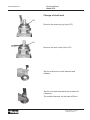
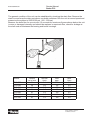
1
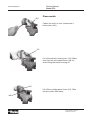
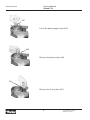
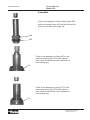
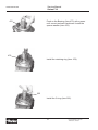
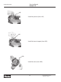
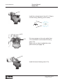
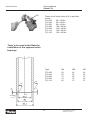
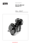
Bulletin HY30-5504-M1/UK
Service Manual
Series F12
Effective:
June, 2006
Supersedes: August, 2003
Service Manual
Series F12
HY30-5504-M1/UK
List of contents
Page
General information ...................................................................................3
Specifications ............................................................................................4
Disassembling ....................................................................................5 - 10
Assembling .......................................................................................11 - 16
Change of shaft seal ...............................................................................17
Valve plates .............................................................................................18
Conversion factors
1 kg
= 2.2046 lb
1N
= 0.22481 lbf
1 bar
= 14.504 psi
1l
= 0.21997 UK gallon
1l
= 0.26417 US gallon
1 cm3
= 0.061024 in3
1m
= 3.2808 feet
1 mm
= 0.03937 in
9/5 °C + 32 = °F
! WARNING
FAILURE OR IMPROPER SELECTION OR IMPROPER USE OF THE PRODUCTS AND/OR SYSTEMS DESCRIBED
HEREIN OR RELATED ITEMS CAN CAUSE DEATH, PERSONAL INJURY AND PROPERTY DAMAGE.
This document and other information from Parker Hannifin Corporation, its subsidiaries and authorized distributors provide
product and/or system options for further investigation by users having technical expertise. It is important that you analyze all
aspects of your application, including consequences of any failure, and review the information concerning the product or system in the current product catalogue. Due to the variety of operating conditions and applications for these products or systems,
the user, through its own analysis and testing, is solely responsible for making the final selection of the products and systems
and assuring that all performance, safety and warning requirements of the application are met.
The products described herein, including without limitation, product features, specifications, designs, availability and pricing, are
subject to change by Parker Hannifin Corporation and its subsidiaries at any time without notice.
Offer of Sale
Please contact your Parker representation for a detailed ”Offer of Sale”.
2
Parker Hannifin
Pump and Motor Division
Trollhättan, Sweden
Service Manual
Series F12
HY30-5504-M1/UK
General information
F12 is bent axis, fixed displacement heavyduty motor/pump seris. They can be used
in numerous applications in both open and
closed loop circuits.
The pump version has highly engineered
valve plates for increased selfpriming speed
and low noise, available with left and right
hand rotation.
Series F12 conforms to current ISO and
SAE mounting flange and shaft end configurations. A very compact cartridge version is
also available.
Frame sizes: F12-30, -40, -60, -80, -90,
-110 and -125.
The F12 motors produce very high torque
at start-up as well as at low speeds.
Thanks to the unique spherical piston design, F12 motors can be used at unusually
high shaft speeds. Operating pressures to
480 bar provides for the high output power
capability.
The 40° angle between shaft and cylinder
barrel allows for a very compact, lightweight
motor/pump.
The laminated piston ring offers important
advantages such as low internal leakage
and thermal shock resistance.
F12 cross section
1
2
Our unique timing gear design synchronizes
shaft and cylinder barrel, making the F12
very tolerant to high ’G’ forces and torsional
vibrations.
Heavy duty roller bearings permit substantial external axial and radial shaft loads.
The F12’s have a simple and straightforward design with very few moving parts,
making them very reliable motors/pumps.
The unique piston locking, timing gear and
bearing set-up as well as the limited number of parts add up to a very robust design
with long service life and, above all, proven
reliability.
3
4
5
6
7
8
9
1. Barrel housing
2. Valve plate
3. Cylinder barrel
4. Piston with piston ring
5. Timing gear
6. Tapered roller bearing
7. Bearing housing
8. Shaft seal
9. Output/input shaft
3
Parker Hannifin
Pump and Motor Division
Trollhättan, Sweden
Service Manual
Series F12
HY30-5504-M1/UK
Frame size
F12-030
F12-040
F12-060
F12-080
F12-090
F12-110
F12-125
30.0
40.0
59.8
80.4
93.0
110.1
125.0
max intermittent1) (bar)
480
480
480
480
420
480
480
max continuous (bar)
420
420
420
420
350
420
420
max intermittent1) (rpm)
7 300
6 700
5 800
5 300
5 000
4 800
4 600
max continuous (rpm)
6 700
6 100
5 300
4 800
4 600
4 400
4 200
min continuous (rpm)
50
50
50
50
50
50
50
3150
2870
2 500
2 300
2 250
2 290
2 100
max intermittent1) (l/min)
213
256
335
418
467
517
567
max continuous (l/min)
168
200
257
322
359
396
426
max (oC)
80
80
80
80
80
80
80
min ( C)
-40
-40
-40
-40
-40
-40
-40
1.7
2.9
5.0
8.4
8.4
11.2
11.2
12.0
16.5
21.0
26.0
26.0
36.0
36.0
Displacement (cm /rev)
3
Operating Pressure
Motor operating speed
Max pump sefpriming speed
2)
L or R function; max (rpm)
Motor input flow
Main circuit temp.
3)
o
Mass moment of inertia
(x10-3) (kg m2)
Weight
(kg)
1) Intemittent: max 6 seconds in any one minute.
2) Selfpriming speed valid at sea level.
3) See also below, operating temperature.
Operating temerature
The following temperatures should not be exceeded
(type H and N shaft seals):
Drain fluid: 90 oC.
FPM shaft seals (type E, type V) can be used to
115 oC drain fluid temperature.
NOTE: The temperature should be measured at
the utilized drain port.
Continuous operation may require case flushing in
order to meet the viscosity and temperature limitations.
For further information we refer to:
Catalgue HY17-8249/UK
4
Parker Hannifin
Pump and Motor Division
Trollhättan, Sweden
Service Manual
Series F12
HY30-5504-M1/UK
Disassemble
491
Fasten the unit in a vice. Loosen the 4
boults (item 491).
110
Lift off the barrel housing (item 110). Make
sure that the valve plate doesn’t fall out
when lifting the barrel housing off.
411
Lift off the cylinder barrel (item 411). Take
the shim (item 488) away.
488
5
Parker Hannifin
Pump and Motor Division
Trollhättan, Sweden
Service Manual
Series F12
HY30-5504-M1/UK
430
Lift off the barrel support (item 430).
440
Remove the pistons (item 440).
221
Remove the O-ring (item 221).
6
Parker Hannifin
Pump and Motor Division
Trollhättan, Sweden
Service Manual
Series F12
HY30-5504-M1/UK
237
Remove the retaining ring (item 237).
231
Remove the seal carrier (item 231).
225
Remove the O-ring (item 225).
7
Parker Hannifin
Pump and Motor Division
Trollhättan, Sweden
Service Manual
Series F12
HY30-5504-M1/UK
478
Remove the retaining ring (item 478).
476
Lift off the spacer washer (item 476).
311
211
Place the bearing housing (item 211) on a
tube.
Push out the shaft (item 311) with a press.
8
Parker Hannifin
Pump and Motor Division
Trollhättan, Sweden
Service Manual
Series F12
HY30-5504-M1/UK
470
Remove the small tappered roller bearing
(item 470).
Tap the small bearing ring off with a mandrel.
Tap the large bearing ring off with a mandrel.
9
Parker Hannifin
Pump and Motor Division
Trollhättan, Sweden
Service Manual
Series F12
HY30-5504-M1/UK
311
Tube
Place the ring gear (item 452) on a tube.
Push out the shaft (item 311) with a press.
452
10
Parker Hannifin
Pump and Motor Division
Trollhättan, Sweden
Service Manual
Series F12
HY30-5504-M1/UK
Assemble
Push on the tappered roller bearing (item 460)
and the ring gear (item 452) on the shaft with a
press. Use a tube (see page 16).
460
452
Push on the bearing ring (item 460) in the
bearing housing (item 211) with a press.
Use a tube to match the outer diameter off
the bearing ring.
211
Push on the bearing ring (item 470) in the
bearing housing (item 211) with a press.
Use a tube to match the outer diameter off
the bearing ring.
211
11
Parker Hannifin
Pump and Motor Division
Trollhättan, Sweden
Service Manual
Series F12
HY30-5504-M1/UK
476
Push on the Bearing (item 470) with a press
until correct preload is achieved. Install the
spacer washer (item 476).
478
Install the retaining ring (item 478).
225
Install the O-ring (item 225).
12
Parker Hannifin
Pump and Motor Division
Trollhättan, Sweden
Service Manual
Series F12
HY30-5504-M1/UK
Install the seal carrier (item 231).
231
237
Install the retaining ring (item 237).
221
Install the O-ring (item 221).
13
Parker Hannifin
Pump and Motor Division
Trollhättan, Sweden
Service Manual
Series F12
HY30-5504-M1/UK
440
Install the pistons (item 440).
430
Install the barrel support (item 430).
488
Install the shim (item 488).
14
Parker Hannifin
Pump and Motor Division
Trollhättan, Sweden
Service Manual
Series F12
HY30-5504-M1/UK
411
Install the cylinder barrel (item 411). Ensure
correct timing. (Marking, punch mark)
.
. .
121
110
Put some grease on the valve plate (item
121) and install it into the barrel housing
(item 110).
Make sure you have installed the valve
plate correct (see page 18).
110
Install the barrel housing (item 110).
15
Parker Hannifin
Pump and Motor Division
Trollhättan, Sweden
Service Manual
Series F12
HY30-5504-M1/UK
491
Fasten the 4 boults (item 491) to specified
torque.
F12-030
60 ± 10 Nm
F12-040
60 ± 10 Nm
F12-060
60 ± 10 Nm
F12-080
105 ± 20 Nm
F12-090
105 ± 20 Nm
F12-110
105 ± 20 Nm
F12-125
105 ± 20 Nm
Tools to be used to facilitate the
installation of the tappered roller
bearings.
30°
Type
ØA
ØB
ØC
F12-030
F12-040
F12-060
F12-080
F12-110
60
65
73
74
82
49
58
64
70
75
42
52
57
62
67
0.5×45°
3
1.5
30°
+0.2
ØC 0
ØB
0
ØA -1
16
Parker Hannifin
Pump and Motor Division
Trollhättan, Sweden
Service Manual
Series F12
HY30-5504-M1/UK
Change of shaft seal
237
Remove the retaining ring (item 237).
231
Remove the seal carrier (item 231).
Tap the shaft seal out with hammer and
mandrel.
Tap the new shaft seal back with a tube and
a hammer.
The outside diameter on the tube is 65mm.
17
Parker Hannifin
Pump and Motor Division
Trollhättan, Sweden
Service Manual
Series F12
HY30-5504-M1/UK
Valve plates F12
Following valve plates can be fitted in F12.
M
M = Bi-directional, motor operation
Against cylinder barrel
L
R
L = L.H. rotation, pump operation
R = R.H. rotation, pump operation
Against cylinder barrel
G
G = L.H. rotation, internal drain, motor
operation
X
X = Bi-directional, pump operation, high self
priming speed
Against cylinder barrel
18
Parker Hannifin
Pump and Motor Division
Trollhättan, Sweden
Service Manual
Series F12
HY30-5504-M1/UK
The general condition of the unit can be established by checking the drain flow. Remove the
drain line and keep the drain port above a suitable container. Run the unit at normal speed and
pressurize the system to 2000-3000 psi. (150 - 200 bar)
Measure the drain flow for one minute; if it exceeds the maximum figures shown below, the unit
is worn or damaged internally and should be replaced or repaired. Also, check for leakage at
the shaft seal and between the bearing and barrel housings.
Series
F12-030
F12-040
F12-060
F12-080
F12-090
F12-110
F12-125
Normal
cu.in./min
24
30
43
61
61
61
61
Normal
l/min
0.4
0.5
0.7
1.0
1.0
1.0
1.0
19
Max
gpm.
.55
.65
.70
.80
.80
.80
.80
Max
l/min
2.0
2.5
2.7
3.0
3.0
3.0
3.0
Parker Hannifin
Pump and Motor Division
Trollhättan, Sweden
Parker Hannifin
Pump and Motor Division
Flygmotorvägen 2
SE-461 82 Trollhättan
Sweden
Tel: +46 (0)520 40 45 00
Fax: +46 (0)520 371 05
www.parker.com