1
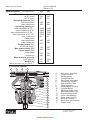
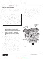
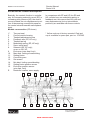
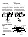
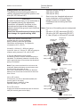
Bulletin HY30-5510-M1/UK
Service Manual
Series V14
Effective:
May 2012
Supersedes: February 2012
www.comoso.com
Service Manual
Series V14
Bulletin HY30-5510-M1/UK
List of contents
Page
New features V14....................................................................................... 3
Specifications / cross section..................................................................... 4
Displacement limiter..............................................................................5 - 6
Ordering code............................................................................................. 7
Installation.............................................................................................8 - 9
Controls and gauge ports..................................................................10 - 16
Displacement limiter................................................................................. 17
Disassembling...................................................................................18 - 23
Assembling........................................................................................24 - 30
Control spring kit and filter........................................................................ 31
Spare parts........................................................................................32 - 34
Split views.........................................................................................35 - 41
Spare parts............................................................................................... 42
Test procedure.......................................................................................... 43
Conversion factors
1 kg
1 N
1 bar
1 l
1 l
1 cm3
1 m
1 mm
1°C !
= 2.2046 lb
= 0.22481 lbf
= 14.504 psi
= 0.21997 UK gallon
= 0.26417 US gallon
= 0.061024 in3
= 3.2808 feet
= 0.03937 in
= 1.8°F + 32
WARNING
FAILURE OR IMPROPER SELECTION OR IMPROPER USE OF THE PRODUCTS AND/OR SYSTEMS DESCRIBED
HEREIN OR RELATED ITEMS CAN CAUSE DEATH, PERSONAL INJURY AND PROPERTY DAMAGE.
This document and other information from Parker Hannifin Corporation, its subsidiaries and authorized distributors provide
product and/or system options for further investigation by users having technical expertise. It is important that you analyze all
aspects of your application, including consequences of any failure, and review the information concerning the product or system in the current product catalogue. Due to the variety of operating conditions and applications for these products or systems,
the user, through its own analysis and testing, is solely responsible for making the final selection of the products and systems
and assuring that all performance, safety and warning requirements of the application are met.
The products described herein, including without limitation, product features, specifications, designs, availability and pricing,
are subject to change by Parker Hannifin Corporation and its subsidiaries at any time without notice.
Offer of Sale
Please contact your Parker representation for a detailed ”Offer of Sale”.
2
www.comoso.com
Parker Hannifin
Pump and Motor Division
Trollhättan, Sweden
Service Manual
Series V14
Bulletin HY30-5510-M1/UK
General information
Important features carried over
from previous motors:
Series V14 is a new generation of variable
displacement motors developed and manufactured by Parker Hannifin, Pump and
Motor Division.
The V14 is a further development of our
well known V12 motor. It is designed for
both open and closed circuits, intended
particularly for mobile applications.
New features:
• Increased shaft speeds
•
Improved sealing
• Faster control response
•
Improved shaft support
• Additional integrated functions added
• New control, HPC, for winch
•
Operating pressures to 480 bar
• High speeds, thanks to low weight pistons with laminated piston rings and a very compact design of the rotating parts.
•
High overall efficiency throughout the entire displacement range
•
9 pistons provide high start-up
torque and smooth operation
•
Wide displacement range - 5:1
•
Small envelope size and high
power-to-weight ratio
•
Low noise levels due to the compact, sturdy design and smooth fluid passages
•
...mainly thanks to:
• Re-designed piston
•
O-ring seals between housings
• Enlarged setting piston
•
Increased size control device
•
Tapered roller bearings
Positive piston locking, strong synchronizing shaft, heavy-duty bearings and a small number
of parts add up to a very robust
motor with long service life and
proven reliability.
3
www.comoso.com
Parker Hannifin
Pump and Motor Division
Trollhättan, Sweden
Service Manual
Series V14
Bulletin HY30-5510-M1/UK
Specifications V14 frame size
Displacement [cm³/rev]
at 35° (max)
at 6,5° (min)
Operating pressure [bar]
max intermittent
max continuous
Operating speed [rpm]
max intermittent at 35° ¹)
max continuous at 35°
max intermittent at 6.5°-20° ¹)
max continuous at 6.5°-20°
min continuous
Flow [l/min]
max intermittent
max continuous
Output torque [Nm]
at 100 bar (theor.)
Max output power [kW]
Corner power [kW]
intermittent
continuous
Mass moment of inertia
(x10-3) [kg m2]
Weight [kg]
110
110
22
160
160
32
480
420
480
420
3900
3400
6500
5700
50
3400
3000
5700
5000
50
430
375
550
480
175
262
255
335
570
440
730
560
8.2
54
14.5
68
¹) Max 6 seconds in any one minute.
V14 cross section
1
2
3
4
5
6
7
8
9
10
11
12
13
14
15
1. 2. 3. 4. 5. 6. 7. 8. 9.
10.
11.
12.
13.
14.
15.
16.
17.
End cover, min displ.
Control module
Setting piston
Connecting arm
End cover, max displ.
Connection module
Main pressure port
Valve segment
Intermediate housing
Cylinder Barrel
Spherical piston with
laminated piston ring
Synchronizing shaft
Inner roller bearing
Outer roller bearing
Bearing housing
Shaft seal with retainer
Output shaft
16
17
4
www.comoso.com
Parker Hannifin
Pump and Motor Division
Trollhättan, Sweden
Service Manual
Series V14
Bulletin HY30-5510-M1/UK
Displacement limiter V14-110
Setting
angle
[degree]
Displacement
[cm³/varv]
Shim
maximum
side
[mm]
6,5
6,9
7,2
7,5
7,8
8,1
8,4
8,7
9,0
9,3
9,6
9,9
10,2
10,5
10,8
11,1
11,4
11,7
12,0
12,3
12,7
13,0
13,3
13,6
13,9
14,2
14,5
14,8
15,1
15,4
15,7
16,0
16,4
16,7
17,0
17,3
17,6
17,9
18,2
18,5
18,9
19,2
19,5
19,8
20,1
22
23
24
25
26
27
28
29
30
31
32
33
34
35
36
37
38
39
40
41
42
43
44
45
46
47
48
49
50
51
52
53
54
55
56
57
58
59
60
61
62
63
64
65
66
58,5
58,0
57,5
57,0
56,0
55,5
55,0
54,5
54,0
53,5
53,0
52,5
52,0
51,5
51,0
50,0
49,5
49,0
48,5
48,0
47,5
46,5
46,0
45,5
45,0
44,5
44,0
43,0
42,5
42,0
41,5
41,0
40,5
40,0
39,0
38,5
38,0
37,0
36,5
35,5
35,5
34,5
34,0
33,5
33,0
Shim minimum side
[mm]
Setting
angle
[degree]
9,5
10,0
10,5
11,0
11,5
12,0
12,5
13,0
13,5
14,0
15,0
15,5
16,0
16,5
17,0
17,5
18,0
18,5
19,0
20,0
20,5
21,0
21,5
22,0
22,5
23,0
24,0
24,5
25,0
25,5
26,0
27,0
27,5
28,0
28,5
29,0
30,0
30,5
31,0
32,5
32,5
33,0
33,5
34,0
35,0
20,4
20,8
21,1
21,4
21,7
22,1
22,4
22,7
23,0
23,3
23,7
24,0
24,3
24,7
25,0
25,3
25,6
26,0
26,3
26,6
27,0
27,3
27,7
28,0
28,3
28,7
29,0
29,4
29,7
30,0
30,4
30,7
31,1
31,4
31,8
32,1
32,5
32,8
33,2
33,6
33,9
34,3
34,5
34,5
Displacement
[cm³/varv]
Shim
maximum
side
[mm]
Shim minimum side
[mm]
67
68
69
70
71
72
73
74
75
76
77
78
79
80
81
82
83
84
85
86
87
88
89
90
91
92
93
94
95
96
97
98
99
100
101
102
103
104
105
106
107
108
109
110
32,0
31,5
31,0
30,0
29,5
29,0
28,0
27,5
27,0
26,0
25,5
25,0
24,0
23,5
23,0
22,0
21,0
20,5
20,0
19,0
18,5
17,5
17,0
16,0
15,0
14,5
13,5
13,0
12,0
11,0
10,5
9,5
9,0
8,0
7,0
6,0
5,5
4,5
3,5
2,5
1,5
0,5
0,0
0,0
35,5
36,0
37,0
37,5
38,0
39,0
39,5
40,0
41,0
41,5
42,0
43,0
43,5
44,5
45,0
45,5
46,5
47,0
48,0
48,5
49,5
50,0
51,0
51,5
52,5
53,0
54,0
55,0
55,5
56,5
57,5
58,0
59,0
60,0
60,5
61,5
62,5
63,5
64,0
65,0
66,0
67,0
68,0
69,0
Note! There always have to be a shim on the minimum side of the -110cc motor. (9 mm)
The -110cc motor will be damaged if set below angles of 6,5°.
5
www.comoso.com
Parker Hannifin
Pump and Motor Division
Trollhättan, Sweden
Service Manual
Series V14
Bulletin HY30-5510-M1/UK
Displacement limiter V14-160
Setting
angle
[degree]
6,5
6,6
6,8
7,0
7,2
7,4
7,6
7,8
8,0
8,2
8,4
8,7
8,9
9,1
9,3
9,5
9,7
9,9
10,1
10,3
10,5
10,7
10,9
11,2
11,4
11,6
11,8
12,0
12,2
12,4
12,6
12,8
13,0
13,3
13,5
13,7
13,9
14,1
14,3
14,5
14,7
14,9
15,2
15,4
15,6
15,8
16,0
16,2
16,4
16,6
16,9
17,1
17,3
17,5
17,7
17,9
18,2
18,4
18,6
18,8
19,0
19,2
19,5
19,7
19,9
Displacement
[cm³/varv]
31,6
32
33
34
35
36
37
38
39
40
41
42
43
44
45
46
47
48
49
50
51
52
53
54
55
56
57
58
59
60
61
62
63
64
65
66
67
68
69
70
71
72
73
74
75
76
77
78
79
80
81
82
83
84
85
86
87
88
89
90
91
92
93
94
95
Shim
maximum
side
[mm]
69,5
69,0
68,5
68,0
67,5
67,5
67,0
66,5
66,0
65,5
65,0
64,5
64,0
64,0
63,5
63,0
62,5
62,0
61,5
61,0
60,5
60,0
60,0
59,5
59,0
58,5
58,0
57,5
57,0
56,5
56,0
56,0
55,5
55,0
54,5
54,0
53,5
53,0
52,5
52,0
51,5
51,0
50,5
50,0
49,5
49,0
49,0
48,5
48,0
47,5
47,0
46,5
46,0
45,5
45,0
44,5
44,0
43,5
43,0
42,5
42,0
41,5
41,0
40,5
40,0
Shim minimum side
[mm]
Setting
angle
[degree]
0,0
0,0
0,5
1,0
1,5
2,0
2,5
3,0
3,0
3,5
4,0
4,5
5,0
5,5
6,0
6,5
6,5
7,0
7,5
8,0
8,5
9,0
9,5
10,0
10,0
11,0
11,0
11,5
12,0
12,5
13,0
13,5
14,0
14,5
15,0
15,5
15,0
16,0
16,5
17,0
17,5
18,0
18,5
19,0
19,5
20,0
20,5
21,0
21,5
22,0
22,5
23,0
23,5
24,0
24,5
25,0
25,5
26,0
26,0
26,5
27,0
27,5
28,0
28,5
29,0
20,1
20,3
20,5
20,8
21,0
21,2
21,4
21,6
21,9
22,1
22,3
22,5
22,8
23,0
23,2
23,4
23,6
23,9
24,1
24,3
24,5
24,8
25,0
25,2
25,5
25,7
25,9
26,1
26,4
26,6
26,8
27,1
27,3
27,5
27,7
28,0
28,2
28,4
28,7
28,9
29,1
29,4
29,6
29,9
30,1
30,3
30,6
30,8
31,0
31,3
31,5
31,8
32,0
32,3
32,5
32,7
33,0
33,2
33,5
33,7
34,0
34,2
34,5
34,7
35,0
6
www.comoso.com
Displacement
[cm³/varv]
Shim
maximum
side
[mm]
Shim minimum side
[mm]
96
97
98
99
100
101
102
103
104
105
106
107
108
109
110
111
112
113
114
115
116
117
118
119
120
121
122
123
124
125
126
127
128
129
130
131
132
133
134
135
136
137
138
139
140
141
142
143
144
145
146
147
148
149
150
151
152
153
154
155
156
157
158
159
160
39,5
39,0
38,5
38,0
37,5
37,0
36,5
36,0
35,5
35,0
34,5
34,0
33,0
32,5
32,0
31,5
31,0
30,5
30,0
29,5
29,0
28,0
27,5
27,0
26,5
26,0
25,5
25,0
24,0
23,5
23,0
22,5
22,0
21,0
20,5
20,0
19,5
18,5
18,0
17,5
17,0
16,0
15,5
15,0
14,0
13,5
13,0
12,0
11,5
11,0
10,0
9,5
9,0
8,0
7,5
7,0
6,0
5,5
4,5
4,0
3,0
2,5
1,5
1,0
0,0
30,0
30,5
31,0
31,5
32,0
32,5
33,0
33,5
34,0
34,5
35,0
35,5
36,0
36,5
37,0
37,5
38,0
39,0
39,5
40,0
40,5
41,0
41,5
42,0
42,5
43,5
44,0
44,5
45,0
45,5
46,0
47,0
47,5
48,0
48,5
49,5
50,0
50,5
51,0
52,0
52,5
53,0
53,5
54,5
55,0
55,5
56,5
57,0
57,5
58,5
59,0
59,5
60,5
61,0
62,0
62,5
63,0
64,0
64,5
65,5
66,0
67,0
67,5
68,5
69,0
Parker Hannifin
Pump and Motor Division
Trollhättan, Sweden
Service Manual
Series V14
Bulletin HY30-5510-M1/UK
Ordering code
Example: V14 - 110 - S V S - EP I 1 A - P 350 - N - 00 - 110 / 032 - 210 - 000
1
2 3 4
5 6 7 8
9 10
11
12
13
14
15
16
8. Control modulating pressure/current
1. Frame size
N - AC, AD: 0 bar; EP: non-selectable 110 - 110 cm³/rev
current
160 - 160 cm³/rev
A - 15 bar1) (AC, AD, AH, HP)
2. Mounting flange
B - 25 bar1) (AC, AD, AH, HP)
C - Cartridge (Cartridge version only -110)
C - 50 bar1) (AC, AD, AH)
I - ISO (ISO 3019/2)
D - 80 bar1) (AC, AD, AH)
Z - ZF (ISO 3019/2)
9. Valve options
S - SAE (SAE J744c)
N - None
3. Shaft seal
B - Brake valve and pressure relief valves
V - FPM (fluorocarbon)
L - Flushing valve
4. Shaft end
P - Pressure relief valves
C - DIN (ISO version)
R - Optional valves
D - DIN (ISO version)
W - Load holding valve
S - SAE (SAE version)
10. Pressure relief valve opening pressure [bar] 5. Control
or Flushing valve restrictor. See catalogue AC - Pressure compensator
HY30-8223/UK for further information.
AH - Pressure compensator with
000 - Without Pressure relief valves
hydraulic override
11. Sensor options
AD - Pressure compensator with electric N - None
override and break defeat
C - Prepared for setting piston position EO - Electrohydraulic, two position
and shaft speed sensors
EP - Electrohydraulic, proportional
D - Speed and setting piston position HO - Hydraulic, two-position
sensors
HP - Hydraulic, proportional
L - Setting piston position sensor
6. Control signal
P - Prepared for speed sensor
E - External pressure (HO, HP) T - Prepared for setting piston position H - 24 VDC (EO, EP)
sensor
L - 12 VDC (EO, EP)
12. Factory issued number for special versions
I - Internal pressure (AC, AD, AH)
13. Max displacement [cm3/rev]
C - Pressure cut off (HP)
14. Min displacement [cm3/rev]
7. Control restrictor set
1 - 0,715. Threshold setting
AC: select pressure between 100 and 350 2 - 0,8
[bar]
3 - 1,0 (standard)
EO,EP: 12 VDC: 400 [mA]
4 - 1,2
24 VDC: 200 [mA]
5 - HPC
HO,HP: Factory set at 10 [bar]
x - special
Is adjustable between 5 - 25 [bar]
16. Setting for pressure cut off (only HPC control)
HPC: Select cut off pressure between
75 - 400 [bar]
1)
Valid at max utilized displacement range
7
www.comoso.com
Parker Hannifin
Pump and Motor Division
Trollhättan, Sweden
Service Manual
Series V14
Bulletin HY30-5510-M1/UK
Motor installation
Direction of rotation
Port A
The V14 motor is bi-directional. Fig. 1
shows shaft rotation vs. direction of flow.
When the A port is pressurized (black arrow) the motor turns counter clockwise (left
hand, L, rotation), and when the B port is
pressurized (open arrow) the shaft turns
clockwise (right hand, R, rotation).
Note: Before installing the V14 in series
(when the A and B ports can be subject to
high pressures simultaneously) contact Parker Hannifin (Mobile Controls Div.).
Filtration
Maximum motor service life is obtained
when the fluid cleanliness meets or exceeds ISO code 18/13 (ISO 4406).
A 10 µm (absolute) filter is recommended.
Case pressure
The lowest and highest recommended case
pressure (V14 with shaft seal type H or V)
at selected shaft speeds is shown in the
table below.
The min case pressure secures sufficient
lubrication, and the max case pressure,
which secures nominal seal life, should be
measured at the drain port.
Size
1500 3000 4000 5000 6000
max 10 1-6 1.5-5 2-4.5 V14-110
max 10 1-6 2-5.5 2.5-5.5 V14-160
Min and max case pressure [bar] vs. shaft speed
[rpm].
Note: Contact Parker Hannifin (Pump and
Motor Div.) for information on other shaft
seals.
Port B
Left hand
(counter clockwise)
rotation (L)
Right hand
(clockwise)
rotation (R)
Fig. 1 (motor rotation vs. direction of flow).
Required inlet pressure
The motor operates as a pump under certain conditions. When this occurs, a minimum pressure must be maintained at the
inlet port. Increased noise and gradually
deteriorating performance due to cavitation
may otherwise be experienced.
A 15 bar inlet pressure, measured at the
motor inlet port, satisfies most operating
conditions.
Contact Parker Hannifin (Mobile Controls
Div.) for more specific information on inlet
pressure requirements.
Note: For high speed info, see Marketing
information database.
Operating temperatures
The following temperatures should not be
exceeded (type H shaft seal):
Main circuit: 80 °C
Drain fluid: 100 °C
FPM shaft seals (type V) can be used to
115 °C drain fluid temperature.
Continuous operation at high power levels
usually requires case flushing in order for
the fluid to stay above the minimum viscosity requirements.
A flushing valve and restricting nozzle, available as an option, provide the necessary
main circuit flushing flow.
Refer to fig. 2 (next page).
8
www.comoso.com
Parker Hannifin
Pump and Motor Division
Trollhättan, Sweden
Service Manual
Series V14
Bulletin HY30-5510-M1/UK
Drain ports
There are two drain ports on the V14; the
uppermost drain port should always be
utilized (fig. 3).
In order to avoid excessively high case
pressure, the drain line should be connected directly to the reservoir.
Note:
A drain line spring loaded check valve (shown in
fig. 2, 3 and 4) may have to be installed in order to
prevent oil from being siphoned out of the motor
case. This can otherwise happen e.g. if the reservoir is located below the utilized motor drain port.
NOTE: When the motor is operating, the
case must be filled with fluid to at least
50%.
Flushing valve
(optional)
Hydraulic fluids
Ratings and performance data for series
V14 motors are valid when a good quality,
contamination-free, petroleum-based fluid is
used in the hydraulic system.
Hydraulic fluids type HLP (DIN 51524),
automatic transmission fluids type A, or API
CD engine oils can be used.
Drain and
cooling flow
to reservoir
Check valve
Fig. 2.
Fire resistant fluids, when used under modified operating conditions, and synthetic
fluids are also suitable.
To reservoir
Check valve
When the hydraulic system has reached full
operating temperature, the motor drain oil
viscosity should be above 8 mm²/s (cSt).
Drain port
At start-up, the viscosity should not exceed
1500 mm²/s.
Fig. 3.
The ideal operating range for the V14
series is 15 to 30 mm²/s.
Drain port
The following information (available from
Parker Hannifin, Pump and Motor Div.) provide additional information about:
- Hydraulic fluid specifications
- Fire resistant fluids
Check
valve
Before start-up
Make sure the motor case as well as the
entire hydraulic system is filled with hydraulic fluid. The internal leakage, especially at
low operating pressures, is not sufficient to provide lubrication at start-up.
Fig. 4.
To reservoir
9
www.comoso.com
Parker Hannifin
Pump and Motor Division
Trollhättan, Sweden
Service Manual
Series V14
Bulletin HY30-5510-M1/UK
Controls - general information
The displacement angle (between output
shaft and cylinder barrel) ranges from 35°
(max) to 6.5° (min).
Servo supply pressure is obtained from the
pressurized, main port through the corresponding, built-in shuttle valve.
The respons time (i.e. from max-to-min or
from min-to-max displacement) is determined
by restrictors in the servo valve supply and
return lines; refer to the schematics.
The following controls satisfy most application
requirements:
• AC (automatic pressure compensator)
• AD (Automatic pressure compensator with electric override and brake defeat)
• AH (automatic pressure compensator with hydraulic override)
• EO and HO (two position controls)
• EP and HP (proportional controls)
All controls utilize a servo piston that connects to the valve segment (refer to the illustration on page 4).
The built-in four-way servo valve determines
the position of the servo piston and, in turn,
the displacement.
AC control description
1. 2. 3. 4. 5. 6. 7. 8*. 9. 10. 11. 12. 13. 14. 15. 16. E.
8
7
6
5
4
3
2
1
1
AC control cover
E
E
Servo valve spool
Modulating spring
Threshold spring
Feedback arm
Threshold adjustment screw
Seal nut
Two-part threshold seal
End cover (max displ.)
Control module housing
Max displ. limiting screw/bushing
Set screws
9
10
9
16
15
14
13
12
11
Connecting arm
Setting piston
Min displ. limiting screw/bushing
End cover (min displ.)
Restrictor location, servo supply
2
3
4
5
6
7
8
10
11
12
13
14
15
16
V14_AC_section.eps
AC control module cross section (as seen
from motor
A./01-03-12
intermediate housing / control moduleLeif
interface).
* Yellow seal cap is factory mounted. Red seal cap is available as spare part, part no. 3797065.
10
www.comoso.com
Parker Hannifin
Pump and Motor Division
Trollhättan, Sweden
Service Manual
Series V14
Bulletin HY30-5510-M1/UK
AC control function
Refer to the illustration below left:
When pressure in port A (or B) increases,
the servo valve spool is pushed to the
right, directing flow to the right hand setting
chamber - the setting spool moves to the
left; displacement and output torque increases. At the same time, the shaft speed
decreases correspondingly (at a constant
pump flow to the motor).
Refer to the illustration below right:
When pressure in port A (or B) decreases,
the servo valve spool moves to the left, directing flow to the left hand setting chamber
- the setting spool moves to the right; displacement and output torque decreases.
At the same time, the shaft speed increases
correspondingly (at a constant pump flow to
the motor).
A
A
E
E
D
B
B
C
C
35
D
6,5
6,5
Min
Min
35
Max
Max
AC control function (displ. increase at increasing
V14_AC_function_1.eps ny
pressure).
Leif A./01-04-03
AC control function (displ. decrease
at decreasing
V14_AC_function_2.eps
ny
pressure).
Leif A./01-04-003
AC port and restrictor locations
Port connections and restrictor posiO-ring groove
D
C
B
A
Facing
motor
A housing
B
C
tions (AC control)
A. Port A connection
B. Port B connection
C. Restrictor position, min-to-max servo pressure (M5)
D.
Restrictor location, max-to-min
servo pressure (M5)
E.
Restrictor location, servo supply
(refer to cross section page 9)
D
O-ring
Facing motor
V14_AC_module.eps
Leif A./01-03-12
11
www.comoso.com
Parker Hannifin
Pump and Motor Division
Trollhättan, Sweden
Service Manual
Series V14
Bulletin HY30-5510-M1/UK
Gauge ports AC/AD/AH control
Pressure setting procedure
The pressure setting procedure is valid for
all pressure compensators (AC, AD and
AH).
5.
Start to turn the threshold adjustment screw clockwise until the pressure in gauge X2 starts to increase. Right threshold pressure setting has been reached.
WARNING
In order to prevent injury to the technician or
the bystanders during the adjustment
procedure, all hydraulic functions on the
vehicle/machine should be disabled (e.g.
wheels raised off the ground, work functions
disconnected).
Avoid fast forward/reversed changes that
can damage the synchronizing shaft.
1. Make sure that the motor has been supplied with the correct modulating spring (ordering code and name
plate information should correspond).
2.
Install 0 - 600 bar (0 - 8500 psi)
gauges in port X1 and X5; refer to fig. 1.
3.
Turn the adjustment screw counter clockwise to ensure that the thres-
hold spring is unloaded.
The distance between nut and screw end is approximately 23 mm when the threshold spring is unloaded.
Note: One turn of the setting screw corresponds to 57 bar (820 psi).
Port X4
Port X5
Gauge port
X2 (min)
Main port A
Main port B
Note! The distance between nut and screw
end should not be more than 28 mm, because of risk for loosing guiding of the spring.
4.
Gauge port
X1 (max)
fig. 1
Increase the system pressure (e.g. by blocking the motor shaft) to desi
red pressure setting (read the pres
sure in port X5).
12
www.comoso.com
Parker Hannifin
Pump and Motor Division
Trollhättan, Sweden
Service Manual
Series V14
Bulletin HY30-5510-M1/UK
EO/EP/HO/HP control description
Basically, the controls function in a similar
way. At increasing solenoid current (EP) or
increasing pilot pressure (HP) the control
moves towards the min displacement position. At decreasing current/pilot pressure,
the control retracts towards max displacement.
Module cross section (EP shown)
In comparison with EP and HP, the EO and
HO controls have no modulating spring or
feedback arm; this means that only min and
max displacements (but no intermediate
positions) are available with these controls.
1*.
2.
3.
4.
5.
6.
7.
8.
9.
10.
11.
12.
13.
14.
15.
16.
E.
* Yellow seal cap is factory mounted. Red seal
cap is available as spare part, part no. 3797065.
Two-part seal
Control module housing
Treshold adjustment screw
Feedback arm (EP, HP only)
Treshold spring
Modulating spring (EP, HP only)
Servo valve spool
Solenoid (EO, EP only);
cover on HO, HP
End cover (max displ. limit)
Max displ. limiting screw/bushing
Setting piston
Connecting arm
Set screws
Min displ. limiting screw/bushing
Setting piston position sensor
End cover position sensor
(min displ. limit)
Restrictor location, servo supply
2
1
3
5
4
6
7
8
E
9
10
11
13
12
13
www.comoso.com
14
15
16
Parker Hannifin
Pump and Motor Division
Trollhättan, Sweden
Service Manual
Series V14
Bulletin HY30-5510-M1/UK
HP control function
EP control function
(decreasing pilot pressure)
Refer to the illustration below right:
When the pilot pressure decreases, the pilot
piston retracts, the servo valve spool moves
to the right and flow is directed to the right
hand setting chamber - the setting spool
moves to the left and the displacement increases.
The shaft speed now decreases and the
available output torque increases corres-pondingly (at a constant pump flow and system
pressure).
(solenoid current increasing)
Refer to the illustration below left:
At an increasing current (above the threshold
value), the solenoid spool pushes left on the
servo valve spool, and flow is directed to the
left hand setting chamber - the setting spool
moves to the right and the displacement decreases.
This means, that the shaft speed increases
while the output torque decreases correspondingly (at a constant pump flow and system
pressure).
A
A
Solenoid
D
B
Pilot
port X5
E
D
B
C
C
6,5
6,5
35
E
35
Min
Min
Max
Max
EP control function (displ. decrease at increasing
V14_EP_function_1.eps ny
current).
HP control function (displ. increase at decreasing
V14_HP_function.eps
pilot pressure).
Leif A./01-04-03
EO/EP/HO/HP port and restrictor
locations
Leif A./01-04-04
A
B
Oacing
B
A
F
D
C
-ring groove
motor housing
O-ring
D
C
Facing motor
Port connections and restrictor positions (EP control)
A.
B.
C.
D.
E.
Port A connection
Port B connection
Restrictor position, max-to-min
servo pressure
Restrictor position, min-to-max
servo pressure
Restrictor location, servo supply
(refer to cross section page 12)
V14_EP_module.eps
14
www.comoso.com
Leif A./01-03-13
Parker Hannifin
Pump and Motor Division
Trollhättan, Sweden
Service Manual
Series V14
Bulletin HY30-5510-M1/UK
Gauge ports EO/EP/HO/HP
The pressure/current setting procedure is
valid for all proportional and two-position controls (EO, EP, HO and HP).
WARNING
In order to prevent injury to the technician or
the bystanders during the adjustment
procedure, all hydraulic functions on the
vehicle/machine should be disabled (e.g.
wheels raised off the ground, work functions
disconnected).
Avoid fast forward/reversed changes that
can damage the synchronizing shaft.
Standard factory setting is
400 mA (12 VDC)
200 mA (24 VDC)
5.
Start to turn the threshold adjustment screw clockwise until the pressure in gauge X1 starts to increase. Right threshold pressure setting has been reached.
Note: One turn of the setting screw corresponds
to:
•
40 mA on 12 VDC solenoids (EO, EP)
•
20 mA on 24 VDC solenoids (EO, EP)
•
2,1 bar (30 psi) on HO and HP controls
1.Make sure that the motor has been supplied with the correct modulating spring (ordering code and nameplate information should agree). The hydraulic
oil should be 50°C (120°F).
Gauge port
X1 (max)
Gauge port
X2 (min)
Port X4
2.Install 0 - 600 bar (0 - 8500 psi) gauge in port X2. Use a 0 - 60 bar (0 - 850 psi) gauge to
measure pilot pressure if it is a HO or HP.
3.Turn the adjustment screw counter clockwise to ensure that the threshold spring is
unloaded. The distance between nut and screw
end is approximately 22 mm when the threshold
spring is unloaded.
Main port A
Main port B
EO/EP control
Note! If you remove solenoid or end cover the
maximum distance between nut and screw end
should not be more then 16 mm.
If the unit is assembled the maximum distance
between nut and screw end should not be more
then 22 mm.
Gauge port
X1 (max)
HO or HP controls
4.Pressurize port X5 to desired threshold (the
control goes to min displ.).
Standard factory setting is 10 bar.
Optional setting is 5 - 25 bar.
Gauge port
X2 (min)
Port X5
Port X4
Main port A
EO or EP controls
4.Apply the desired threshold current to the solenoid (the control goes to min displ.).
Main port B
HO/HP control
15
www.comoso.com
Parker Hannifin
Pump and Motor Division
Trollhättan, Sweden
Service Manual
Series V14
Bulletin HY30-5510-M1/UK
HPC, HP control with pressure cut off
- The pressure cut off overlays the
HP control.
Max 100 bar
- If the system pressure increase, due
to the load or reduced motor displacement,
to the setting of the pressure cut off valve,
the control increases displacement.
When displacement increases, the available
torque increases as well but the system
pressure remains constant.
X1
X5
Min
Max
F
C
D
E
X4
(1/4" BSP)
- Pressure cut off range is 75 - 400 bar
(1100 - 5800 psi)
A
- Threshold pressure is preset from factory
to 10 bar (145 psi) but is adjustable between
5 and 50 bar (70 - 700 psi).
B
HPC schematic
(shown: port X5 not pressurized;
V14_HPC_schematic.eps
control moving towards max displacement).
Leif A./10-08-11
Cut off pressure setting procedure:
Untie the locking nut. One turn of the setting screw corresponds to 48 bar. When desired pressure level is reached,
tighten the locking nut.
Cut off setting screw
1. Install 0 - 600 bar (0 - 8500 psi) gauges in port X1 and X4 and a 0 - 60 bar (0 - 850 psi) gauge in port X5.
2.Set the cut off pressure to minimum by turning the setting screw counter-clockwise until a distinct stop is reached.
3. Set the motor displacement to minimum by applying required pressure to port X5.
4. Increase the pressure in one of the main ports A/B (e.g. by blocking the motor shaft) to desired cut off pressure level.
5.Turn the setting screw clockwise, until the pressure in port X1 reaches the same pressure level as in X4.
Desired cut off pressure has been reached.
16
www.comoso.com
Parker Hannifin
Pump and Motor Division
Trollhättan, Sweden
Service Manual
Series V14
Bulletin HY30-5510-M1/UK
V14 Displacement limiter
Max and min displacement limiter consists of a socket head cap screw and a displacement
spacer or spacers, see fig. 1. Suitable screw lengths for a particular max or min displacement
range are shown in the table 1 below.
Displacement spacer (s) [mm]
Socket head cap screw Parker No.
0 - 24
M12 x 45
3785700
25 - 39M12 x 603707695
40 - 60M12 x 803782519
Table 1
What length the max or min displacement spacer should have to obtain a chosen displacement is shown on page 5 and 6. The displacement spacers are available in five different
lengths: 0,5; 1; 2; 5 and 10 mm. To obtain the right displacement, the spacers can be combined with each other’s. The thinnest spacer has to be mounted closest to the setting piston,
and the others in increasing length order.
Formula for determining the setting angle (a) at a selected displacement Da:
sin a = (Da/D35) * sin 35°
where: D35 is max displacement at 35°
Displacement spacer changing procedure:
min displacement side
max displacement side
1.
Disassemble the max or min end cover by loosen
the four screws for the chosen cover.
2.
Loosen the socket head cap screw from setting piston.
Note! This must be done when the control module is
assembled on the motor, otherwise the
feedback arm could be damaged.
3.
Choose spacer (s) to obtain right displacement, see page 5 and 6, and place them on the socket head cap screw.
4.
Tighten the socket head cap screw in the setting piston. The tightening torque have to be 105 ± 20 Nm.
fig. 1.
5.
Assembly the end cover. The tightening torque have to be 60 ± 10 Nm for the four screws.
17
www.comoso.com
Parker Hannifin
Pump and Motor Division
Trollhättan, Sweden
Bulletin HY30-5510-M1/UK
Service Manual
Series V14
Disassembling
Remove the hexagon screws and lift the
control module off.
Important! Lift the control module straight
up so the two check valve balls don’t fall
down into the motor.
Remove the check valve balls.
Be careful, the guide pins can be loose.
18
www.comoso.com
Parker Hannifin
Pump and Motor Division
Trollhättan, Sweden
Bulletin HY30-5510-M1/UK
Service Manual
Series V14
Remove the hexagon screws and lift the
connection module.
Lift the valve segment.
Remove the cylinder barrel.
Note! The support pin assembled between
cylinder barrel and joint shaft might fall
down into the motor.
19
www.comoso.com
Parker Hannifin
Pump and Motor Division
Trollhättan, Sweden
Bulletin HY30-5510-M1/UK
Service Manual
Series V14
Remove the joint shaft. Make sure all joint
rollers follows.
Remove the support pin assembled between joint shaft and guide pin.
Remove the guide pin.
20
www.comoso.com
Parker Hannifin
Pump and Motor Division
Trollhättan, Sweden
Bulletin HY30-5510-M1/UK
Service Manual
Series V14
Remove the compression spring.
Remove the pistons and the O-ring fitted on
the intermediate housing.
The pistons should be fitted in the same
ball sockets as before if you don’t exchange
the pistons.
Remove the intermediate housing.
21
www.comoso.com
Parker Hannifin
Pump and Motor Division
Trollhättan, Sweden
Bulletin HY30-5510-M1/UK
Service Manual
Series V14
Remove the retaining ring.
Remove the seal carrier with shaft seal off.
Change the shaft seal. Use the old shaft
seal and press down the new shaft seal into
the seal carrier.
Remove the O-ring.
22
www.comoso.com
Parker Hannifin
Pump and Motor Division
Trollhättan, Sweden
Bulletin HY30-5510-M1/UK
Service Manual
Series V14
Remove the retaining ring.
Use a hydraulic press to remove the shaft.
Place something soft under the shaft to
avoid damageing it.
Lift the bearing.
For disassembling the bearing on the shaft
use a withdrawing tool.
23
www.comoso.com
Parker Hannifin
Pump and Motor Division
Trollhättan, Sweden
Bulletin HY30-5510-M1/UK
Service Manual
Series V14
Assembling
Install the bearing housing on the shaft.
Note! Place the shaft on a distance.
Lubricate the shaft with oil.
Place the bearing on the shaft and press it
down.
Note! Be careful when you press so you
acheive correct bearing setting, no backlash and a low rolling friction.
24
www.comoso.com
Parker Hannifin
Pump and Motor Division
Trollhättan, Sweden
Bulletin HY30-5510-M1/UK
Service Manual
Series V14
Assemble the spacer washer and the retaining ring.
Assemble the O-ring.
Lubricate the sealing surface with oil on the
shaft.
25
www.comoso.com
Parker Hannifin
Pump and Motor Division
Trollhättan, Sweden
Bulletin HY30-5510-M1/UK
Service Manual
Series V14
Assemble the seal ring carrier with shaft seal.
Assemble the retaining ring.
Assemble the compression spring.
26
www.comoso.com
Parker Hannifin
Pump and Motor Division
Trollhättan, Sweden
Bulletin HY30-5510-M1/UK
Service Manual
Series V14
Assemble the guide pin.
Assemble the intermediate housing with Oring.
Assemble the pistons. If the pistons isn’t exchanged, assemble them in the same ball
sockets as before.
27
www.comoso.com
Parker Hannifin
Pump and Motor Division
Trollhättan, Sweden
Bulletin HY30-5510-M1/UK
Service Manual
Series V14
Assemble the lower support pin.
Assemble the joint shaft. Put some grease
on the joint shaft so the rollers don’t fall off.
Assemble the rollers with the chamfer inwards.
Assemble the upper support pin in the
cylinder barrel. Put some grease on the pin
so it don’t fall down when assembling the
cylinder barrel.
28
www.comoso.com
Parker Hannifin
Pump and Motor Division
Trollhättan, Sweden
Bulletin HY30-5510-M1/UK
Service Manual
Series V14
Assemble the cylinder barrel.
The sliding plate is assembled with the
steel side towards the cylinder barrel and
the bronze side towards the valve segment.
Make sure that the support pin is in the
correct position by using a thin pin and feel
that it is in correct position. The support pin
shall stand up. It is very important.
Assemble the connection module with the
valve segment and the hexagon screws,
105 ± 20 Nm (110 cc)
and 175 ± 20 Nm (160 cc).
Note! Be very careful, mind your finger.
29
www.comoso.com
Parker Hannifin
Pump and Motor Division
Trollhättan, Sweden
Bulletin HY30-5510-M1/UK
Service Manual
Series V14
Assemble the check valve balls. Make sure
that the guide pins are in place.
Assemble the control module, fit the setting
piston arm into the valve segment. Tighten
the hexagon screws, 105 ± 20Nm.
30
www.comoso.com
Parker Hannifin
Pump and Motor Division
Trollhättan, Sweden
Service Manual
Series V14
Bulletin HY30-5510-M1/UK
Change of Control Spring Kit and
Filter (AC, AH, AD)
Turn the adjustment screw counter clockwise. Remove the spring kit.
Change the spring(s).
Put the new spring kit in position and turn
the adjustment screw clockwise until the
spring is preloaded.
If you need to change the filter remove it
and place the new filter with the rounded/
meash surface upwards (i.e. the same way
as the oil flows).
When the filter has been disassembled it
has to be changed.
filter
31
www.comoso.com
Parker Hannifin
Pump and Motor Division
Trollhättan, Sweden
Service Manual
Series V14
Bulletin HY30-5510-M1/UK
Splitview/Spare Parts
V14-110 ISO
Valve segment
3781307
411
3793192
413x3
3793185
424
3793183
449x2
3709889
415 (included in 3793192)
448x6
3706393
447
3781043
482 (included in sealkit)
481
483x2
118162
434
3709886
454
3792387
453x3
3788147
Item 451 and 453 is included in
a kit with part no. 3788147
455
3709887
433
3709175
451x3
3788147
D 3781097
D, speed 3781154
D, speed, drain 3782562
C 3781098
C, speed 3781153
C-long 3782500
C-long, speed 3782499
440x9
3782326
311
221 (included in sealkit)
460
184662
211
250
ISO 60±10Nm
2,45 3799339
2,50 3799340
2,55 3799341
2,60 3799342
3786145 ISO
3786146 ISO speed
225 (included in sealkit)
470
11075
478
914476
238
914540
476
233 (included in sealkit)
231
3786159
237x5
3786204
9±1 Nm
32
www.comoso.com
Parker Hannifin
Pump and Motor Division
Trollhättan, Sweden
Service Manual
Series V14
Bulletin HY30-5510-M1/UK
Splitview/Spare Parts
V14-110 SAE/Cartridge
Valve segment
3781307
413x3
3793185
424
3793183
411
3793192
449x2
3709889
415 (included in
3793192)
448x6
3706393
447
3781043
482 (included in sealkit)
481
483x2
118162
434
3709886
454
3792387
453x3
3788147
455
3709887
433
3709175
Item 451 and 453 is included in
a kit with part no. 3788147
451x3
3788147
Shaft type S 3780458
S, speed 3781155
S, speed, drain 3782570
C 3781098
C, speed 3781153
C-long 3782500
C-long, speed 3782499
440x9
3782326
311
221 (included in sealkit)
460
184662
211
250
ISO: 60± 10Nm
SAE: 110 ± 22Nm
2,45 3799339
2,50 3799340
2,55 3799341
2,60 3799342
3781443 Cartridge
3781439 SAE
3781448 SAE speed
470
11075
478
914476
476
233
(included in sealkit)
225 (included in sealkit)
231
3796182
237
914552
Item 238 is missing on this view. See page
31 for part number.
33
www.comoso.com
Parker Hannifin
Pump and Motor Division
Trollhättan, Sweden
Service Manual
Series V14
Bulletin HY30-5510-M1/UK
Splitview/Spare Parts
V14-160
Valve segment
3782362
413x3
3793185
411
3709756
449x2
3708046
424
3793440
415 (included in 3709756)
448x6
3706669
447
3782233
482 (included in sealkit)
481
483x2
3782630
434
3709761
454
914525
453x3
3788146
455
3709754
433
3709175
Item 451 and 453 is included in
a kit with part no. 3788146
Shaft type S 3782372
S, speed 3782373
D 3782378
D, speed, drain 3782379
C 3782375
C, speed 3782376
C, speed, drain 3783207
451x3
3788146
440x9
3782400
311
221 (included in sealkit)
460
181396
211
250
ISO: 60± 10Nm
SAE: 110 ± 22Nm
2,45 3799339
2,50 3799340
2,55 3799341
2,60 3799342
3782485 ISO
3782619 ISO speed
3792235 SAE
3782426 SAE speed
470
183665
478
914476
476
233
(included in sealkit)
225 (included in sealkit)
231
3796182
237
914552
Item 238 is missing on this view. See page
31 for part number.
34
www.comoso.com
Parker Hannifin
Pump and Motor Division
Trollhättan, Sweden
Service Manual
Series V14
Bulletin HY30-5510-M1/UK
Splitview A-module
111
117x2
116x3
ISO: 60 ± 10 Nm
29
SAE: 110 ± 22 Nm
3781307V14-110
3782362V14-160
420
835
828 13 ± 3 Nm
822
116x3
823x2
824x2
825x2 50 ± 10 Nm
133x2 105 ± 20 Nm
890
818
8 ± 2 Nm
60 ± 10 Nm
817x2
20x2
816x6
60 ± 10 Nm
875
815x4
35
www.comoso.com
Parker Hannifin
Pump and Motor Division
Trollhättan, Sweden
Service Manual
Series V14
Bulletin HY30-5510-M1/UK
Splitview AC Control
713
A-side
712
B-side
712
706
716x6
Item Torque (Nm)
37
105 ± 20
701
1.2 ± 0.2
704
14 ± 4
705
26 ± 6
706
1.2 ± 0.2
707
1.2 ± 0.2
708
38 ± 8 ISO
708
25 ± 5 SAE
716
105 ± 20
722
13 ± 3
733
60 ± 10
746
33 ± 6
747
38 ± 8 ISO
747
25 ± 5 SAE
791
22 ± 2
701
721
733x8 731x2
710
722x4
708x2
741
707
722
742
747
732x2
747
711
790
712x2
757x2
701
706
791
782
780
772
783
36
705
704
743
749
781
37
746x4 748
713
744
703
720
36
37
45
36
www.comoso.com
Parker Hannifin
Pump and Motor Division
Trollhättan, Sweden
745
Service Manual
Series V14
Bulletin HY30-5510-M1/UK
Splitview AH Control
Item
37
701
704
705
706
707
708
708
716
722
733
746
747
747
791
713
706
701
710
Torque (Nm)
105 ± 20
1.2 ± 0.2
14 ± 4
26 ± 6
1.2 ± 0.2
1.2 ± 0.2
38 ± 8 ISO
25 ± 5 SAE
105 ± 20
13 ± 3
60 ± 10
33 ± 6
38 ± 8 ISO
25 ± 5 SAE
22 ± 2
721
716x6
733x8
732x2
731x2
B-side
712
722
712 721
A-side
707
748
749
722
722x4
708x2 741
747
742
747
753
752
751
750
746x4
711
713
712x2
757x2
790
791
701 706
782
744
743
745x2
772
780
781
37
36
705
704
708
703
720
36
783
37
45
37
www.comoso.com
Parker Hannifin
Pump and Motor Division
Trollhättan, Sweden
Service Manual
Series V14
Bulletin HY30-5510-M1/UK
Splitview EP/EO Control
Item
37
701
704
705
706
707
716
722
723
723
733
740
791
Torque (Nm)
105 ± 20
1.2 ± 0.2
14 ± 4
26 ± 6
1.2 ± 0.2
1.2 ± 0.2
105 ± 20
13 ± 2
38 ± 8 ISO
25 ± 5 SAE
60 ± 10
3 ± 0.5
22 ± 2
706
A-side
712
701
740
722
B-side
712
710
723
731x2 732x2
733x8
707
716x6
722x5
712x2
711
706
701
772
783
723x3
757x2
780
782
781 (EP)
790
37
36
705
704
791
37
703
720
36
45
38
www.comoso.com
Parker Hannifin
Pump and Motor Division
Trollhättan, Sweden
Service Manual
Series V14
Bulletin HY30-5510-M1/UK
Splitview HP/HO Control
Item
37
701
704
705
706
707
708
708
716
722
723
723
733
746
791
Torque (Nm)
105 ± 20
1.2 ± 0.2
14 ± 4
26 ± 6
1.2 ± 0.2
1.2 ± 0.2
38 ± 8 ISO
25 ± 5 SAE
105 ± 20
13 ± 2
38 ± 8 ISO
25 ± 5 SAE
60 ± 10
5 ± 0.5
22 ± 2
706
B-side
712
A-side
712
746x4
701
741
748
723
710
731x2
733x8
722
723
707
716x6
722x5
732x2
711
701
706
772
712x2
757x2
783
781 (HP)
37
780
790
791
782
36
705
704
703
720
36
37
45
39
www.comoso.com
Parker Hannifin
Pump and Motor Division
Trollhättan, Sweden
Service Manual
Series V14
Bulletin HY30-5510-M1/UK
Splitview HPC Control
Item
37
701
702
704
705
706
707
708
708
716
722
723
723
733
746
769
791
B-side
712
706
701
A-side
712
746x4
741
769 (screws and o-rings are
included in this item)
748
722
733
Torque (Nm)
105 ± 20
1.2 ± 0.2
1.2 ± 0.2
14 ± 4
26 ± 6
1.2 ± 0.2
1.2 ± 0.2
38 ± 8 ISO
25 ± 5 SAE
105 ± 20
13 ± 2
38 ± 8 ISO
25 ± 5 SAE
60 ± 10
5 ± 0.5
12 ± 2
22 ± 2
731
708
716x6
707
702
723
722
732
732
710
731
733
711
706
701x2
772
712x2
783
757x2
781
780
37
36
705
704
790
782
703
720
36
37
45
40
www.comoso.com
Parker Hannifin
Pump and Motor Division
Trollhättan, Sweden
791
Bulletin HY30-5510-M1/UK
Service Manual
Series V14
Splitview ADH Control
Item
37
701
704
705
706
707
708
708
716
722
733
752
763
763
764
766
768
791
41
www.comoso.com
Torque (Nm)
105 ± 20
1.2 ± 0.2
14 ± 4
26 ± 6
1.2 ± 0.2
1.2 ± 0.2
38 ± 8 ISO
25 ± 5 SAE
105 ± 20
13 ± 2
60 ± 10
40 ± 8
38 ± 8 ISO
25 ± 5 SAE
40 ± 8
3,4 ± 0,5
31 ± 6
22 ± 2
Parker Hannifin
Pump and Motor Division
Trollhättan, Sweden
Service Manual
Series V14
Bulletin HY30-5510-M1/UK
Spare Part Kits for V14-110/160
Parts Specification
Items included in the Seal Kit.
221, 225, 227, 233, 482, 711, 712, 713,
732, 743, 744, 745, 748, 749, 751, 753,
754, 755, 756, 759, 791
UnitPart no.
V14-110/1603782299
Items included in Stop Washer Kit A.
36
UnitPart no.
V14-1103782305
V14-1603782305
For piston ring kits see SI 08/02
ControlPart no.
HPC assy, item 769
3787924
Item
36
221
225
227
233
311
411
413
415
424
433
434
440
447
448
449
451
453
454
455
476
482
711
712
713
713
732
743
744
744
745
748
748
749
751
753
754
755
756
759
769
791
42
www.comoso.com
Description110/160
Stop Washer
O-ring 144,5*3 V70 / 168*3 V70
O-ring 114,5*3 V80
O-ring 192*4 V70 (only cartridge)
Shaft Seal 60*80*7
Shaft type C
Cylinder Barrel
Guide Pin
Needle Bearing HK 2526 / HK 3026
Sliding Plate
Compression Spring
Guide Pin
Piston Assy
Joint Shaft
Joint Roller
Support Pin
Spring Pin 8*30 / 10*35
Pin 4,5*28 / 5,6*34
Retaining Ring JV 40 / SGH 45
Joint Coupling
Spacer Washer
O-ring 197*3 V80 / 224*3 V80
O-ring 162*3 V70
O-ring 12,3*2,4 V90
O-ring 6,3*2,4 V80 AD
O-ring 10,3*2,4 V80AH/AC
Flange Sealing SAE 1”
O-ring 11,3*2,4 V80
O-ring 6,3*2,4 V80 AD
O-ring 8,3*2,4 V90 AH/AC
O-ring 6,3*2,4 V80 AH/AC
O-ring 12,3*2,4 V90AH/AC
O-ring 14,3*2,4 V80HO/HP
Filter
O-ring 22,2*3 V90
Piston Seal Assy
O-ring 10,3*2,4 V80
O-ring 12,3*2,4 V90
O-ring 6,3*2,4 V80
Seal Washer M14
HPC assy
Seal Nut M10*1
Parker Hannifin
Pump and Motor Division
Trollhättan, Sweden
Service Manual
Series V14
Bulletin HY30-5510-M1/UK
Test procedure
Use a test stand that supplies
a flow of about 30 l/min. and
pressures of up to 300 bar.
A secondary flow of 3-5
l/min. at a pressure of 25
bar is required to supply
low pressure for externally
supplied controls.
EP control requires an
amplifier supplying correct
current according to
specification.
Test
1. Fill housing with hydraulic
fluid and start the pump in the
test stand.
2. Increase the pressure
with the restrictor valve on
the return line. Max allowed
pressure is 150 bar / 2150 psi.
3. Check the drain flow and
compare with the table.
~ 30 l/min
Servo oil
Servolja
Max 150 bar / 2150 psi
V14
Max 220 bar / 3100 psi
V14-110, -160
Pump
4.0
Drain flow (l/min.), control not
activated.
43
www.comoso.com
Parker Hannifin
Pump and Motor Division
Trollhättan, Sweden
Parker Hannifin
Pump and Motor Division
Flygmotorvägen 2
SE-461 82 Trollhättan
Sweden
Tel: +46 (0)520 40 45 00
Fax: +46 (0)520 371 05
www.parker.com
www.comoso.com