1
Internal Use Only
http://biz.lgservice.com
ROOM AIR CONDITIONER
SVC MANUAL(Exploded View)
MODEL : LT1230CR/LT1030CR/LT1030CRY6
LT1010CR/LT1430CR/LT1010CRY6
LT1210CR/LT100CSG/LT1210CRY6
LT120CSG/LT0810CR/LT1430CRY6
LT080CSG/LT121CSG
CAUTION
Before Servicing the unit, read the safety precautions in General SVC manual.
Only for authorized service personnel.
CONTENTS
2.4 REFRIGERATION CYCLE.................................11
2.4.1 CONDENSER ......................................11
2.4.2 EVAPORATOR ....................................11
2.4.3 CAPILLARY TUBE...............................11
1. PREFACE
1.1 SAFETY PRECAUTIONS ...............................2
1.2 INSULATION RESISTANCE TEST.................2
1.3 SPECIFICATIONS ..........................................3
1.4 FEATURES .....................................................6
1.5 CONTROL LOCATIONS .................................6
3. INSTALLATION
3.1 INSTALLATION REQUIREMENTS...............14
3.2 INSTALLATION.............................................15
3.3 PROCEDURE A ............................................16
3.4 PROCEDURE B ............................................17
3.5 PROCEDURE C............................................19
2. DISASSEMBLY INSTRUCTIONS
2.1 MECHANICAL PARTS....................................7
2.1.1 FRONT GRILLE .....................................7
2.1.2 CABINET................................................7
2.1.3 CONTROL BOX .....................................7
2.2 AIR HANDLING PARTS..................................8
2.2.1 ORIFICE, HEATER ASSY AND TURBO FAN .........8
4. TROUBLESHOOTING GUIDE
4.1 OUTSIDE DIMENSIONS...............................21
4.2 PIPING SYSTEM ..........................................21
4.3 TROUBLESHOOTING GUIDE......................22
2.2.2 FAN ........................................................8
2.2.3 SHROUD................................................9
2.3 ELECTRICAL PARTS .....................................9
2.3.1 MOTOR..................................................9
2.3.2 COMPRESSOR .....................................9
2.3.3 CAPACITOR ..........................................9
2.3.4 POWER CORD ....................................10
2.3.5 THERMISTOR .....................................10
5. SCHEMATIC DIAGRAM
5.1 CIRCUIT DIAGRAM ......................................27
6. EXPLODED VIEW ..................................28
1. PREFACE
This SERVICE MANUAL provides various service information, including the mechanical and electrical
parts etc. This room air conditioner was manufactured and assembled under a strict quality control system.
The refrigerant is charged at the factory. Be sure to read the safety precautions prior to servicing the unit.
1.1 SAFETY PRECAUTIONS
1.2 INSULATION RESISTANCE TEST
1. When servicing the unit, turn off the air conditioner
and unplug the power cord.
2. Observe the original lead dress.
If a short circuit is found, replace all parts which
have been overheated or damaged by the short
circuit.
3. After servicing the unit, make an insulation
resistance test to protect the customer from being
exposed to shock hazards.
1. Unplug the power cord and connect a jumper
between 2 pins (black and white).
2. The grounding conductor (green or green & yellow)
is to be open.
3. Measure the resistance value with an ohm meter
between the jumpered lead and each exposed
metallic part on the equipment.
4. The value should be over 1MΩ.
Copyright ©2007 LG Electronics. Inc. All right reserved.
Only for training and service purposes
-2-
LGE Internal Use Only
1.3 SPECIFICATIONS
1.3.1 LT100CSG/LT1010CR, LT120CSG/LT1210CR, LT0810CR/LT080CSG
MODELS
LT100CSG/LT1010CR LT120CSG/LT1210CR LT0810CR/LT080CSG REMARK
ITEMS
POWER SUPPLY
1Ø, 115V, 60Hz
COOLING CAPACITY (Btu/h)
9,800
11,500
8,000
INPUT
1,110
1,310
830
RUNNING CURRENT (A)
10
12.0
7.5
E.E.R
8.8
8.8
9.6
475g(16.8OZ)
485g(17.1OZ)
540g(19.1OZ)
(W)
(Btu/w.h)
REFRIGERANT (R-22) CHARGE(g)
OPERATING
INDOOR (°C)
TEMPERATURE
OUTDOOR (°C)
26.7(DB) 19.4(WB)
35(DB) 23.9(WB)
3 ROW 12STACKS
EVAPORATOR
2 ROW 12STACKS
CONDENSER
2 ROW 17STACKS, L-BENDING TYPE
FAN, INDOOR
TURBO FAN
LOUVERED-FIN TYPE
PROPELLER TYPE FAN WITH SLINGER-RING
FAN, OUTDOOR
3/3
FAN SPEEDS, FAN/COOLING
4POLES
FAN MOTOR
OPERATION CONTROL
ELECTRIC
ROOM TEMP. CONTROL
THERMISTOR
VERTICAL LOUVER(RIGHT & LEFT)
AIR DIRECTION CONTROL
HORIZONTAL LOUVER(UP & DOWN)
TOP-DOWN
CONSTRUCTION
PROTECTOR
EXTERNAL OVERLOAD PROTECTOR
COMPRESSOR
INTERNAL THERMAL PROTECTOR
FAN MOTOR
2.3m (3WIRES WITH GROUNDING)
POWER CORD
ATTACHMENT PLUG(CORD-CONNECTED TYPE, LCDI)
SPLASHED BY FAN SLINGER
DRAIN SYSTEM
NET WEIGHT
78/35
(lbs/kg)
80/36
DIMENSION
(inch)
24 x 14 13/32 x 20 3/32
(W x H x D)
(mm)
610 x 366 x 499
SLEEVE DIMESION
(inch)
25 7/8 x 15 17/32 x 16 23/32
(W x H x D)
(mm)
656 x 394 x 425
SLEEVE DEPTH
(inch)
20 1/20
WITH FRONT GRILLE
(mm)
521
Copyright ©2007 LG Electronics. Inc. All right reserved.
Only for training and service purposes
-3-
73/33
LGE Internal Use Only
1.3.2 FOR LT1030CR, LT1230CR, LT1430CR
MODELS
LT1030CR
LT1230CR
LT1430CR
REMARK
ITEMS
POWER SUPPLY
1Ø, 230/208V, 60Hz
COOLING CAPACITY (Btu/h)
INPUT
(W)
10,000/9,800
11,700/11,400
13,200/12,800
1,060/1,040
1,250/1,210
1,550/1,500
4.7/5.2
5.8/6.2
7.1/7.6
9.4
9.4
8.5
480g(16.9OZ)
475g(16.8OZ)
540g(19.1OZ)
RUNNING CURRENT (A)
E.E.R
(Btu/w.h)
REFRIGERANT (R-22) CHARGE(g)
OPERATING
INDOOR (°C)
TEMPERATURE
OUTDOOR (°C)
26.7(DB) 19.4(WB)
35(DB) 23.9(WB)
EVAPORATOR
2 ROW 12STACKS
3 ROW 12STACKS
CONDENSER
2 ROW 17STACKS, L-BENDING TYPE
FAN, INDOOR
TURBO FAN
FAN, OUTDOOR
LOUVERED-FIN TYPE
PROPELLER TYPE FAN WITH SLINGER-RING
FAN SPEEDS, FAN/COOLING
3/3
FAN MOTOR
8POLES
4POLES
OPERATION CONTROL
ELECTRIC
ROOM TEMP. CONTROL
THERMISTOR
AIR DIRECTION CONTROL
VERTICAL LOUVER(RIGHT & LEFT)
HORIZONTAL LOUVER(UP & DOWN)
CONSTRUCTION
PROTECTOR
TOP-DOWN
COMPRESSOR
EXTERNAL OVERLOAD PROTECTOR
FAN MOTOR
INTERNAL THERMAL PROTECTOR
POWER CORD
2.3m (3WIRES WITH GROUNDING)
ATTACHMENT PLUG(CORD-CONNECTED TYPE, LCDI)
DRAIN SYSTEM
NET WEIGHT
SPLASHED BY FAN SLINGER
(lbs/kg)
78/35
80/36
DIMENSION
(inch)
24 x 14 13/32 x 20 3/32
(W x H x D)
(mm)
610 x 366 x 499
SLEEVE DIMESION
(inch)
25 7/8 x 15 17/32 x 16 23/32
(W x H x D)
(mm)
656 x 394 x 425
SLEEVE DEPTH
(inch)
20 1/20
WITH FRONT GRILLE
(mm)
521
Copyright ©2007 LG Electronics. Inc. All right reserved.
Only for training and service purposes
-4-
87/40
LGE Internal Use Only
1.3.3 FOR LT1030CRY6/LT1430CRY6/LT1010CRY6/LT1210CRY6/LT121CSG
MODELS
LT1030CRY6
LT1430CRY6
LT1010CRY6
ITEMS
1Ø, 230/208V, 60Hz
POWER SUPPLY
LT1210CRY6/
LT121CSG
1Ø, 115V, 60Hz
(Btu/h)
10,000/9,800
13,200/12,800
9,800
11,500
INPUT
(W)
1,060/1,040
1,550/1,500
1,110
1,310
RUNNING CURRENT
(A)
4.7/5.2
7.1/7.6
10.2
12.0
(Btu/W.h)
9.4/9.4
8.5/8.5
8.8
8.8
COOLING CAPACITY
E.E.R.
OPERATING
TEMPERA-TURE
INDOOR (°C)
26.7(DB) 19.4(WB)
OUTDOOR (°C)
35(DB) 23.9(WB)
REFRIGERANT (R-22) CHARGE(g)
490g(17.3Oz)
540g(19.1Oz)
475g(16.8Oz)
485g(17.1Oz)
3ROW 12STACKS
EVAPORATOR
CONDENSER
2ROW 17STACKS, L-BENDING TYPE
FAN, INDOOR
TURBO FAN
LOUVERED-FIN TYPE
PROPELLER TYPE FAN WITH SLINGER-RING
FAN, OUTDOOR
3/3
FAN SPEEDS (FAN/COOLING/HEATING)
6 POLES
FAN MOTOR
4POLES
OPERATION CONTROL
ELECTRIC
ROOM TEMP. CONTROL
THERMISTOR
VERTICAL LOUVER(RIGHT & LEFT)
AIR DIRECTION CONTROL
HORIZONTAL LOUVER(UP & DOWN)
TOP-DOWN
CONSTRUCTION
PROTECTOR
REMARK
EXTERNAL OVERLOAD PROTECTOR
COMPRESSOR
INTERNAL THERMAL PROTECTOR
FAN MOTOR
1.4m (3WIRES WITH GROUNDING)
POWER CORD
ATTACHMENT PLUG(CORD-CONNECTED TYPE, LCDI)
SPLASHED BY FAN SLINGER
DRAIN SYSTEM
78/35
NET WEIGHT (lbs/kg)
87/40
78/35
DIMENSION
(inch)
24 x 14 13/22 x 20 3/32
(W x H x D)
(mm)
610 x 366 x 499
SLEEVE DIMESION
(inch)
25 7/8 x 15 17/32 x 16 23/32
(W x H x D)
(mm)
656 x 394 x 425
SLEEVE DEPTH
(inch)
20 1/2
WITH FRONT GRILLE
(mm)
521
Copyright ©2007 LG Electronics. Inc. All right reserved.
Only for training and service purposes
-5-
80/36
OPTIONAL
PART
LGE Internal Use Only
1.4 FEATURES
• Designed for cooling only.
• Side air-intake, side cooled-air discharge.
• Powerful and quiet cooling.
• Top-down chassis for the simple installation and service.
• Built in adjustable THERMISTOR and THERMOSTAT.
• Washable one-touch filter.
• Compact size.
1.5 CONTROL LOCATIONS
1.5.1 COOLING ONLY MODEL
• OPERATION
FAN SPEED
• Every time you push this button, it advances the setting as follows: {High → Low → Med → High}
REMOTE CONTROL SIGNAL RECEIVER
Cool
F1 LOW
F2 MED
F3 HIGH
Energy
Saver
'F
TEMPERATURE SETTING
• Use this button to automatically control the temperature of the room.
The temperature can be set within a range of 60°F to 86°F by increments of
1°F.
• The setting appears in the display.
Fan
Timer
MODE
TIMER
TEMP
FAN
SPEED
POWER
POWER
• To turn the air conditioner ON, push this button.
To turn the air conditioner OFF, push the button again.
• This button takes priority over any other button.
• When you first turn it on, the unit is in cool mode, High fan speed,
Temperature setting at 72°F.
TIMER
- SHUT-OFF TIME
• You will usually use shut-off time while you sleep.
• If unit is running, use Timer to set number of hours until shut-off.
• For your sleeping comfort, once Time is set, the Temperature setting will raise 2°F after 30 min., and once again after another 30 min.
• Push Timer button to advance setting from 1Hour → 2Hours → ... → 12Hours maximum.
- START TIME
• If unit is off, use Timer to set number of hours before unit starts.
• Push Timer button to advance setting from 1Hour → 2Hours → ... → 12Hours maximum.
MODE
- Push this button to shift mode of operation from COOL → ENERGY SAVER → FAN.
- COOL:
• Fan runs continually for normal cooling operation.
- ENERGY SAVER:
• The fan stops when the compressor stops cooling. Approximately every 3 minutes the fan will turn on and the unit will check the room air
temperature to determine if cooling is needed.
- FAN:
• Fan-only operation.
• VENTILATION
Push the lever to the "CLOSE" position to cool, heat or recirculate room air only.
Pull the lever to the "OPEN" position to exhaust smoke or stale air from the room.
This feature is best used in conjunction with the FAN ONLY position.
CAUTION
When the air conditioner has been operating in the
cooling and is turned off or set to the fan only position,
wait at least 3 minutes before resetting to the cooling
operation again.
Copyright ©2007 LG Electronics. Inc. All right reserved.
Only for training and service purposes
PULL OPEN / PUSH CLOSE
-6-
LGE Internal Use Only
2. DISASSEMBLY INSTRUCTIONS
— Prior to disassembling the unit, make sure that the POWER is off and the power cord is unplugged from the
wall receptacle.
2.1 MECHANICAL PARTS
'F
LOW
F1 MED
F2 HIGH
F3
Cool
y
Energ
Saver
Fan
TEMP
ER
POW
FAN D
SPEE
Timer
R
TIME
E
MOD
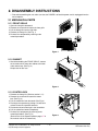
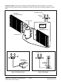
2.1.1 FRONT GRILLE
1. Open the inlet grille downward.
2. Remove the screw which fastens the front grille.
3. Pull the front grille from the right side.
4. Remove the front grille. (See Fig. 1)
5. Re-install the component by referring to the
removal procedure.
Cool
F1 LOW
F2 MED
F3 HIGH
Energy
Saver
'F
Fan
Timer
MODE
TIMER
TEMP
FAN
SPEED
POWER
Figure 1
2.1.2 CABINET
1. After disassembling the FRONT GRILLE, remove
the 6 screws which fasten the cabinet at the both
sides and the top. (See Fig. 2)
Keep these for later use.
Coo
Ener l
Savegy
r
Fan
F1
F2 LOW
F3 MED
HIGH
Tim
MO
DE
'F
er
TIM
ER
TEM
P
FAN
SPE
ED
POW
ER
Figure 2
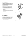
2.1.3 CONTROL BOX
1. Remove the front grille. (Refer to section 2.1.1)
2. Remove the screw which fasten the control
box. (See Fig. 3)
3. Pull the control box from the barrier.(See Fig.3)
4. Discharge the capacitor by placing a 20,000 ohm
resistor across the capacitor terminals.
5. Disconnect two wire housings in the control box.
6. Pull the control box forward completely.
7. Re-install the components by referring to the
removal procedure. (See Fig. 3)
(Refer to the circuit diagram found on pages 27 in
this manual and on the control box.)
Copyright ©2007 LG Electronics. Inc. All right reserved.
Only for training and service purposes
Co
ol
En
erg
Sav y
er
Fa
n
F1
F2 LOW
F3 MED
HIGH
Tim
MO
'F
er
DE
TE
TIM
MP
ER
FA
SP N
EE
D
PO
WE
R
Figure 3
-7-
LGE Internal Use Only
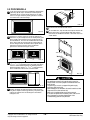
2.2 AIR HANDLING PARTS
2.2.1 ORIFICE, AND TURBO FAN
1. Remove the front grille. (Refer to section 2.1.1)
2. Remove the cabinet. (Refer to section 2.1.2)
3. Remove the 2 screws which fasten the
evaporator at the left side and the right side.
(See Fig. 4)
4. Move the evaporator sideward carefully.
Coo
Ener l
Savegy
r
Fan
F1
F2 LOW
F3 MED
HIGH
Time
r
MO
DE
'F
TEM
P
TIM
ER
FAN
SPE
ED
POW
ER
Figure 4
5. Remove the orifice. (See Fig. 5)
Coo
Ener l
Savegy
r
Fan
F1
F2 LOW
F3 MED
HIGH
Time
'F
r
MOD
TEM
E
TIM
P
ER
FAN
SPE
ED
POW
ER
Figure 5
8. Using handheld pliers, remove the clamp which
secures the turbo fan. (See Fig. 6)
Coo
Ener l
Savegy
r
Fan
F1
F2 LOW
F3 MED
HIGH
Time
'F
r
MOD
TEM
E
TIM
P
ER
FAN
SPE
ED
POW
ER
Figure 6
9. Remove the turbo fan with pliers or your hand,
without touching blades. (See Fig. 7)
10. Re-install the components by referring to the
removal procedures, above.
Coo
Ener l
Savegy
r
Fan
F1
F2 LOW
F3 MED
HIGH
Time
'F
r
MOD
TEM
E
TIM
P
ER
FAN
SPE
ED
POW
ER
Figure 7
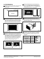
2.2.2 FAN
1. Remove the cabinet. (Refer to section 2.1.2)
2. Remove the brace.
(Refer to section 2.2.1)
3. Remove the 7 screws which fasten the condenser.
4. Move the condenser sideways carefully.
5. Using handheld pliers, remove the clamp which
secures the fan.
6. Remove the fan. (See Fig. 8)
7. Re-install the components by referring to the
removal procedures, above.
Copyright ©2007 LG Electronics. Inc. All right reserved.
Only for training and service purposes
Figure 8
-8-
LGE Internal Use Only
2.2.3 SHROUD
1. Remove the fan. (Refer to section 2.2.2)
2. Remove the shroud. (See Fig. 9)
3. Re-install the components by referring to the
removal procedures, above.
2.3 ELECTRICAL PARTS
2.3.1 MOTOR
1. Remove the cabinet. (Refer to section 2.1.2)
2. Remove the clamp cord and disconnect the wire
housing in control box. (Refer to section 2.1.3)
3. Remove the turbo fan. (Refer to section 2.2.2)
4. Remove the fan. (Refer to section 2.2.2)
5. Remove the 4 or 2 screws which fasten the motor.
(See Fig. 10)
6. Remove the motor.
7. Re-install the components by referring to the
removal procedures, above.
Figure 9
2.3.2 COMPRESSOR
1. Remove the cabinet. (Refer to section 2.1.2)
2. Discharge the refrigerant system using a FreonTM
Recovery System.
If there is no valve to attach the recovery system
to, install one (such as a WATCO A-1) before
venting the FreonTM . Leave the valve in place after
servicing the system.
3. Disconnect the 3 leads from the compressor.
4. After purging the unit completely, unbraze the
suction and discharge tubes at the compressor
connections.
5. Remove the 3 nuts and the 3 washers which
fasten the compressor. (See Fig. 11)
6. Remove the compressor.
7. Re-install the components by referring to the
removal procedures, above.
Figure 10
Figure 11
2.3.3 CAPACITOR
1. Remove the control box. (Refer to section 2.1.3)
2. Remove the 1 screw
3. Open the control box
4. Disconnect all the leads on the capacitor terminals.
5. Re-install the components by referring to the
removal procedures, above.
Co
ol
En
erg
Save y
r
Fa
n
Tim
MOD
F1
F2 LOW
F3 MED
HIG
H
TIM
'F
er
TE
MP
E
ER
FA
SP N
EE
D
PO
WER
Figure 12
Copyright ©2007 LG Electronics. Inc. All right reserved.
Only for training and service purposes
-9-
LGE Internal Use Only
2.3.4 POWER CORD
1. Remove the control box. (Refer to section 2.1.3)
2. Unfold the control box. (Refer to section 2.3.3)
3. Disconnect the grounding screw from the Base
pan.
4. Disconnect 2 receptacles.
5. Remove a screw which fastens the clip cord.
6. Pull the power cord. (See Fig. 13)
7. Re-install the components by referring to the
removal procedure, above.
(Use only one ground-marked hole, , for ground
connection.)
8. If the supply cord of this appliance is damaged, it
must be replaced with the factory-authorized and
specified cord.
Figure 13
Co
ol
En
er
Sav gy
er
Fa
n
2.3.5 THERMISTOR
Tim
MO
1. Remove the control box. (Refer to section 2.1.3)
2. Unfold the control box. (Refer to section 2.3.3)
3. Disconnect all the leads of thermistor terminals.
4. Remove the thermistor. (See Fig. 14)
5. Re-install the components by referring to the
removal procedures, above.
F1
F2 LOW
F3 MED
HIGH
'F
er
DE
TE
TIM
MP
ER
F
SP AN
EE
D
PO
WE
R
Figure 14
Copyright ©2007 LG Electronics. Inc. All right reserved.
Only for training and service purposes
- 10 -
LGE Internal Use Only
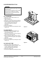
2.4 REFRIGERATION CYCLE
CAUTION
Discharge the refrigerant system using a FreonTM
Recovery System.
If there is no valve to attach the recovery system,
install one (such as a WATCO A-1) before
venting the FreonTM. Leave the valve in place
after servicing the system.
2.4.1 CONDENSER
1. Remove the cabinet. (Refer to section 2.1.2)
2. Remove the brace.
(Refer to section 2.2.1)
3. Remove the 7 screws which fasten the condenser.
4. After discharging the refrigerant completely into a
FreonTM Recovery System, unbraze the
interconnecting tube at the condenser
connections.
5. Remove the condenser.
6. Re-install the components by referring to the notes
(See Fig. 15)
Figure 15
2.4.2 EVAPORATOR
1. Remove the cabinet. (Refer to section 2.1.2)
2. Discharge the refrigerant completely – into a
FreonTM Recovery System.
3. Remove the 2 screws which fasten the evaporator
at the left side and the right side.
4. Move the evaporator sideward carefully and then
unbraze the interconnecting tube at the evaporator
connectors.
5. Remove the evaporator.
6. Re-install the components by referring to the notes
(See Fig. 16)
Coo
Ene l
Savrgy
er
Fan
F1
F2 LOW
F3 MED
HIGH
Tim
MO
'F
er
DE
TEM
TIM
P
ER
FAN
SPE
ED
PO
WE
R
Figure 16
2.4.3 CAPILLARY TUBE
1. Remove the cabinet. (Refer to section 2.1.2)
2. After discharging the refrigerant completely – into
a FreonTM Recovery System, unbraze the
interconnecting tube at the capillary tube.
3. Remove the capillary tube.
4. Re-install the components by referring to the notes.
Copyright ©2007 LG Electronics. Inc. All right reserved.
Only for training and service purposes
- 11 -
LGE Internal Use Only
NOTES
— Replacement of the refrigeration cycle.
1. When replacing the refrigeration cycle, be sure to
discharge the refrigerant system using a FreonTM
recovery System.
If there is no valve to attach the recovery system,
install one (such as a WATCO A-1) before venting
the FreonTM. Leave the valve in place after
servicing the system.
2. After discharging the unit completely, remove the
desired component, and unbrace the pinch-off
tubes.
3. Solder service valves into the pinch-off tube ports,
leaving the valves open.
4. Solder the pinch-off tubes with Service valves.
5. Evacuate as follows.
1) Connect the vacuum pump, as illustrated Fig.
17A.
2) Start the vacuum pump, slowly open manifold
valves A and B with two full turns
counterclockwise and leave the valves closed.
The vacuum pump is now pulling through valves
A and B up to valve C by means of the manifold
and entire system.
CAUTION
If high vacuum equipment is used, just crack
valves A and B for a few minutes, then open
slowly with the two full turns counterclockwise.
This will keep oil from foaming and being
drawn into the vacuum pump.
6. Recharge as follows :
1) Refrigeration cycle systems are charged from the
High-side. If the total charge cannot be put
in the High-side, the balance will be put in the
suction line through the access valve which you
installed as the system was opened.
2) Connect the charging cylinder as shown in Fig. 17B.
With valve C open, discharge the hose at the
manifold connection.
3) Open valve A and allow the proper charge to
enter the system. Valve B is still closed.
4) If more charge is required, the high-side will not
take it. Close valve A.
5) With the unit running, open valve B and add the
balance of the charge.
a. Do not add the liquid refrigerant to the Lowside.
b. Watch the Low-side gauge; allow pressure to
rise to 30 lbs.
c. Turn off valve B and allow pressure to drop.
d. Repeat steps B and C until the balance of the
charge is in the system.
6) When satisfied the unit is operating correctly,
use the pinch-off tool with the unit still running
and clamp on to the pinch-off tube. Using a tube
cutter, cut the pinch-off tube about 2 inches from
the pinch-off tool. Use sil-fos solder and solder
pinch-off tube closed. Turn off the unit, allow it to
set for a while, and then test the leakage of the
pinch-off connection.
3) Operate the vacuum pump for 20 to 30 minutes,
until 600 microns of vacuum is obtained. Close
valves A and B, and observe vacuum gauge for
a few minutes. A rise in pressure would
indicate a possible leak or moisture remaining in
the system. With valves A and B closed, stop
the vacuum pump.
4) Remove the hose from the vacuum pump and
place it on the charging cylinder. See Fig. 17B.
Open valve C.
Discharge the line at the manifold connection.
5) The system is now ready for final charging.
Copyright ©2007 LG Electronics. Inc. All right reserved.
Only for training and service purposes
- 12 -
LGE Internal Use Only
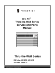
Equipment needed: Vacuum pump, Charging cylinder, Manifold gauge, Brazing equipment. Pinch-off tool
capable of making a vapor-proof seal, Leak detector, Tubing cutter, Hand Tools to remove components, Service
valve.
COMPOUND GAUGE
CONDENSER
(HIGH PRESSURE SIDE)
MANIFOLD
GAUGE
A
B
CAPILLARY TUBE
SEE INSETS
BELOW
EVAPORATOR
(LOW PRESSURE SIDE)
COMPRESSOR
LOW
HI
A
B
B
A
EXTERNAL
VACUUM PUMP
CHARGING
CYLINDER
C
Figure 17A-Pulling Vacuum
Copyright ©2007 LG Electronics. Inc. All right reserved.
Only for training and service purposes
Figure 17B-Charging
- 13 -
LGE Internal Use Only
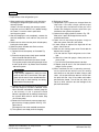
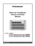
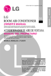
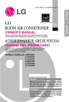
3. INSTALLATION
INSTALLATION HARDWARE
3.1 INSTALLATION REQUIREMENTS
If you use an existing wall sleeve, you should measure its
dimensions.
Install the new air conditioner according to these installation
instructions to achieve the best performance. All wall sleeves
used to mount the new air conditioner must be in good
structural condition and have a compatible rear grille in order
to securely attach the new air conditioner. (FIG. 18A)
With the FRIEDRICH USC sleeve, you can maintain the
best performance of the new air conditioner. (FIG. 18B)
2
1
4
5
2 Size options
6
8
9
10
3
7
20-3/32"
(511 mm)
2 Size options
24"(610 mm)
ITEM
➀
➁
➂
➃
➄
➅
➆
➇
➈
➉
14-13/32"
(366 mm)
18-15/32"(468 mm)
Air Conditioner
FIG. 18A
25-7/8"
(656 mm)
NAME OF PARTS
PLASTIC GRILLE
VERTICAL INSULATION STRIP
AROUND INSULATION STRIPS
HORIZONTAL INSULATION STRIP
SUPPORT BLOCK
BAFFLE
TRIM FRAME
SHIM
PLASTIC NUTS AND WASHER SCREWS
GRILLE REAR
Q'TY
1
1
2
1
2
1
2
2
4
1
CAUTION
To avoid risk of personal injury, property damage, or
product damage due to the weight of this device and sharp
edges that may be exposed:
• Air conditioners covered in this manual pose an
excessive weight hazard. Two or more people are
needed to move and install the unit.
To prevent injury or strain, use proper lifting and carrying
techniques when moving unit.
• Carefully inspect location where air conditioner will be
installed. Be sure it will support the weight of the unit
over an extended period of time.
• Handle air conditioner with care. Wear protective gloves
whenever lifting or carrying the unit. AVOID the sharp
metal fins of front and rear coils.
• Make sure air conditioner does not fall during installation.
15-17/32"
(394 mm)
aluminum metal grille
16-23/32"
(425 mm)
FRIEDRICH USC Wall Sleeve
FIG. 18B
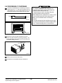
ELECTRICAL SERVICE
Check your available electrical service. The power supply
available must be the same as that shown on the unit
nameplate (found on left side of cabinet).
All models are equipped with a 3-prong service plug to
provide proper service and safe positive grounding. Do not
change plug in any way. Do not use an adapter plug. If your
present wall outlet does not match your plug, call a qualified
electrician to make the necessary corrections. SAVE
CARTON for storage and this OWNER'S MANUAL for future
reference. The carton is the best way to store unit during
winter or when not in use.
Copyright ©2007 LG Electronics. Inc. All right reserved.
Only for training and service purposes
REQUIRED TOOLS:
• Tight Fitting gloves
• Standard screwdriver
• Phillips screwdriver
• Pliers
• Sharp knife
- 14 -
• 3/8-inch open end
wrench or adjustable
wrench
• 1/4-inch hex socket
and ratchet
• Tape measure
• Electric drill
• 1/4-inch drill bit
LGE Internal Use Only
3.2 INSTALLATION
NOTE: All wall sleeves used to mount the new Air
Conditioner must be in sound structural condition and have a
rear grille that securely attaches to sleeve, or rear flange that
serves as a stop for the Air Conditioner.
CAUTION
Installing the FRIEDRICH USC sleeve ensures
optional performances of the unit.
If you decide to keep the existing wall sleeve, you have
to redirect the louvers at the back of the wall sleeve.
Refer to FIG. 23 on p15. The use of pliers is
recommended. If you DO NOT redirect, you run the risk
of poor performance or premature product failure. This
is not covered under the terms of the FRIEDRICH
warranty.
2
3
• Pick a location which will allow the conditioned air to blow
into the area you want. Good installation with special
attention to the proper position of the unit will lessen the
chance that service will be needed.
Remove old air conditioner from existing wall sleeve.
Clean the interior of an existing sleeve.
(Do not disturb seals.)
4
Wall sleeve must be securely fastened in wall before
installing the air conditioner. Use the nails or screws
through sleeve into wall, if needed. Repaint sleeve if
needed.
5
Prepare the wall sleeve for installation of the unit. If you
plan to use your existing wall sleeve, and it is not
FRIEDRICH, use procedure B or C below.
Procedure
A(page 16)
ITEMS IN INSTALLATION HARDWARE
You may not need all parts in the kit. Discard unused parts
ITEM (inches)
Plastic grille
263/4 x 161/2
Vertical insulation strip
159/16 x 13/8 x 13/8
1/8 x 13/8 x 25/32
67
Around Insulation Strips
5927/32 x 13/8 x 13/8
Horizontal Insulation Strip
237/32 x 13/8 x 13/16
Support Block
13/4 x 13/8 x 45/16
Baffle
14 x 41/2 x 1/8
Shim
1113/16 x 1 x 3/4
Trim Frame
Washer Screw
Nuts(Plastic)
Grille Rear
Qty.
1
1
1
1
1
2
1
2
2
4
4
1
B
(pages 17~18)
C
(pages 19)
6
HOW TO INSTALL
installing the unit, identify the existing wall sleeve
1 Before
from the list below.
Brand
White-Westinghouse
Frigidaire
Carrier (52F series)
General Electric
/Hotpoint
Whirlpool
Fedders/Emerson
Friedrich WSC
FRIEDRICH USC
Emerson/Fedders
Carrier (51S Series)
15-1/4
16, 17-1/2
or 22
26
15-5/8
16-7/8
25-7/8
16-1/2
27
16-3/4
25-7/8
26-3/4
25-3/4
15-17/32
15-3/4
16-7/8
Copyright ©2007 LG Electronics. Inc. All right reserved.
Only for training and service purposes
Depth(inches)
16-23/32
16, 17-1/2
or 22
16-7/8
17-1/8 or 23
18-5/8
16-3/4
or 19-3/4
15
Install new unit into wall sleeve.
CAUTION: When installation is completed, replacement unit
MUST have a rearward slope as shown. To achieve 1/4"
slope, remove the backing from the 11-13/16" shim strips and
attach them as shown below in Fig. 19. Place the higher
portion of shim to the front of the rib on base of wall sleeve.
Wall Sleeve Dimensions (inches)
Width
Height
Depth
25-1/2
Brand
FRIEDRICH USC
White-Westinghouse
Frigidaire Carrier
(52F series)
General Electric
/Hotpoint
Whirlpool
Carrier (51S series)
Fedders/Emerson
Friedrich WSC
Emerson/Fedders
1" high
3/4" High
UNIT
FRONT
Shim
17-1/8
or 23
16-3/4
or 19-3/4
16-23/32
15
18-5/8
6"
6"
SHIM PLACEMENT
Wall Sleeve
1/4"
UNIT INSTALLATION
FIG. 19
- 15 -
LGE Internal Use Only
3.3 PROCEDURE A
1
Plastic rear grille
Steel rear grille
If you are using the new sleeve (optionally supplied with
your unit),skip to step 3. Otherwise, install the plastic
grille from the kit. Cut the plastic grille to 25-1/2" wide
and 15-1/4" high. Place the plastic grille to the inside of
the wall sleeve at the rear flange.
FIG. 23
FIG. 20
2
5
Install the new unit into the wall sleeve.
6
To assemble trim, snap the tab of each piece into the slot
of the other piece as shown below. Slide trim over the
front of the air conditioner until trim is flush with sleeve as
shown below.
Fasten the 4 washer screws to secure the grille to the
wall sleeve. If you need plastic nuts to mount plastic grille
to the inside of the wall sleeve, there are plastic nuts in
the installation kit. The nuts are installed from the inside
of the sleeve and are pressing into the square holes of
the rear flanges.Fasten the bracket to the upside of the
wall sleeve using the washer screw. The bracket
prevents the unit from leaving the sleeve.
Trim (2 ea)
Bracket
Bracket
Wall
Fasten the screws and the bracket
3
or
FIG. 21
Remove the backing from the Vertical Insulation strip
159/16 x 13/8 x 13/8 and attach that to the inside right of the
sleeve as shown below. Remove the backing from the
Around Insulation strip 671/8 x 13/8 x 25/32 and attach that
to the inside front of the sleeve as shown below.
Indoor
Outdoor
FIG. 24
Around Insulation
CAUTION
Vertical Insulation
9 1/2"
4
6"
FIG. 22
Remove the metal rear grille and replace it with the plastic
rear grille to improve unit energy efficiency. The plastic grille
reduces the amount of hot air discharge that recirculates
through the unit.
Copyright ©2007 LG Electronics. Inc. All right reserved.
Only for training and service purposes
• Air conditioners covered in this manual pose an excessive
weight hazard. Two or more people are needed to move and
install the unit.
To prevent injury or strain, use proper lifting and carrying
techniques when moving unit.
• When handling the air conditioner, be careful to avoid cuts from
sharp metal fins on front and rear coils.
• Make sure air conditioner does not fall during removal.
• If unit does not operate after installation check, to be sure the
circuit interrupter has not been tripped. Refer to the
Troubleshooting guide for reset procedure.
- 16 -
LGE Internal Use Only
3.4 PROCEDURE B
1
4
Redirect the louvers at the back of the wall sleeve to 60°
angle as shown in the FIG 25. The use of pliers is
recommended.
Remove the backing from the Vertical Insulation strip
159/16 x 13/8 x 13/8 and attach that to the inside right of the
sleeve as shown below. Remove the backing from the
Around Insulation strip 671/8 x 13/8 x 25/32 and attach that to
the inside front of the sleeve as shown below.
Indoor
7 3/32"
Outdoor
60°
60°
Rear Louvers
Around Insulation
Vertical Insulation
(Top View)
9 1/2"
6"
FIG. 28
FIG. 25
2
5
If the wall sleeve already has a rear grille, skip to step 4.
If the wall sleeve does not have a rear grille or louvered
panel, install the plastic grille from the kit. Cut the plastic
grille to 25-1/2" wide and 15-1/4" high. Place the plastic
grille to the inside of the wall sleeve at the rear flange.
Remove the metal rear grille and replace it with the
plastic rear grille to improve unit energy efficiency. The
plastic grille reduces the amount of hot air discharge that
recirculates through the unit.
Plastic rear grille
Steel rear grille
FIG. 29
Place the plastic grille
3
FIG. 26
Fasten the 4 washer screws to secure the grille to the
wall sleeve. If you need plastic nuts to mount plastic grille
to the inside of the wall sleeve, there are plastic nuts in
the installation kit. The nuts are installed from the inside
of the sleeve and are pressed into the square holes of
the rear flanges.Fasten the bracket to the upside of the
wall sleeve using the washer screw. The bracket
prevents the unit from leaving the sleeve.
6
If the depth of your existing wall sleeve is less than or
equal to 18", skip to step 7. Otherwise, cut the baffles
and the support blocks according to length "A" in the
table below.
Depth"D" of the existing Length "A"
wall sleeve (inches)
(inches)
18
18-5/8
5
D 18- /8
D 19-3/4
19-3/4 D
Bracket
22
A
Support
Block
3 4
/
1-3/4
4
Baffle
A
FIG. 30
Bracket
or
Fasten the screws and the bracket
Copyright ©2007 LG Electronics. Inc. All right reserved.
Only for training and service purposes
FIG. 27
- 17 -
LGE Internal Use Only
PROCEDURE B CONTINUED
7
Remove the backing from the support blocks and attach
them to the inside of the wall sleeve as shown FIG 31.
Slide the baffle into slots of the support blocks.
(7 3/32")
Wall
Wall
Sleeve
Baffle
Front
Support
Block
FIG. 31
8
Install the new unit into the wall sleeve.
9
Assemble trim as described in Step 6,
Procedure A.
CAUTION
• Air conditioners covered in this manual pose an
excessive weight hazard. Two or more people are
needed to move and install the unit.
To prevent injury or strain, use proper lifting and carrying
techniques when moving unit.
• When handling the air conditioner, be careful to avoid
cuts from sharp metal fins on front and rear coils.
• Make sure air conditioner does not fall during removal.
• If unit does not operate after installation check, to be sure
the circuit interrupter has not been tripped. Refer to the
Troubleshooting guide for reset procedure.
Copyright ©2007 LG Electronics. Inc. All right reserved.
Only for training and service purposes
- 18 -
LGE Internal Use Only
3.5 PROCEDURE C
1
4
Redirect the louvers at the back of the wall sleeve to 60°
angle as shown in the FIG 32. The use of pliers is
recommended.
Remove the backing from the Horizontal Insulation strip
237/32 x 13/8 x 13/16 and attach that to the inside right of the
sleeve as shown below. Remove the backing from the
Around Insulation strip 5927/32 x 13/8 x 13/8 and attach that
to the inside front of the sleeve as shown below.
7 13/16"
Indoor
Outdoor
60°
60°
Rear Louvers
Around Insulation
Horizontal Insulation
(Top View)
8 1/2"
FIG. 32
2
FIG. 35
If the wall sleeve already has a rear grille, skip to step 4. If the
wall sleeve does not have a rear grille or louvered panel, install
the plastic grille from the kit. Cut the plastic grille to 26-1/2"
wide and 15-1/2" high or to the sleeve dimensions. Place the
plastic grille to the inside of the wall sleeve at the rear flange.
5
If the depth of your existing sleeve is less than or equal
to 18”, skip to step 7. Otherwise, cut the baffles and the
support blocks according to Length "A" in the table
below.
Depth"D" of the existing Length "A"
wall sleeve (inches)
(inches)
5
18
3
6
FIG. 33
Place the plastic grille
Fasten the 4 washer screws to secure the grille to the
wall sleeve. If you need plastic nuts to mount plastic grille
to the inside of the wall sleeve, there are plastic nuts in
the installation kit. The nuts are installed from the inside
of the sleeve and are pressed into the square holes of
the rear flanges. Fasten the bracket to the upside of the
wall sleeve using the washer screw. The bracket
prevents the unit from leaving the sleeve.
/
1-3/4
D 19-3/4
19-3/4 D
4
22
Bracket
Copyright ©2007 LG Electronics. Inc. All right reserved.
Only for training and service purposes
A
FIG. 36
(7 3/32")
Wall
Baffle
Wall
Sleeve
Support
Block
FIG. 37
or
Fasten the screws and the bracket
Baffle
Remove the backing from the support blocks and attach
them to the inside of the wall sleeve as shown FIG 37.
Slide the baffle into slots of the support blocks
Front
Bracket
Support
Block
3 4
D 18- /8
18-5/8
A
FIG. 34
- 19 -
LGE Internal Use Only
3.5 PROCEDURE C CONTINUED
7
CAUTION
To achieve rearward slope for unit draining, remove the
backing from the 1113/16" shim strips and attach them as
shown below in Fig. 39. The higher portion of shim is to
be placed in front of the rib on the base of wall sleeve.
1" high
3/ "
4
High
FIG. 38
• Air conditioners covered in this manual pose an
excessive weight hazard. Two or more people are
needed to move and install the unit.
To prevent injury or strain, use proper lifting and
carrying techniques when moving unit.
• When handling the air conditioner, be careful to avoid
cuts from sharp metal fins on front and rear coils.
• Make sure air conditioner does not fall during
removal.
• If unit does not operate after installation check, to be
sure the circuit interrupter has not been tripped. Refer
to the Troubleshooting guide for reset procedure.
Shim (2EA)
6"
6"
FIG. 39
8
Remove the metal rear grille and replace it with the
plastic rear grille to improve unit energy efficiency. The
plastic grille reduces the amount of hot air discharge that
recirculates through the unit.
Plastic rear grille
Steel rear grille
FIG. 40
9
Install the new unit into the wall sleeve
10
Assemble trim as described in Step 6, Procedure A.
Copyright ©2007 LG Electronics. Inc. All right reserved.
Only for training and service purposes
- 20 -
LGE Internal Use Only
4. TROUBLESHOOTING GUIDE
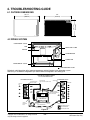
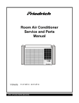
4.1 OUTSIDE DIMENSIONS
20-3/32"
(499mm)
24"
(610mm)
Cool
'F
F1 LOW
F2 MED
F3 HIGH
Energy
Saver
Fan
TEMP
Timer
TIMER
FAN
SPEED
POWER
14-13/32"
(366mm)
MODE
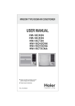
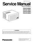
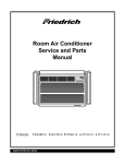
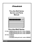
4.2 PIPING SYSTEM
CONDENSER COILS
FAN
CAPILLARY TUBE
MOTOR
COMPRESSOR
TURBO FAN
EVAPORATOR COILS
: REFRIGERANT FLOW
Following is a brief description of the important components and their functions in the refrigeration system.
Refer to Fig. 41 to follow the refrigeration cycle and the flow of the refrigerant in the cooling cycle.
ROOM AIR CONDITIONER
CYCLE OF REFRIGERATION
EVAPORATOR COILS
CONDENSER COILS
COMPLETE LIQUID
BOIL OFF POINT
COOLED
AIR
SUCTION LIME
COOL LOW PRESSURE VAPOR
VAPOR INLET
HOT
DISCHARGED
AIR
ROOM AIR HEAT LOAD
MOTOR
OUTSIDE COOLING
AIR FOR REFRIGERANT
PASS THROUGH
COMPRESSOR
OIL
LIQUID
PRESSURE
DROP
LIQUID OUTLET
(LIQUID REFRIGERANT)
Figure 41
Copyright ©2007 LG Electronics. Inc. All right reserved.
Only for training and service purposes
HIGH PRESSURE VAPOR
LIQUID PEFRIGERANT
CAPILLARY TUBE
- 21 -
LOW PRESSURE VAPOR
LGE Internal Use Only
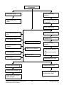
4.3 TROUBLESHOOTING GUIDE
In general, possible trouble is classified in two causes.
The one is called Starting Failure which is caused from an electrical defect, and the other is Ineffective Air
Conditioning caused by a defect in the refrigeration circuit and improper application.
Unit is running but cooling is ineffective
Ineffective Cooling
Check cold air circulation
for smooth flow.
Check outdoor coil
(heat exchanger) & the fan
operation.
Dirty indoor coil
(Heat exchanger)
Check gas leakage.
Malfunction of fan
Repair gas leak.
Clogged air filter
Replacement of unit if the
unit is beyond repair.
Check heat load increase.
Unexpected residue
Overloaded Circuit
Check inside gas pressure.
Obstruction at air outlet
Adjusting of refrigerant
charge
Stop auto air-swing
Malfunction of compressor
Correct above troubles
Replacement of
compressor
Check clogging in
refrigeration circuit.
Repair clogging in
refrigeration circuit.
Satisfactory operation with
temperature difference of
inlet & outlet air ; 44.6~50˚F
Copyright ©2007 LG Electronics. Inc. All right reserved.
Only for training and service purposes
- 22 -
LGE Internal Use Only
Fails to Start
Check power source.
Check circuit breaker
and fuse.
Check control switch
setting.
Gas leakage at feeler bulb
of thermostat
Check control switch.
Only compressor fails to
start.
Only fan fails to start.
Improper wiring.
Drop in power voltage.
Improper thermostat setting
Defect of fan motor
capacitor.
Defective compressor
capacitor.
Loose terminal connection.
Check capacitor.
Irregular motor resistance
( ).
Irregular motor insulation
( ).
Improper wiring
Replacement.
Replacement of fan motor
Irregular motor resistance ( )
Regular but fails to start
Irregular motor insulation ( )
Replacement of compressor
(locking of rotor, metal)
Replacement of compressor
(Motor damaged)
Copyright ©2007 LG Electronics. Inc. All right reserved.
Only for training and service purposes
- 23 -
LGE Internal Use Only
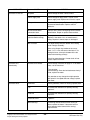
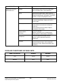
COMPLAINT
Fan motor will not run.
CAUSE
REMEDY
No power
Check voltage at outlet. Correct if none.
Power supply cord
Check voltage to rotary switch. If none, check
power supply cord. Replace cord if circuit is open.
Rotary switch
Check switch continuity. Refer to wiring diagram
for terminal identification. Replace switch if
defective.
Wire disconnected or
connection loose
Connect wire. Refer to wiring diagram for terminal
identification. Repair or replace loose terminal.
Capacitor (Discharge
capacitor before testing.)
Test capacitor.
Replace if not within ±10% of manufacturer's
rating. Replace if shorted, open, or damaged.
Will not rotate
Fan blade hitting shroud or blower wheel hitting
scroll. Realign assembly.
Units using slinger ring condenser fans must
have 1/4 to 5/16 inch clearance to the base. If it is
hitting the base, shim up the bottom of the fan
motor with mounting screw(s).
Check fan motor bearings; if motor shaft will not
rotate, replace the motor.
Fan motor runs
intermittently
Revolves on overload.
Check voltage. See limits on page 27. If not within
limits, call an electrician.
Test capacitor.
Check bearings. Does the fan blade rotate freely?
If not, replace fan motor.
Pay attention to any change from high speed to
low speed. If the speed does not change, replace
the motor.
Fan motor noise.
Grommets
Check grommets; if worn or missing, replace them.
Fan
If cracked, out of balance, or partially missing,
replace it.
Turbo fan
If cracked, out of balance, or partially missing,
replace it.
Loose set screw
Tighten it.
Worn bearings
If knocking sounds continue when running or
loose, replace the motor. If the motor hums or
noise appears to be internal while running,
replace motor.
Copyright ©2007 LG Electronics. Inc. All right reserved.
Only for training and service purposes
—24—
- 24 -
LGE Internal Use Only
COMPLAINT
Compressor will not run,
but fan motor runs.
CAUSE
REMEDY
Voltage
Check voltage. See the limits on the preceding.
page. If not within limits, call an electrician.
Wiring
Check the wire connections, if loose, repair or
replace the terminal. If wires are off, refer to wiring
diagram for identification, and replace. Check wire
locations. If not per wiring diagram, correct.
Rotary
Check for continuity, refer to the wiring diagram
for terminal identification. Replace the switch if
circuit is open.
Thermostat
Check the position of knob If not at the coldest
setting, advance the knob to this setting and
restart unit.
Check continuity of the thermostat. Replace
thermostat if circuit is open.
Capacitor (Discharge
capacitor before
servicing.)
Check the capacitor.
Replace if not within ±10% of manufacturers
rating. Replace if shorted, open, or damaged.
Compressor
Check the compressor for open circuit or
ground. If open or grounded, replace the
compressor.
Check the compressor overload, if externally
mounted. Replace if open. (If the compressor
temperature is high, remove the overload, cool it,
and retest.)
Overload
ROOM AIR CONDITIONER VOLTAGE LIMITS
NAME PLATE RATING
MINIMUM
MAXIMUM
115V
103.5V
126.5V
208/230V
187V
253V
Copyright ©2007 LG Electronics. Inc. All right reserved.
Only for training and service purposes
- 25 -
LGE Internal Use Only
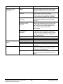
COMPLAINT
Compressor cycles
on overload.
Insufficient cooling or
heating
Excessive noise.
REMEDY
CAUSE
Voltage
Check the voltage. See the limits on the preceding page. If not within limits, call an electrician.
Overload
Check overload, if externally mounted.
Replace if open. (If the compressor temperature
is high, remove the overload, cool, and retest.)
Fan motor
If not running, determine the cause. Replace if
required.
Condenser air flow
restriction
Remove the cabinet. inspect the interior surface
of the condenser; if restricted, clean carefully
with a vacuum cleaner (do not damage fins) or
brush. Clean the interior base before
reassembling.
Condenser fins
(damaged)
If condenser fins are closed over a large area
on the coil surface, head pressures will increase,
causing the compressor to cycle. Straighten the
fins or replace the coil.
Test capacitor.
Check the terminals. If loose, repair or replace.
Check the system for a restriction.
If restricted, clean of replace.
Close if open.
Determine if the unit is properly sized for the area to
be cooled.
Check the set screw or clamp. If loose or missing,
correct. If the blower or fan is hitting air guide,
rearrange the air handling parts.
Remove the cabinet and carefully rearrange tubing
not to contact cabinet, compressor, shroud, and
barrier.
Capacitor
Wiring
Refrigerating system
Air filter
Exhaust damper door
Unit undersized
Blower or fan
Copper tubing
Copyright ©2007 LG Electronics. Inc. All right reserved.
Only for training and service purposes
- 26 -
LGE Internal Use Only
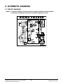
5. SCHEMATIC DIAGRAM
5.1 CIRCUIT DIAGRAM
• MODEL : LT1230CR/LT1030CR/LT1010CR/LT1430CR/LT1210CR/LT100CSG/LT120CSG/LT0810CR
LT1010CRY6/LT1030CRY6/LT1210CRY6/LT1430CRY6/LT080CSG/LT121CSG
Copyright ©2007 LG Electronics. Inc. All right reserved.
Only for training and service purposes
- 27 -
LGE Internal Use Only
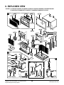
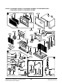
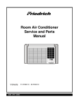
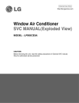
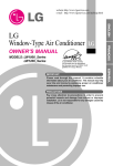
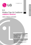
6. EXPLODED VIEW
• MODEL: LT1230CR/LT1030CR/LT1010CR/LT1430CR/LT1210CR/LT100CSG/LT120CSG/LT0810CR
LT1010CRY6/LT1030CRY6/LT1210CRY6/LT1430CRY6/LT080CSG/LT121CSG
E
152302
147581
132100
147582A
135303
147582B
131400
149980
135312
W48602
559011
359012
354210
435300A
346811
435300
435301
349480
352380
554031
349600
731273
147900
130410
A
264110
W6631
268711A
249951
B
567480
C
352115
268711B
35211A
Co
ol
En
erg
Save y
r
Fa
n
F1
F2 LOW
F3 MED
HIG
H
Tim
DE
TIM
ER
554160
W0CZZ
'F
er
MO
TE
MP
FA
SP N
EE
D
PO
WER
238310
237200
352113
267110
Copyright ©2007 LG Electronics. Inc. All right reserved.
Only for training and service purposes
- 28 -
552113
550140
LGE Internal Use Only
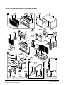
• MODEL: LXC103BLMK1.AWYBULI / LXC103BLMK1.AWYBHDP / LXC103BLMK0.AWYBULI
LXC081BLMK1.AWYBULI / LXC081BLMK1.AWYBCIL
E
152302
147581
132100
147582A
135303
147582B
131400
149980
135312
W48602
559011
359012
354210
435300A
346811
435300
435301
349480
352380
554031
731273
147900
130410
A
264110
W6631
268711A
249951
B
567480
C
352115
268711B
35211A
Co
ol
En
erg
Save y
r
Fa
n
F1
F2 LOW
F3 MED
HIG
H
Tim
DE
TIM
ER
554160
W0CZZ
'F
er
MO
TE
MP
FA
SP N
EE
D
PO
WER
238310
237200
352113
267110
Copyright ©2007 LG Electronics. Inc. All right reserved.
Only for training and service purposes
- 29 -
552113
550140
LGE Internal Use Only
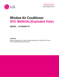
• MODEL: LXC143BLMK2.AWYBULI / LXC143BLMK1.AWYBUSL
E
152302
147581
132100
147582A
135303
147582B
131400
149980
135312
W48602
559011
359012
354210
435300A
346811
435300
435301
349480
352380
554031
349600
731273
130410
A
264110
W6631
268711A
249951
B
567480
C
352115
268711B
35211A
Co
ol
En
erg
Save y
r
Fa
n
F1
F2 LOW
F3 MED
HIG
H
Tim
DE
TIM
ER
554160
W0CZZ
'F
er
MO
TE
MP
FA
SP N
EE
D
PO
WER
238310
237200
352113
267110
Copyright ©2007 LG Electronics. Inc. All right reserved.
Only for training and service purposes
- 30 -
552113
550140
LGE Internal Use Only
P/NO : 3828A20294P
January, 2008