1
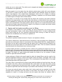
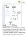
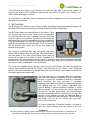
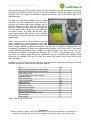
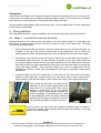
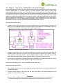
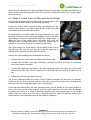
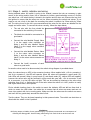
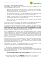
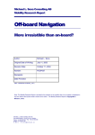
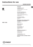
BioTuning Twin-Tank Kit Guide v2.3 BioTuning Twin-Tank Kit (Version 2) Fitting and Operation Guidelines. The BioTuning Twin-Tank Kit is a comprehensive set of parts that can be used to run a diesel vehicle on natural, unmodified vegetable oil. Once installed, the vehicle becomes a diesel/vegoil hybrid, able to run on vegetable oil, mineral diesel or blends of the two. Twin-tank hybrid systems have proven to be the most reliable method of running diesel vehicles on vegetable oil. The BioTuning Twin-Tank Kit brings together some of the very best, most highly regarded components in a single and complete twin-tank conversion package. From heated filter, heat exchanger and fuel select valves to wiring looms, hoses, fittings and clips. Everything likely to be needed is provided, except for the second fuel tank (which is not provided since each vehicle owner will have different requirements and preferences). These fitting guidelines describe a ‘typical’ installation in detail, enabling a competent home mechanic to relatively quickly convert a vehicle to run on vegetable oil. The guidelines are intended to be instructional and educational; helping the vehicle user to fully understand the conversion, how the components operate and how to get the best out of their vegetable oil motoring. The fuel selection in this kit is achieved via a pair of solenoid 3 port valves which are controlled independently, enabling the vehicle to be run on diesel or on vegetable oil and allowing for a complete purge of vegetable oil to the diesel tank at the end of each journey, ensuring that the vehicle is started on pure diesel when cold. This enables good clean starts even in the coldest weather conditions. The BioTuning kit is suitable for vehicles fitted with; inline pump-line injector systems eg, Mercedes Benz prechamber engines (W123 W124 etc) axle piston pumps eg Bosch VE, Bosch VP37, Zexel, Nippon Denso, Diesel-kiki The BioTuning kit may be suitable (with additional components and precautions) for vehicles fitted with; unit injectors eg pumpe duse common rail systems rotary pumps eg Lucas CAV, Bosch VP44, Bosch VA As with all diesel /vegetable oil hybrid kits, it is the responsibility of the vehicle owner to ensure that the kit is suitably matched to both the vehicle and their operating expectations. Although the kit comprises high quality and reliable components, it is fitted to vehicles at the owners risk. BioTuning accepts no liability for the failure of any vehicle component or for any consequential losses that may occur. 1 Vehicle operation A vehicle fitted with a BioTuning Twin Tank Kit can be run on vegetable oil as follows; The vehicle has two fuel tanks, one tank, typically the main tank, holds the vegetable oil and the other tank, perhaps a small second tank contains diesel fuel. The vehicle is started and run on diesel fuel while the engine is warming up. Once the engine has warmed up to operating temperature, the switch can be pressed to the vegoil position, powering both of the solenoid valves and changing the fuel used from diesel to vegetable oil. For the rest of the journey, the Disclaimer BioTuning accept no liability for any personal injury or problems encountered as a consequence of following this fitting guide. Persons fitting a BioTuning Twin Tank Kit do so at their own risk. 1 BioTuning Twin-Tank Kit Guide v2.3 vehicle can run on neat vegoil. The vehicle can be stopped and started as required provided it is not allowed to cool significantly. When the engine is hot, the water from the vehicle's coolant system (which will now be between 70 and 90°C) is used to heat the vegoil. A highly efficient heat exchanger warms the vegoil to within a few degrees of the coolant water temperature. When the oil is heated, its viscosity decreases (it becomes runnier) and when heated sufficiently, vegetable oil can be burned cleanly in a diesel engine as though it were mineral diesel. If the vehicle is to be left for long enough that the engine will cool down, the switch should be pressed to the purge position near or at the end of the journey, to flush the fuel lines and injector pump of vegetable oil, priming them with diesel. After 30 seconds or so in the purge position, the switch can be placed back in the diesel position and the engine run for another 60 seconds which will prime the injector pump and fuel lines, ready for the vehicle to be easily and cleanly started from cold on diesel fuel for the next journey. 2 Engine and fuel system condition prior to fitting. If the engine or fuel system are in poor condition, are poorly configured or not running correctly (eg, poor performance, smoky, erratic idling, difficulty starting) then it is best to address these issues before fitting the kit. Any problems experienced when running on diesel are likely to become more troublesome when running on vegetable oil. 3 System overview The system is typically installed as shown in Figure 1 and operates as follows; The vehicle is fitted with a small second tank to hold diesel. A new fuel supply line is fitted to this tank and run to the engine where it is connected to the existing diesel filter This supplies diesel to the engine for the warm up period and during the purge cycle. A second fuel line is fitted to the tank and run to the engine where it is connected to the return valve. This is to send the unburned diesel fuel back to the second tank when running on diesel. A coolant heated fuel filter is installed and this is fitted to the existing fuel supply line from the main fuel tank. The heat makes the filtering process more efficient and puts less strain on the injector pump and fuel lines. The vehicle now has two fuel filters, one for diesel and a heated one for vegoil. This allows for faster purging and enables the vehicle to be run normally on diesel should the vegoil filter become blocked. A heat exchanger is fitted to the vegoil supply line after the heated filter to get the vegoil to the optimum temperature before it is fed into the injector pump and engine. The supply valve is used to select which fuel is supplied to the engine. This is connected to the diesel filter, to the vegoil heat exchanger and to the injector pump. The return valve is connected to the injector pump and the existing and new fuel return lines are connected to the return valve so that unburned fuel is sent back to the main tank when running on vegoil or purging and to the diesel tank when on diesel. Lastly, the vehicles coolant is diverted through the vegoil filter and heat exchanger to provide the heat necessary to thin the vegoil. The three port solenoid valves select which fuel is being used and are operated via the dash mounted switch. Depending upon the position of the switch, the valves can be used to run on vegetable oil, diesel or to purge and prime the fuel system with diesel. An indicator LED is Disclaimer BioTuning accept no liability for any personal injury or problems encountered as a consequence of following this fitting guide. Persons fitting a BioTuning Twin Tank Kit do so at their own risk. 2 BioTuning Twin-Tank Kit Guide v2.3 provided to give easy identification of the switch position; this is unlit when running on diesel, green when using vegetable oil and red when purging. Figure 1. Schematic diagram of the BioTuning Twin-Tank Kit (v2) While the vehicle is warming up, it is run on diesel with the switch in the O position and the unused fuel is returned back to the diesel tank. When the vehicle reaches normal operating temperature, the coolant flowing through the heated filter and the heat exchanger provides enough heat to thin vegoil such that it can be used in place of diesel fuel. At this point the switch can be pressed to the II position, and the engine run on neat vegetable oil. It should be noted that the vehicle will run perfectly well on diesel if left in the O position. In both the diesel and vegoil switch positions, the unused fuel is returned to the selected fuel tank. The purge is activated by changing the switch to the I position. This draws the fuel supply from the diesel tank, and returns the unused fuel to the vegoil tank, thus quickly flushing the vegoil out Disclaimer BioTuning accept no liability for any personal injury or problems encountered as a consequence of following this fitting guide. Persons fitting a BioTuning Twin Tank Kit do so at their own risk. 3 BioTuning Twin-Tank Kit Guide v2.3 of the fuel lines and injector pump ready for the next cold start. After a brief period (around 30 seconds) the vehicle can be switched to diesel mode (O position) to prime it for a minute or so, ready to be started again on diesel. It is possible to use the main tank for diesel and to hold the vegetable oil in the second fuel tank should this be preferred. 4 Kit Contents The BioTuning kit is made up of the highest quality automotive specification parts throughout. At the heart of the kit are the fuel valves, the heat exchanger and the heated filter; The BioTuning valves are solenoid driven 3 port valves. There is a common fuel port on each valve which is connected to one fuel port when the valve is powered and the other port when the valve is not powered. The valves are designed and built specifically for use in vegetable oil twin tank conversions. They are constructed from brass and stainless steel with viton seals and are suitable for fluids between -20°C and +130°C. The kit contains two valves; one for the fuel supply and another for the return. The system is configured with both the supply and return valves used for diesel when not powered. This ensures that if the fuse blows or any other wiring failure occurs then the vehicle will continue to run safely on diesel. Vegetable oil is selected with both valves powered and the purge is with the supply valve not powered (selecting diesel) and the return valve powered (selecting the vegoil tank), flushing the vegoil with diesel and ensuring no vegoil contamination of the diesel tank. The wiring loom supplied with the kit has a four-core wire for the valves. The wires are labelled to indicate which should be used for the “Supply” valve and which for the “Return” valve. Wiring the valves in the way indicated by the labelled wires will ensure that the valves operate correctly for the vegoil, diesel and purge modes. The heat exchanger is a compact plate heat exchanger which has been designed especially for fuel / water heat transfer in vehicles for vegetable oil heating. Constructed from aluminium, the heat exchanger is extremely lightweight and reaches temperature exceptionally quickly with minimal heat loss. It is precision engineered with internal baffles to induce turbulence resulting in highly efficient transfer of heat between the coolant water and the fuel. For the best performance, the heat exchanger should be connected with the fuel flowing in the opposite direction to the coolant to provide the maximum heat to the fuel as it leaves the heat exchanger. The hose fittings are 12mm (1/2”) ID for the coolant hose and 8mm (5/16”) ID for fuel hose. It is worth noting that if mounted vertically, it is best to have the vegoil entering from the lowest of the fuel Disclaimer BioTuning accept no liability for any personal injury or problems encountered as a consequence of following this fitting guide. Persons fitting a BioTuning Twin Tank Kit do so at their own risk. 4 BioTuning Twin-Tank Kit Guide v2.3 fittings and leaving from the highest, with the coolant flowing in the opposite direction since this minimises the likelihood of fuel air locks in the heat exchanger. Revving the engine will provide sufficient flow in the coolant to release any trapped air that may occur in the coolant side of the heat exchanger. The filter is an extremely efficient coolant heated fuel filter. The fuel is heated as it enters and exits the filter by a brazed plate heat exchanger that is installed between the filter head and the spin-on filter. As a result this filter unit gets exceptionally hot very quickly and provides very good efficiency for filtering vegoil. The large spin-on filter gives good range between filter changes and is certified for biodiesel so will not break down when used with heated vegoil. Table 1 shows a parts list for the BioTuning Kit. All other components in the BioTuning kit are high quality, reliable automotive specification parts with class ‘A’ vegoil materials compliance throughout. The fuel hose is to SAEJ30 R6 specifications and is suitable for vegetable oil, diesel and unleaded petrol between -20°C and +120°C. The coolant hose to SAEJ20R3 specification and is suitable for coolant between -40°C and +120°C. The hose connectors are suitable for temperatures between -20°C + 110°C, and pressures up to 200psi. The wires, are military grade automotive specification and are pre-fitted with insulated crimp connectors. An indicator LED and an in-line fuse holder with splash proof cover make up the electrical fittings. In addition, the kit contains all the hose clips, hose connectors, electrical connectors (pre-fitted) cable ties and rubber grommets that should be required. Item BioTuning 8mm vegetable oil solenoid valve Double pole double throw on-off-on switch Dash indicator LED Compact Brazed Plate Heat Exchanger Heated Fuel Filter 16mm Coolant hose 12mm Coolant Hose 8mm fuel hose 10mm fuel hose 8mm nylon fuel line Bag of hose connectors Bag of fuel hose clips Bag of coolant hose clips Wiring looms with connectors fitted Bag of sundries Fitting Guide Qty 2 1 1 1 1 2m 3m 5m 1m 10m 2 2 2 1 1 1 Table 1. BioTuning Kit Parts List. Disclaimer BioTuning accept no liability for any personal injury or problems encountered as a consequence of following this fitting guide. Persons fitting a BioTuning Twin Tank Kit do so at their own risk. 5 BioTuning Twin-Tank Kit Guide v2.3 5 Fitting overview You should allow 5 to 10 hours to complete the fitting. As with all vehicle maintenance, it is advisable to allow plenty of time to avoid rushing. The conversion can be undertaken in a number of stages and the vehicle can be operated between the stages, allowing the flexibility to progress the conversion in the time you have available. Make sure you allow plenty of time to plan the work. This cannot be stressed enough. It is essential that before you begin any work, you have assembled all of the parts you need and planned exactly where they will be best located within the space available. Consider where the fuel and coolant hose and the electrical wiring can be routed. Taking time to get this right can make the difference between completing a good, tidy conversion and making a mistake! Be sure to read the rest of the fitting guidelines completely so that it is clear how the kit is installed and where the new parts are fitted in relation to the existing vehicle components. Try offering the heated filter, the heat exchanger and the valves to the various spaces around the engine to test for fit. Observe the orientation of the ports and try to arrange the components so that the hoses are not folded, likely to rub against moving or hot parts or putting stress on the hose connectors. Considering the following at the planning stage should be very helpful when undertaking the actual conversion; Locate the injector pump, and its supply and the return hoses. Locate the fuel hoses running from and to the main fuel tank. Locate the heater hoses passing through the bulkhead to the internal heater matrix. Try to keep the fuel valves and heat exchanger as close to injector pump as possible. This minimises fuel heat loss along the fuel lines between the heat exchanger and the injector pump and it minimises the purge time resulting in less diesel being required to perform the purge. Try to locate the heated filter in an accessible location where there is plenty of space available for changing the filter element. Make sure all fuel hose, coolant hose or wires can’t come into contact with moving or hot parts (eg auxiliary belts, alternator, fans, exhaust manifold, wiper motor, vibrating engine components etc) If space is limited, can the existing fuel filter be moved to another location to free up some space? Is there enough capacity in the fuel line trunking or retaining clips for the new fuel line from the second tank. Are there any rubber grommets already available for passing the fuel line and wires through the vehicle bulkhead or chassis. Where can the second tank be best located. Once you have planned where all the parts are going to go and how they will be connected together, it is time to check that you have all the tools that you require. Here is a short-list of some tools you may need; Screwdrivers Molegrips Sockets and ratchet driver Spanners Pliers Power drill Voltmeter Hose clamp, cutter or sharp knife Disclaimer BioTuning accept no liability for any personal injury or problems encountered as a consequence of following this fitting guide. Persons fitting a BioTuning Twin Tank Kit do so at their own risk. 6 BioTuning Twin-Tank Kit Guide v2.3 Fitting hints. Some of the hose fittings and connectors can be very tight. By immersing the hose in hot water for a short while, the rubber can be softened making it easier to push on. Be careful using hot water and make sure to thoroughly flick off any water before fitting fuel lines. Be conservative (overestimate) when measuring hoses. You can always trim off a few centimetres to tidy things up afterwards. 6 Fitting guidelines The steps below describe a typical installation with the second tank being used for diesel fuel. 6.1 Stage 1 – second tank and new fuel lines. Although listed first, this stage can be undertaken at any time before Stage 5. In this stage, the second tank is fixed in place and fuel lines are run from the tank to the engine bay. The steps involved are described below; Fit the second fuel tank and mount it securely. Using the 8mm nylon fuel line provided, run a length of fuel line from near the second tank to the engine bay near or before the existing diesel fuel filter. Mark the ends of the hose to identify this line as the fuel supply. Connect the nylon fuel line to the fuel supply outlet on the second tank using a length of the supplied rubber fuel hose. To make a secure connection on the nylon hose, insert one of the brass support sleeves into the nylon before pushing over the rubber 8mm fuel hose. Seal using a hose clip, taking care that the hose clip is over the brass insert to prevent the nylon from being crushed. If the fuel tank outlet is for hose of a larger bore use the supplied fuel reducers, 10mm hose and additional hose clips as required to make secure connections. A second length of nylon line should be run from near the new fuel tank to the same location in the engine bay. Connect this to the fuel return inlet on tank, again using a support sleeve, hose clip and length of 8mm rubber fuel hose to make good connections. When fitting the fuel lines, use cable ties as necessary to secure them, keeping them well away from hot or moving parts such as the exhaust or suspension. Try to use existing trunking, clips or undercarriage channels as much as possible. If grommets can be used to pass bulkheads, then use these, otherwise carefully drill through any bulkheads and use the provided grommets to protect the hoses. Seal the end of the fuel hoses with a piece of electrical tape or similar to prevent dirt ingress whilst passing them through the trunking or through gaps in the undercarriage. Disclaimer BioTuning accept no liability for any personal injury or problems encountered as a consequence of following this fitting guide. Persons fitting a BioTuning Twin Tank Kit do so at their own risk. 7 BioTuning Twin-Tank Kit Guide v2.3 6.2 Stage 2 – fuel valves, heated filter and heat exchanger. Having planned good locations for the solenoid valves and heat exchanger near the injector pump and the heated filter in a location where it is easily serviced, secure them in place using appropriate hardware (eg bolts, nuts, self-tapping screws). The valves can be rotated inside the coil housing and also the connector block can be fitted with different orientations. Be aware that vibrations may work the components loose if they are not attached using thread lock, spring washers or nylock nuts. Decide which valve will be used for fuel supply and which for fuel return. Avoid mounting the heat exchanger in a location where it will be exposed to engine vibrations or the hoses leading to it will be under tension or vibrating. These conditions can, over time, lead to fatigue failure of the hose tails caused by repeated bending back and forth. First connect the diesel lines; Locate the fuel supply hose that runs from the diesel filter to the injector pump. Divert this so that it runs from the diesel filter to fuel port number 3 (see Figure 2) of the supply valve, and from fuel port number 1 of the supply valve to the injector pump. Figure 2. Valve fuel ports and wiring Locate the fuel return hose on the injector pump that runs back to the fuel tank (it may go via the filter head). Divert this so that it runs from the injector pump to port number 1 of the return valve and from port number 3 to the original vehicle fuel tank. If this hose went via the diesel filter head, this should now be bypassed since it will prevent proper purging. If the return hose went via the diesel filter, the hose fittings on the fuel filter head will now be free. These should be connected together using a loop of fuel hose. At this point the vehicle can be driven on diesel from the main tank. Next connect the vegoil lines; Run a length of fuel hose from the top fitting on the heated filter to one of the fuel fittings on the heat exchanger. Connect another length of fuel hose from the other fuel fitting on the heat exchanger to port number 2 of the fuel select valve. Disclaimer BioTuning accept no liability for any personal injury or problems encountered as a consequence of following this fitting guide. Persons fitting a BioTuning Twin Tank Kit do so at their own risk. 8 BioTuning Twin-Tank Kit Guide v2.3 Check all hose connections for leaks and tighten down the hose clips if required. Use cable ties to secure all fuel hose ensuring that it does not come into contact with sharp, hot or moving parts, and does not rub. 6.3 Stage 3 -heater hoses to filter and heat exchanger In this stage the coolant lines are tee’d and new hoses used to run coolant to the heated fuel filter and the heat exchanger. Locate the coolant hoses running through the bulkhead to the internal heater matrix. It is best to add a new coolant loop that runs parallel to the internal heater matrix. Do not progress to this step unless the engine coolant is cold – feel the hoses to make sure you will not get scalded. If you do not have hose clamps to seal the coolant lines, drain the coolant water to below the level of the heater hoses just before they enter the bulkhead (use a suitable container to catch the coolant that is drained. It can be used to top up the expansion tank later). Use a hose cutter or a sharp knife to cut the heater hoses close to the bulkhead. Slip over the hose clips and insert the equal tee or reducing tee as required to make tight connections. Connect the heat exchanger and heated filter as follows; Connect from one of the tees to the filter using 16mm hose. Connect from the filter to the heat exchanger, reducing from 16mm to 12mm en-route using one of the reducers provided. Connect the remaining hose fitting on the heat exchanger back to the other tee in the heater matrix lines via the other 16 to 12 reducer to increase the hose bore back up to 16mm for the tee. Tighten up all connections with hose clips. Top up the coolant and start the vehicle. Check for leaks and tighten the hose clips if necessary. Check the coolant level once more and use cable ties to secure all coolant hose ensuring that it does not come into contact with sharp, hot or moving parts. Check that the heated filter and heat exchanger both get hot quickly as the vehicle begins to warm. If they do not, there may be an air lock in the new coolant loop. This can often be released by parking the vehicle on a slope so that the expansion tank is the highest point in the coolant system. Start the vehicle and rev it up, to vigorously push the coolant around the heater lines. Check that the new components heat up and repeat if necessary. Disclaimer BioTuning accept no liability for any personal injury or problems encountered as a consequence of following this fitting guide. Persons fitting a BioTuning Twin Tank Kit do so at their own risk. 9 BioTuning Twin-Tank Kit Guide v2.3 6.4 Stage 4 - switch, indicator and wiring Having decided where the switch is going to be located, remove the trim as necessary to gain access to the wiring and/or fuses. Use a voltmeter to locate a good switching source of 12volts; one which has +12v when the key is turned in the ignition and 0v when not. Remove the key from the ignition to ensure that the wires are not live when connecting the switch and valves. If you need to cut out a hole in the dash for mounting the switch it needs to be 22mm wide by 30mm tall. The wiring loom for the kit is pre-connected and the wires for the valves are labelled for the supply and return valve. To connect the wires correctly, follow the steps below; The red wire with the fuse should be connected to the switching 12v source. The black wire should be connected to a good earth. Connect the wire labelled 'Supply Valve 1' to the supply valve connector on fitting 1 and the wire labelled 'Supply Valve 2' to the supply valve connector on fitting 2. Connect the wire labelled 'Return Valve 1' to the return valve connector on fitting 1 and the wire labelled 'Return Valve 2' to the return valve connector on fitting 2. Connect the 'earth' connector of each valve to a good earth. In case the wires need to be disconnected, the switch wiring diagram is provided above. Note: the valves have an LED in the connector housing. When applied with +12v to connector 1 and 0v to connector 2, the LED will operate. When the valves are operated in vegoil mode (II), both LEDs will operate. When in purge mode (I) and diesel mode (O), neither LEDs will operate, however the return valve will be powered in purge mode but now with +12v to connector 2 and 0v to connector 1 so the LED does not light. This can be verified by listening to the valve when switching from 0 to I or feeling the coil of the valve when the switch is in the I position to verify that it gets warm after a short period. Find a suitable location close to the switch to mount the indicator LED and drill an 8mm hole in which to mount the LED holder. Use cable ties to ensure that all wires are secure and can not come into contact with hot or moving parts. Make sure that the wires near the switch are secure and can’t fall free, particularly around the driver’s feet. Test the valves. They can be heard operating in their powered state. The vehicle can be driven on diesel with the switch in the O position. Disclaimer BioTuning accept no liability for any personal injury or problems encountered as a consequence of following this fitting guide. Persons fitting a BioTuning Twin Tank Kit do so at their own risk. 10 BioTuning Twin-Tank Kit Guide v2.3 6.5 Stage 5 - final system configuration The final stage of the installation is to set up the fuel lines for running on vegetable oil from the main tank and diesel from the second tank. Starting with the fuel hose running from the main tank to the vehicle's original diesel filter, disconnect this hose from the filter and connect it to one of the hose tails on the side of the heated fuel filter. Use new fuel hose if necessary. The return hose to the main tank is currently connected to the return solenoid valve at fuel port number 3. This needs to be removed and connected to fuel port number 2. In Stage 1, the supply fuel line from the second fuel tank was labelled. This should now be connected to the vehicles original fuel filter inlet hose tail. Lastly, the return fuel line for the second tank should be connected to the return solenoid valve fuel port number 3. The fuel lines are now connected correctly for running the twin tank system with vegetable oil in the main tank and diesel in the second tank. The second tank can be filled with diesel. The new fuel lines will be empty of fuel; it is necessary to prime them. This can be achieved by disconnecting the hose from the injector pump inlet and using a priming bulb or other pump attached to this hose to draw the diesel through the new fuel lines. Be prepared with a container to catch the fuel that is drawn out of the hose and dispose of it appropriately (it may contain debris). Initially diesel from the filter will be pumped through followed by some air from the new fuel supply line and then diesel once more when the fuel supply line is full. Next, the heated filter and heat exchanger need to be primed. To reduce the amount of fuel that needs to be pumped through, the filter should be removed, topped up with diesel and spun back onto the housing. The switch should be set to the II position and the key should be turned in the ignition so that the indicator LED is green. Again pump on the primer to draw through the fuel until there is no more air drawn through the pump. Once finished, reconnect the hose to the input hose tail on the injector pump. Please note: if you do not have a hand priming pump, the engine's injector pump can be used to prime the fuel lines by running the engine in diesel mode (O) and if it stalls, turning the engine over until it fires again. Next switch to veg model (II) and repeat. Topping up the filter with diesel beforehand can greatly help if priming this way. Congratulations, your twin-tank kit installation is now complete. See the next section for a few general points on operating the vehicle and keeping the system in good order. 7 Running tips, vehicle maintenance and trouble shooting When running on vegetable oil, especially if running on filtered used vegetable oil, it is good to be aware of a few aspects to keep your vehicle running smoothly. Some of these aspects and recommendations are listed below; • The water temperature gauge in the dashboard can give a good indication of when the vehicle is warm and it is safe to switch over to vegetable oil. Disclaimer BioTuning accept no liability for any personal injury or problems encountered as a consequence of following this fitting guide. Persons fitting a BioTuning Twin Tank Kit do so at their own risk. 11 BioTuning Twin-Tank Kit Guide v2.3 • • • • • • • • • • • The time taken for the fuel to purge fully is approximately 30 seconds followed by approximately 60 seconds in diesel mode. If the vehicle is found to be grumpy when starting from cold, it may be worth noting that a slightly longer purge should help, or allowing it to run in diesel mode for longer after purging. During cold weather, it may be necessary to put a small amount of diesel into the vegetable oil tank (say 10 – 20%) to lower the fuel viscosity and make it easier for the injector pump to draw the fuel along the lines from the tank. If you are unable to fill up with vegetable oil on a long journey, it is fine to fill the vegetable oil tank with diesel. For the first fill up, the residual vegoil will give good lubrication to the pump compensating for the warming of the diesel. After this, it would be good practice to add say 5% of vegoil to ensure good pump lubrication. It is important that the vegoil filter is drained regularly to remove any water that may have accumulated in the bottom of the filter. If water were to reach the injectors, serious damage would occur. The vegoil filter should be replaced more frequently than specified in the service manual, particularly if using waste vegoil. The filter is more likely to clog when running on filtered used cooking oil. This will be revealed as fuel starvation and the vehicle lacking power. It is wise to carry a spare fuel filter at all times. The oil level should be checked more frequently than indicated in the service manual and changed more regularly (say every 6000 to 10,000 miles). If the level of oil is seen to rise it is important to undertake an oil and oil filter change as soon as possible since this indicates polymerisation of the engine oil. Check coolant and fuel lines regularly to make sure that nothing is rubbing or leaking. Check coolant level regularly. Top up if needed and check for leaks if observed to drop. If the vehicle starves for fuel, particularly when demanding power from the engine, it is a good sign of air entering the fuel lines. If the vehicle was running well before the problem started, it is likely that there is a vacuum being caused in the fuel line. In which case, the filter may need changing or if the weather is cold, a nip of diesel in the vegoil tank may solve matters. If the problem is more prevalent, it is likely that there is a poor seal in a fuel line and it is best to check all hose connectors, banjo bolts and hose clips. It is also worth checking the filter element or head for an air leak. Some vehicles may require an additional electric pump in the fuel line to push the thicker vegetable oil to the injector pump. This can be switched to run only when vegoil is selected by connecting the pump +12v lead to the left middle pin of the switch when viewing the back of the switch with I up and the 0v lead to a good earth. The kit is transferable and can easily be removed and added to another vehicle, returning your donor vehicle to its original operation. Footnote We hope you have many years of green, economical and trouble free vegoil motoring using this kit. Please contact us if you experience any trouble with the kit or would like to suggest possible improvements that could be made. If you wish to contact BioTuning, please do so via the contact details on our website. These can be found at www.BioTuning.co.uk, alternatively, email [email protected] for a prompt response. Thank you for choosing a BioTuning Twin-Tank Kit. Disclaimer BioTuning accept no liability for any personal injury or problems encountered as a consequence of following this fitting guide. Persons fitting a BioTuning Twin Tank Kit do so at their own risk. 12