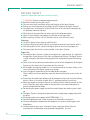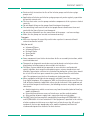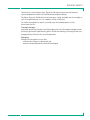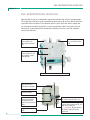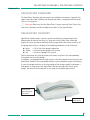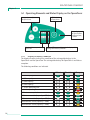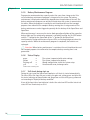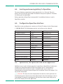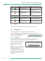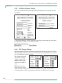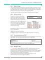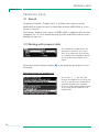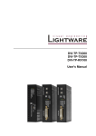
1
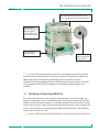
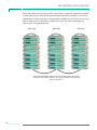
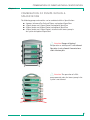
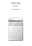
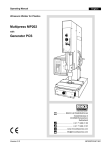
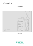
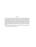
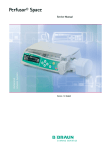
SpaceStation
and SpaceCom
Instructions for Use
GB Valid for Software 695F
CONTENTS
Patient Safety ..............................................................................................................................4
Chapter 1
The SpaceStation in Detail................................................................................8
1.1 Fastening a Single SpaceStation .................................................................................................9
1.2 Assembly and Disassembly of Pillars ........................................................................................10
1.3 Combining Individual SpaceStations .......................................................................................10
Chapter 2
Chapter 3
Chapter 4
Chapter 5
Combination of Pumps within a SpaceStation ..........................................13
Inserting and Removing Individual Pumps .................................................14
SpaceCover Standard ......................................................................................15
SpaceCover Comfort........................................................................................15
5.1 Operating Elements and Status Display on the SpaceCover ...............................................16
5.1.1 Display of Battery Condition .......................................................................................... 16
5.1.2 Switching On/Off .............................................................................................................17
5.1.3 Volume Control .................................................................................................................17
5.1.4 Brightness Sensor .............................................................................................................17
5.1.5 Battery Maintenance Program ......................................................................................18
5.1.6 Status Display ...................................................................................................................18
5.1.7 Self check during start up ................................................................................................18
Chapter 6
Interfaces for Data Communication.............................................................19
6.1
6.2
6.3
6.4
6.5
6.6
Intended Use.................................................................................................................................19
The connectors of SpaceCom ....................................................................................................20
Status Displays ............................................................................................................................20
Inserting and removing battery for SpaceCom .......................................................................21
Configuration SpaceCom Interfaces.........................................................................................21
SpaceOnline, the SpaceCom Web Server Application............................................................21
6.6.1 Setting of a network connection....................................................................................22
6.6.2 Login....................................................................................................................................22
6.7 Status.............................................................................................................................................23
6.8 Service............................................................................................................................................24
6.9 Configuration................................................................................................................................24
6.9.1 User Settings......................................................................................................................24
6.9.1.1 Change Password .................................................................................................25
6.9.1.2 Change Username................................................................................................25
6.9.1.3 Change access authorization.............................................................................25
6.9.2 WLAN and Ethernet Settings ..........................................................................................26
6.9.3 BCC Protocol Settings ......................................................................................................26
6.9.4 Battery Settings.................................................................................................................27
6.9.5 Database Settings .............................................................................................................27
6.9.6 Time synchronization via SNTP.......................................................................................27
6.10 Wireless LAN.................................................................................................................................27
Chapter 7
Proposal data....................................................................................................28
7.1 General
.............................................................................................................................30
7.2 Working with proposal data.......................................................................................................30
Chapter 8
Chapter 9
Chapter 10
Datalogger
................................................................................................31
Service
................................................................................................32
Guarantee..........................................................................................................33
10.1 Maintenance ................................................................................................................................33
10.2 Hygienics / Disposal ....................................................................................................................33
10.3 Rechargeable Batteries ..............................................................................................................34
Chapter 11
Technical Data..................................................................................................35
11.1
11.2
11.3
11.4
Ordering
B. Braun SpaceStation without B. Braun SpaceCom ............................................................35
B. Braun SpaceStation with B. Braun SpaceCom ..................................................................36
B. Braun SpaceCover comfort ...................................................................................................37
B. Braun SpaceCover standard ..................................................................................................38
.............................................................................................................39
3
PATIENT SAFETY
PATIENT SAFETY
Important Information and Notes for Patient Safety
w Attention: Consult accompanying documents!
a
a
a
a
Read Instructions for Use prior to use.
The user must check functional safety and integrity of the Space System.
Prior to use check functions of the Space System: Valid only for Space System.*
Functional tests and Technical Safety Checks have to be carried out separately for
all additional connected devices.
a Check and set up connections to mains and further plug connections.
a Check if mains voltage corresponds to indication on the type plate!
a When connected, check staff call (simulate alarm, staff call must react).
Warnings:
a Use of the Space System only by qualified staff.
a Use Space System only when you are instructed to work with and familiar with it.
a This Instructions for Use is part of the Space Systems necessary for proper use.
a The Instructions for Use have to be available at the Space System.
Proper Use:
a The modular Space System is made for treatment of a single patient. It is especially
designed for use on Intensive Care Units and Operating Theatres. The Space System
is used in hospital. Operation mainly by physicians and medically qualified nursing
staff.
a Check if the current software and hardware version of the components of the Space
System are the same as this Instructions for Use refers to.
a At fm mobil, accessory for mobile use, it is not permitted to use short stands, as the
centre of gravity of the Space System may change.
a Insert receptacle suspension of the fm mobil before transport.
Check stability and secure position, especially when fastening the system to the fm
mobil.
a Prevent the fm mobil from rolling away on horizontal surfaces by using the locking
device. If there is an incline of more than 5°, additional locking is necessary.
a When the pumps in the Space System are switched off the control systems are not
active. Therefore, close roller clamp or selector valve at the connection point to
prevent uncontrolled backflow.
a Do not plug the power supply lead into the socket before the whole system is built
up.
a The Space System is designed for operation with a single power supply connection
per pillar.
a All configurations must comply with IEC/EN 60601-1-1.
a Possible explosion hazard if used in presence of flammable anesthetics!
a Use only compatible combinations of equipment, accessories, working parts and
disposables.
a Use only original spare parts. Functional safety is only guaranteed if by the
manufacturer recommended resp. compatible disposables are used.
4
PATIENT SAFETY
a Read carefully Instructions for Use of the infusion pumps and infusion syringe
pumps used.
a Application of infusion and infusion syringe pumps only under regularly supervision
by specially trained staff.
a The user must make sure the pumps and other components of the system are locked
correctly.
a Do not deposit things on the pumps. Avoid leaning on the pumps!
a The connecting leads must be laid so that people do not stumble over them and
work with the Space System is not hampered.
a Do not place disposable near the connections of the pumps – use hose routings.
a Make sure the pumps are inserted and removed correctly.
Transport:
a With max. 4 pumps. Be especially careful when a patient is connected. Avoid
external mechanical action!
Only for use of:
a Infusomat® Space
a Infusomat® Space P
a Perfusor® Space
a SpaceControl
a SpaceCom
a Some components have further Instructions for Use or assembly instructions, which
need to be observed.
a Therapeutic or diagnostic conclusions must not be based exclusively on values
displayed on infusion pumps or data available via interfaces.
a The Space System should only be operated in areas which are well protected
against vibration, dust corrosive and explosive gases, extreme temperatures and
humidity. To guarantee sufficient air circulation for cooling the system, there should
be at least 5 cm of clear space around the system. Do not cover the ventilation
slots. The equipment must be free of condensate during operation.
a When equipment with high electro-magnetic radiation is used at the same time
(e.g. digital telephones, X-ray apparatus, MRI, etc.) interference may occur. This may
lead to display trouble or implausible values may be indicated. If these problems are
due to electro-magnetic interferences, the following measures may help to avoid or
solve them:
a Avoid using devices which are not necessary from the medical point of view (e.g.
mobile telephones).
a Extend distance between source of interference and the medical product.
a Alter position of power supply leads, connection leads and electrodes.
a The EMC-limits (electro-magnetic compatibility) according to IEC/EN 60601-1-2
and IEC/EN 60601-2-24 are maintained. If the equipment is operated in the vicinity
of other equipment which may cause high levels of interference (e.g. HF surgical
equipment, nuclear spin tomography units, mobile telephones) maintain the
recommended protective distances for these devices.
5
PATIENT SAFETY
a The Space System should not be exposed to excessive magnetic fields (e.g. in an
MRI room). If necessary, longer infusion lines can be used. When using a
defibrillator, precautions must be observed which can be found in the
documentation for the defibrillator.
a For the safe use of Space infusion pumps in MRI the SpaceStation MRI is
recommended.
a In any case of central alarm (e.g. from staff call) it is necessary to check which
infusion pump caused the alarm. Only the specified alarm caused by the infusion
pump is relevant for safety.
Direct contact of the connectors of the SpaceStation during operation can lead
to malfunction due to electrostatic discharge.
Parallel infusion:
Compared to single infusions increased bolus volumes and alarm delay times may
occur!
Therefore:
If possible, select low pressure settings.
Pay attention to bigger bolus volumes and alarm delay times.
When removing sealing, do not let the bolus reach the patient.
A bolus reduction may lead to an underdosage of the drug when starting the
infusion again.
Recommendation: bolus reduction by opening the outward conducting system.
The bolus reduction may lead to dosage variations.
Higher personal supervision with critical drugs.
Immediate reaction in case of alarm!
When switching off a pump temporarily bolus administration is possible due to
enrichment of concentration at reduced flow.
International safety standards:
The Space System complies with:
a IEC/EN 60601-1,
a IEC/EN 60601-1-1,
a IEC/EN 60601-1-2 as well as
a IEC/EN 60601-2-24
and is CE marked in compliance with EU-Directive 93/42.
B. Braun Melsungen AG is certified according to DIN EN ISO 9001 and
DIN EN ISO 13485.
This certification also includes maintenance and service.
The visible LED’s comply to class 1 LED products according to IEC/EN 60825-1.
The B. Braun Space System is a flexible docking and communication system for the
medical workplace, in particular the intensive medical care, which substantially
contributes to the safety of its patients.
It serves the perspicuous accommodation of the infusion and infusion-syringe pumps
Infusomat® Space, Infusomat® Space P and Perfusor® Space, whose concrete
application is the medical professional decides on based upon guaranteed
6
PATIENT SAFETY
characteristics and technical data. The pillar and mounting system synchronized
system components enables the individualized workplace design.
The Space System is flexible due to fast and space saving assembly and disassembly as
well as the possibility to use it as a mobile, wall or ceiling unit.
Fur further descriptions as well as assembly resp. disassembly please see this
Instructions for Use.
Transport damages:
Inspection on delivery. Despite careful packaging, the risk of transport damage cannot
be entirely prevented. Upon delivery, please check that nothing is missing. Do not use a
damaged device. Contact the service department.
Packaging:
Packages are designed in a way that:
electrostatic charges are prevented and
batteries on printed boards cannot be discharged.
7
THE SPACESTATION IN DETAIL
Chapter 1
THE SPACESTATION IN DETAIL
SpaceStation serves to accommodate up to four infusion and infusion syringe pumps.
The single SpaceStations can be assembled to form one or up to three pillars which are
separated from each other. The individual pillars require their own mains supply and
are interconnected with each other via special extension cables. Every pillar must be
closed with a cover, SpaceCover Standard or Comfort, to ensure safe and complete
system functionality.
Mains voltage outlet to
the next SpaceStation;
F1B
Connector for further
SpaceStations or
SpaceCover comfort;
F5
Connector for Space
pump. Data lines and
12 V voltage supply;
F2A to F2D
Guide rails for the individual pumps
Central loudspeaker,
only contained in
SpaceCover comfort
Lever to release
universal clamp
Fixture of universal
clamp SP, rotatable
for attachment to
wall rails and infusion
poles
Mains power input;
F1A
8
Connection for extension cable
for further SpaceStation; F4
Connection for staff call, PCA
button, Connection Lead SP 12V
and service cable; F3
w Attention: Do not connect
the Power Supply SP to this
connector
THE SPACESTATION IN DETAIL
Chapter 1
Cover SpaceCover; must always cover the
uppermost segment. Serves at the same
time as carrying handle for a SpaceStation.
Rotary knob to
unlock single pumps.
Locking happens
automatically when
the pump is pushed
in.
Hose routings for
infusion tubing
Lock/unlock of
upper SpaceStation
or SpaceCover
w Attention: Every SpaceStation or one pillar consisting of several SpaceStations
must be covered with SpaceCover standard or comfort. The SpaceCover protects the
upper connections from humidity and damage and ensures perfect system
functionality. The SpaceStation and the individual pump are connected to each other
via the connectors F2A to F2D. The plugs are to be protected from damage and
humidity.
1.1 Fastening a Single SpaceStation
Every single SpaceStation can be attached to infusion poles and vertical tubes, e.g.
pendants suspension, as well as to horizontal wall rail systems according to EN 1789
without need of any further adapters or assembly auxiliaries. The rear universal clamp
can be rotated and has a quick-action mechanism. By pulling the release ring back, the
slide can be moved freely and prepositioned. Now the SpaceStation can be definitely
fixed by means of the set screw.
w Attention: Make sure that the SpaceStation is fastened correctly and safely after
9
THE SPACESTATION IN DETAIL
Chapter 1
By pulling the release ring back, the slide can be moved
freely for prepositioning.
assembly. Do not use tools to tighten the screw !
To release, first loosen the clamp by turning the adjusting knob half and then pull the
release ring in order to loosen the pole clamp using the quick gripping mechanism.
1.2 Assembly and Disassembly of Pillars
The upper segment is pushed on the lower segment from the front and fixed with the
locking in the lower segment.
To release, move the locking button in the corresponding position and take out the
upper segment to the front.
w Attention: Every single SpaceStation must be fixed to a fastening tube by means
of a fixation clamp.
1.3 Combining Individual SpaceStations
To mount one or multiple pillars the single SpaceStations can be assembled easily and
without any difficulties without requiring any special assembly tools.
The admissible combinations are listed in the following table:
10
THE SPACESTATION IN DETAIL
Chapter 1
1Pillar
2 Pillars
3 Pillars
A
A
B
A
B
C
SpaceCover Comfort
1
1
(1)
1
(1)
(1)
SpaceCover Standard
(1)
(1)
1
(1)
1
1
SpaceStation
1…6
1…5
1…5
1…4
1…4
1…4
Restriction
A≤6
(x) alternative usage possible
∑A+B≤6
∑A+B+C≤6
A,B,C number of SpaceStation in one pillar
w Attention: Other configurations, such as more than three pillars or exceeding the
number of SpaceStations within a pillar, are not permitted and result in
configuration error.
If a system consists of several pillars, these should be arranged logically and
physically from left to right.
Pillar 1(A)
Pillar 2(B)
Extension lead SP 60 or 120 cm. The lead is connected to F4
in pillar 1 and then to F3 in pillar 2.
w Attention: If the pillars will not be connected as described above, interchanging F4 and F3, there is a wrong topological representation in SpaceOnline and
wrong addressing in the BCC protocol.
11
THE SPACESTATION IN DETAIL
Chapter 1
Every single pillar must be covered with a SpaceCover standard or SpaceCover comfort.
If with a two or three pillars build up and only one SpaceCover comfort is used in this
combination all alarms and status information are displayed at this Cover. In case every
pillar is covered with a SpaceCover comfort the status and alarm information are
shown at the corresponding cover.
Pillar 1(A)
Pillar 2(B)
Pillar 3(C)
Extension lead SP 60 or 120 cm. The lead is connected to F4 in pillar
1 and then to F3 in pillar 2. Pillar 2 and 3 are interconnected with each
other via F3 and F4.
12
COMBINATION OF PUMPS WITHIN A SPACESTATION
Chapter 2
COMBINATION OF PUMPS WITHIN A
SPACESTATION
The following pumps and modules can be combined within a SpaceStation.:
• 4 pumps; Infusomat® or Perfusor® Space and optional SpaceCom
• 3 Space pumps and 1 SpaceControl and optional SpaceCom
• 2 Space pumps and 2 SpaceControl and optional SpaceCom
• 4 Space pumps and 1 SpaceControl, attached to the lowest pump in
the system and optional SpaceCom.
w Attention: Danger of tipping !
An operation as tabletop unit is not allowed.
Operation is only allowed if mounted on a
stable infusion pole.
w Attention: The operation of a fifth
pump mounted under the lowest pump in the
system is not allowed.
13
INSERTING AND REMOVING INDIVIDUAL PUMPS
Chapter 3
INSERTING AND REMOVING INDIVIDUAL PUMPS
w Attention: Before inserting a pump please ensure the vertical position of the side
rotary knob.
The guide rails of the SpaceStation must engage in the guide grooves of the pump.
The pump is then pushed with light pressure into the Space Station. The pump is
automatically locked in the system. The locking is to be recognized by the horizontal
position of the side rotary knob.
To release, turn the knob clockwise in the vertical position and remove the pump. After
release the pump is held in the SpaceStation by the guide rails, but can drop easily due
to strong vibrations or during transport.
w Attention: If a SpaceStation is used to transport infusion pumps make sure that
the pumps are correctly seated in the system.
A combination of Space pump and SpaceControl is installed in the SpaceStation in the
same way. In this case pump and SpaceControl are automatically and individually lokked. Before removal, first release the pump and then SpaceControl and then remove
both systems. For detailed information please refer the instructions for use of
SpaceControl.
w Attention: After connecting a pump the blue LED starts flashing for a short time.
In case the blue LED is illuminated constantly, a non critical fault is detected. By disconnecting and connecting the pump again, the fault could disappear, observe blue
LED. If the blue LED stays illuminated please inform the technical service. The pump
can be used furthermore but the status is not shown at the SpaceCover comfort,
green/yellow/red LED at cover, and communication with external systems, PDMS,
SpaceOneView, or staff call, is not working anymore. Status information are only
shown at the pump directly.
14
SPACECOVER STANDARD / SPACECOVER COMFORT
Chapter 4/5
SPACECOVER STANDARD
The SpaceCover Standard does not contain any additional electronics. It protects the
upper connectors from humidity and damage and allows a single SpaceStation to be
used as a carrying unit.
w Attention: Make sure that the SpaceCover is always correctly fixed. Please refer
also to the „Assembly and Disassembly Instructions” of the SpaceStation.
SPACECOVER COMFORT
SpaceCover Comfort offers a greater system functionality and operating facility.
Mounted on the front of the cover is a large and clearly visible status and alarm
display. All status and alarm conditions of the pumps within the system as well as of
the pumps themselves are displayed. The following conditions can be indicated:
• green -> OK; at least one pump in operation
• yellow -> prealarm of one pump in the system
• red
-> alarm of a pump in the system
Details concerning the single prealarms and alarms are given in the corresponding
instructions for use of the pumps.
In addition, a rechargeable battery (the same as with the pumps) can be inserted in the
SpaceCover Comfort. This rechargeable battery ensures complete system functionality
in case of transport and even at an interruption of the voltage supply. Furthermore a
loudspeaker is integrated in the SpaceCover Comfort to output the alarms of the
pumps. The volume can be adjusted in nine steps via the operating elements.
Operating
elements and
status display on
SpaceCover
Status and
alarm display
15
SPACECOVER COMFORT
Chapter 5
5.1 Operating Elements and Status Display on the SpaceCover
9-step volume adjustment
for SpaceCover
On/Off switch
for SpaceCover
Status display
for SpaceStation
and SpaceCover,
3-colour
Display of battery condition,
green LED
5.1.1
3-colour LED, green, yellow, red, for display of
rechargeable battery condition
Display of Battery Condition
The display elements indicate the condition of the rechargeable battery in the
SpaceCover and the SpaceCom. The rechargeable battery for SpaceCom is available as
an option.
The following conditions are indicated
LED left
LED middle
LED right
> 75% capacity
> 50% capacity
> 25% capacity
≤ 25% capacity
< 30 min operating time
flashing
< 3 min operating time
flashing
Maintenance required
16
Maintenance active (capacity > 75%)
flashing
Maintenance active (capacity > 50%)
flashing
Maintenance active (capacity > 25%)
flashing
Maintenance active (capacity < 25%)
flashing
SPACECOVER COMFORT
Kapitel 5
Rechargeable battery SpaceCom (is only displayed when rechargeable battery is
installed)
LED left
LED middle
LED right
> 75% capacity
> 50% capacity
> 25% capacity
≤ 25% capacity
Battery flat, switched over to
SpaceStation battery
flashing
Maintenance required
Maintenance active (capacity > 75%)
flashing
Maintenance active (capacity > 50%)
flashing
Maintenance active (capacity > 25%)
flashing
Maintenance active (capacity < 25%)
flashing
Error, change battery
Rechargeable battery SpaceStation
Battery pre- and end alarms can be acknowledged with the buttons of the volume
control “+” and “-“. Thereby the audible alarm is prevented, the optical alarm is still
displayed. Battery alarms are automatically acknowledged when the system is
reconnected to the mains.
5.1.2
Switching On /Off
The On-/Off-switch is only operative in battery mode. When the system is connected
to the mains voltage, the system is always activated.
w Attention: When the system is not needed and not connected to the mains
voltage the SpaceCover should be switched off.
To switch off the system the on/off switch has to be pressed for three seconds. The
status LED is flashing for 5 seconds and goes out afterwards.
5.1.3
Volume Control
The volume of the loudspeaker installed in the SpaceCover can be controlled with the
buttons “+” and “-“. The setting is done in 9 steps, after every new step a high beep
signal with the new loudness is given. If the maximum or minimum setting is reached
a deep beep is given. The last setting is saved when the system is switched off.
5.1.4
Brightness Sensor
Every SpaceCover Comfort is equipped with a brightness sensor that adapts the
brightness of the alarm display in the cover to the environment. The brightness cannot
be adjusted manually.
17
SPACECOVER COMFORT
Chapter 5
5.1.5
Battery Maintenance Program
To guarantee maximum battery capacity and at the same time a long service life a
so-called battery maintenance program is integrated in the system. The battery
maintenance is displayed automatically dependent on the operation of the unit. The
battery maintenance program can only be initiated when the system is connected to
the mains. When the program is running the unit should not be used for transport
purposes since otherwise the complete battery running time is not guaranteed. The
battery maintenance can be triggered separately for the battery of the SpaceCover and
SpaceCom.
When maintenance is necessary the status diode green/green/yellow of the respective
battery lights up. The maintenance program is started by pressing the On-/Off-button
and the “-“ button for the SpaceCom or the “+” button for the SpaceCover
simultaneously. During maintenance all green LEDs are flashing and go out when the
capacity reduces. When the maintenance program is completed, the batteries are
recharged.
w Attention: When battery maintenance is carried out the unit should not be used
for transport purposes since otherwise the complete battery running time is not
guaranteed.
5.1.6
Status Display
green
->
yellow
->
flashing red*
->
red*
->
*LED in front is flashing also
5.1.7
The system is operated with mains voltage
The system is operated by battery
Wrong configuration, check the system setup
Unrecoverable error, exchange cover.
Self check during start up
During the start up of the SpaceCover comfort a self check is started automatically.
The three LED at the front side are tested in the order red, yellow, green and after this
the status indicators of SpaceStation and SpaceCom are tested. All green, yellow and
red according to “Display of battery condition”
If one of the front side alarm indicator is defect the red alarm LED and the lateral red
status LED are illuminated, see 5.1.6.
18
INTERFACES FOR DATA COMMUNICATION
Chapter 6
INTERFACES FOR DATA COMMUNICATION
The SpaceStation does not provide an interface to connect the system into Patient
Data Management Systems, PDMS. For the external communication SpaceCom can be
used optionally.
SpaceCom can be upgraded or ordered ex works as one unit with SpaceStation.
SpaceCom will be installed laterally into a SpaceStation and functions as a central
communication interface for all pumps in the system.
For further details about SpaceCom refer to the following paragraphs. Detailed and
supplementary information concerning the communication protocol BCC can be
requested separately. SpaceCom provides different interfaces, like Ethernet RJ45,
RS232, USB Master and Slave, and a PS/2 for data communication and for the
connection of accessories. For wireless data transfer a Wireless LAN Adapter can be
integrated into SpaceCom. For central access to data of the infusion pumps a web
server is integrated, which can be accessed using a standard internet browser.
w Attention: SpaceCom with software E is incompatible to Space pumps and
SpaceCom with software version C or D. This results in a faulty transfer of parameters
in the BCC Protocol and the display in SpaceOnline.
Please ensure that only pumps with software version E are operated together with
SpaceCom software version E.
6.1
Intended Use
SpaceCom is used to connect external devices for the data documentation in a Patient
Data Management System, PC or USB memory stick.
Therapeutic or diagnostic conclusions must not be based exclusively on values
delivered by SpaceCom and their display on a Patient Data Management System or in
the web application. In particular the interpretation of alarms does not release the
operator from observing the local alarms at the pumps.
It is recommended that you connect only devices which conform to IEC950 or IEC1010,
or use accessories specified by B. Braun.
19
INTERFACES FOR DATA COMMUNICATION
Chapter 6
6.2 The connectors of SpaceCom
Wireless LAN
(optional)
Status displays
for SpaceCom
Ethernet RJ 45
PS/2 Connection
for Barcode
reader
RS232
USB Slave
USB Master
The RJ45 plug of the Ethernet socket is protected against unintentional removing by a
mechanical lock. To remove the plug, slightly press the cap of the plug cover against
the plug. This opens the mechanical lock and the plug can be removed.
6.3
Status Displays
In SpaceCom there are two status displays showing the operating status. The green
LED signals the operating status. The red LED shows errors. For status indications
please refer to the following table:
green LED
red LED
System starting, not yet ready *
SpaceCom is ready
Error during operation
blinking
After starting the system the red LED must go out after approx. 60 sec. Should this not
be the case there is an error. Try to remedy the error by re-starting the system. Should
the red LED stay on please contact the B. Braun service.
20
INTERFACES FOR DATA COMMUNICATION
Chapter 6
6.4
Inserting and removing battery for SpaceCom
The cover of battery compartment can be opened with i.e. a little coin. Place the
battery and fix it with the green hook. The hook must be pressed upwards. To remove
the battery pull the hook down.
Battery operation of SpaceCom is only possible if an additional battery is used in
SpaceCover comfort.
6.5
Configuration SpaceCom Interfaces
SpaceCom can be configured via a web access. Default IP address for the Ethernet port
is 192.168.100.41. The following parameters and settings can be adjusted:
Parameter
Setting
Settings ex works
IP address Ethernet
Static
192.168.100.41
DHCP
Subnet mask
255.255.255.0
Gateway
IP address WLAN
Static
192.168.101.41
DHCP
Subnet mask
255.255.255.0
Gateway
Enoding
WEP
not active
WPA
not active
TKIP
not active
Communication protocol
BCC
Version 3.25
RS232
Baudrate
9600 8N1
6.6
SpaceOnline, the SpaceCom Web Server Application
Additional access to the infusion pump data is possible via SpaceOnline. A web server
integrated in SpaceCom provides different web pages. Access is protected by a
password which offers personal or ward- or hospital-wide access control. It is
recommended to change the default login after installation. Please refer chapter 7.5.2
for detailed information.
w Attention: The data, the values displayed on the web sites and in particular the
infusion pump alarms do not release from observing the local alarm displays at the infusion pumps. Therapeutic and diagnostic decisions must not be made solely on the
basis of the displays of the web application.
21
INTERFACES FOR DATA COMMUNICATION
Chapter 6
SpaceOnline offers different Micro-Sites upon which different data or configurations
are possible.
6.6.1
Setting of a network connection
To set a network connection on your PC or PDMS (Client-System) please contact the
administrator or the manufacturer of the PDMS.
Please set up the network address of SpaceCom via the Web application. Start a
browser, MS® Internet Explorer or similar, on your PC and fill in the default address or
the newly determined IP address in the address field.
Hint: Always use http:// when accessing SpaceOnline.
As an alternative to the IP address a name in the file “hosts” can be saved in the client
system. Please see the documentation of your client system for details.
Important: The browser must accept cookies and allow the execution of Java scripts.
Important: SpaceCom only supports Microsoft® Internet Explorer 6.0 or higher.
6.6.2
Login
The following user names and passwords are predefined:
user name
password
Activated for
status
status
Status page
service
service
Service page
config
config
Configuration page
In order to prevent unauthorized access you are recommended to change the
individual passwords after first start-up. For further information regarding
configuration please refer to the chapter „Configuration – User Settings“.
22
INTERFACES FOR DATA COMMUNICATION
Chapter 6
6.7
Status
Status of
connection
Language
setting
The status display shows infusion pump data and the system status. The representation
of the pumps corresponds with the topological configuration in the system. The present status will be displayed according to the legend. If a pump is selected, detailed
information will be displayed on the right. Patient information will only be displayed if
it is also saved in the pump. This is available only with pump software version G and
higher. The data of the selected pump will be shown according to the pump software
version.
A connection status display is integrated in the header.
Network connection
is established
SpaceOnline does
show actual data
The network connection between PC or browser and SpaceOnline is shown and the
status of SpaceOnline is monitored using the two status displays, red/yellow/green. The
displays change their status dynamically. Should one of the two displays stay red for
15 – 20 sec an error is present and the displayed information is no longer up to date.
For details please see table below:
23
INTERFACES FOR DATA COMMUNICATION
Chapter 6
Network connection
Status
green
OK, is are up to date
OK, data could not be
updated
yellow
Connection failed,
data not up to date
red
Cause of Error
Application failed
Network connection failed,
check network and SpaceCom
Space Online
green
OK, data is up to date
OK, data could not be
updated
SpaceOnline failed,
data not up to date
yellow
red
6.8
Data from SpaceOnline
have not yet been updated
Internal error in SpaceCom,
try to solve by restarting
Service
This page contains information about the individual pumps and the system.
6.9
Configuration
Under configuration user settings and configurations can be done.
Important: Changes and new settings only get active after a restart of SpaceCom.
The restart can be done via hardware reset or
soft reset with the reboot button
6.9.1
User Settings
It is possible to administer the password of individual logins, configure the BCC
protocol and determine the network settings. The ward ID can also be set.
To restore the factory defaults, listed in
this Manual, please select "Set to
factory default after reboot", see
picture.
An other option is the use of a USB
Memory Stick. Create on a stick an
empty directory with the name
"factorydefault". Connect it to the USB
Master port of SpaceCom and do a reboot be switching the mains power off
and on again.
24
INTERFACES FOR DATA COMMUNICATION
Chapter 6
6.9.1.1 Change password
This menu allows to change the
password for the user listed under
chapter 6.6.2. Press “change password”
to activate the new settings.
6.9.1.2 Change user name
The predefined user names can be
changed in this menu. However, it is
not possible to add new or to delete
existing user names.
6.9.1.3 Change access authorization
The access authorization can be given
for each individual user name. The user
access rights can be set and must be
confirmed by an appropriate password.
25
INTERFACES FOR DATA COMMUNICATION
Chapter 6
6.9.2
WLAN and Ethernet Settings
For further information how to configure the BCC protocol see the separate interface
description.
If SpaceCom is operated in DHCP mode you can assign a system name for every individual SpaceCom to address it within your network.
6.9.3
BCC Protocol Settings
SpaceCom provides different communication protocols for data exchange with Patient
Data Management Systems. For detailed information about compatible systems, please
refer to http://www.space.bbraun.com.
The settings of the baud
rate as well as parity,
stopbits and databits,
comply with the requirements of the PDM system.
You also can setup a
TCP/IP interface for the
communication with SpaceCom via the BCC protocol. In this case the port 4001 is
used in SpaceCom. In this case the other settings for the COM-Port are not used.
26
INTERFACES FOR DATA COMMUNICATION
Chapter 6
6.9.4
Battery Settings
Here you can determine when the battery maintenance program should be activated.
It is given in days and only valid for the SpaceCom battery integrated in the rear panel
of the SpaceStation. The settings for the batteries of the pumps and of the SpaceCover
comfort are made separately using the service program HiBaSeD.
For further information please refer to chapter “Battery Maintenance Program”.
6.9.5
Database settings
The ward ID is a feature unique to your
system, which appears both in the BCC
protocol and on the SpaceOnline display.
The ward ID can have up to 15 characters.
Here you can start and stop applications of
SpaceCom also. Normally all applications
are set active. Changes should be done by
service only. the function of SpaceCom is
effected by this settings.
BCCProtocol.exe stop or run the external interface for Patinet data Management
Systems, BCC protocol.
DB2XML.exe stop or run SpaceOnline.
Datalogger.exe stop or run the internal data logger of SpaceCom, see chapter 8.
6.9.6
Time synchronization via SNTP
To synchronize the time stored in SpaceCom you can link SpaceCom to a time server in
your network. Fill in the required information and restart SpaceCom.
6.10 Wireless LAN
w Attention: The optional WLAN card (2,4GHZ, 100mW) can cause interference
with devices in the vicinity. Please observe the necessary minimum distance
requirements. When using WLAN, the encoding should be activated in order to protect
the data connection. The card provides WEP (Wireless Equivalent Privacy) and WPA
(WI-FI Protected Access) encoding for this purpose.
For more detailed information about the WLAN operation please see the
documentation delivered with the upgrade kit WLAN.
27
PROPOSAL DATA
Chapter 7
PROPOSAL DATA
7.1 General
The optional function „Proposal Data“ is available since software version
68xF030003 or higher versions. On SpaceCom software 695F010003 or a later
version is required.
The function “Proposal data” requires a PDMS which is supporting this function.
A proposal list is a list of medication with up to 24 medications and the corresponding infusion rate.
7.2 Working with proposal data
The availability of proposal data are
displayed at all pumps at the same
time. In the upper part of the display
at a pump the hint “Proposal” and the
first entry of the prescription list is
shown.
By pressing the blue Connect-button m at the pump the prescription list can
be entered.
Navigation within the proposal list:
Via the keys l r you can scroll
through the proposal list. At the end of
the list a special menu is shown where
additional functions are selectable.
These are: Stop signaling proposal data
at this pump, delete complete list of
proposal data
28
PROPOSAL DATA
Chapter 7
Selecting an entry:
In case you have selected the right
medication from the list, you can confirm the correctness of the data by
using the button d . The entries are
market with a check automatically. At
the end of the list you must confirm
the correctness again by pressing the
OK button k .
In case a pump is already infusing the changes are set active after the confirmation with OK, otherwise the pump has to be started manually by pressing
f The selected medication is deleted from the remaining proposal list and is
s
not shown at other pumps anymore.
By pressing the Clear button c the menu turns to the previous screen.
Unconfirmed changes are canceled.
Display of full drug name:
In addition to the display of the short drug name , main display in big characters, you can select within the lower display line the full name of the drug. The
content of the lower display line can be controlled by the up and down keys
d u Please refer the Instructions for use of the pumps.
Example: Display of long drug name
Attention: The content of the drug name is depending of the linked PDMS.
Changes in proposal list:
In case changes in an already active set of proposal/prescription e. g. infusion
rate, are only displayed at the pump which is already operating this drug. All
other pumps will ignore the proposal list.
If additional data e.g. new medications are add to the already existing set of
proposal data, these data are only displayed at pump which do not have any
drug name assigned at this moment.
In case a prescription is stopped at the PDMS the pump will not recognize this
change automatically. The drug delivery has to be stopped manually at the
pump.
29
PROPOSAL DATA
Chapter 7
Display of proposal data:
Proposal data are displayed according to the status of a pump. Details are listed
below.:
Status of pump
Signaling
Pump is switched off and Proposal data are
no drug name is shown in displayed
the display, usage of last
therapy is disabled
Content of proposal list
In the upper line of the display Proposal data and the first entry of the
prescription list are shown. By switching on the pump the list can be
entered.
Pump is switched off and
a drug name is shown in
the display. Last therapy is
enabled.
Only if drug in
proposal list is
matching the
drug name at
pump
In the upper line of the display Proposal data and the first entry of the
prescription list are shown. By switching on the pump the list can be
entered.
Stand by active
Proposal data are In the upper line of the display Prodisplayed
posal data and the first entry of the
prescription list are shown. After ending stand by the list can be edited.
Pump is switch on but not
infusing
Infusing and no drug
name assigned
Proposal data are
displayed
Proposal data are
displayed
List can be entered by pressing the
blue connect button m.
List can be entered by pressing the
blue connect button m.
Infusing one of the drugs
contained in the proposal
list
no display
no display of proposal data, only in
case of change of infusion rate
Pump is connected to system while proposal data
are active
Proposal data are List can be entered by pressing the
displayed
blue connect button m.
Infusing a drug but infusion rate is changed in
proposal list
Proposal data are Only this drug is displayed in propodisplayed
sal list. Rate is adjusted after confirmation.
Notification signal for proposal data:
It is possible to activate a notification signal which gives an audible signal in
case of new proposal data are send to the Space system or a list of proposal
data is not completely worn out. This function can be enabled or disabled via
the service tool HiBaSeD. The notification is disabled by default.
30
DATALOGGER
Chapter 8
DATALOGGER
With software 695F010003 there is a data logger available which operated like a trip
recorder in your car. The data logger stores the most important data generated by a
pump on SpaceCom for up to 8 hours. Only data of pump directly connected to SpaceCom are stored. Historical data from the pump, e. g. from transport, are not downloaded to SpaceCom afterwards. The memory is cleared in case SpaceCom is switched
off.
The documentation is related to the drug name delivered from the pump. In case no
drug name is assigned the data are stored with type and serial number of the corresponding pump. If a drug name is assigned afterwards, the documentation is continued with the new drug name.
The data can be request with a normal browser by ttp://IP_og_SpaceCom/validate.asp.
By clicking on the drug name, a list with detailed information is displayed on the left side.
Actual medication
History of medication
Here are all medication listed which are not active any more. The data are cleared after 8 hours.
31
SERVICE
Chapter 9
SERVICE
The Space System is to be subjected to a Technical Safety Check with registration in
the Medical Device Book every 24 months.
The Technical Safety Checks may only be performed by technicians trained by B.Braun
or technical personnel of B.Braun Melsungen AG.
Individual agreements take into account the specific conditions of every hospital.
If required a complete Service Manual can be made available, this, however, only
combined with a technical training.
Note:
If the Space System is to be integrated in existing wall or ceiling supply systems, please
discuss whether this adaptation is permitted with the manufacturer of the supply
systems.
The infusion pumps Infusomat® Space and Infusomat® Space P as well as the infusion
syringe pump Perfusor® Space are to be submitted to a Technical Check with
registration in the Medical Device Book according to the checklist every 2 years.
This 2-year maintenance should be carried out by the service personnel of the
manufacturer B. Braun Melsungen AG, or technical staff trained by them.
Responsibility of the Manufacturer
The manufacturer, person who assembles, installs or imports the device can only be
held responsible for the safety, reliability and performance if…
… mounting, enhancements, new settings, changes or repairs are carried out by
duly authorized persons,
… the electrical installation in the respective room meets the requirements of the
VDE 0100, 0107 or IEC regulations,
… the system is used in accordance with the instructions for use,
and
… the Technical Checks are carried out at regular intervals.
The CE label confirms that this medical device corresponds to the „Directive of the
Council for Medical Products 93/42/EC” of June 14, 1993.
32
GUARANTEE
Chapter 10
GUARANTEE
B. Braun Melsungen AG puts a guarantee of 24 months on every SpaceSystem counted
from the delivery date. For rechargeable batteries a guarantee of 12 months is given.
This guarantee includes repair or replacement of defective parts due to constructional,
manufacturing or material defects. The guarantee becomes void if the user or third
parties make changes to or repairs on the system. Excluded from the guarantee are:
repairs of defects that can be attributed to incorrect manipulations, improper use or
normal wear.
The instructions for use of the Space System can also be reordered after the product
service life.
10.1 Maintenance
Operate the system only in accordance with the instructions for use.
Check, clean and disinfect the Space System at regular intervals.
Check for cleanliness, completeness and damages.
Only use original spare parts and accessories.
Carry out the Technical Safety Check or maintenance of the Space System with all
additional units connected (e.g. PC) every 24 months (see checklist attached).
10.2 Hygienics / Disposal
Clean the Space System with a mild soap-sud. Do not carry out disinfection by
spraying at the mains connections.
Recommendation: Disinfectant for disinfection by wiping from B. Braun
(e.g. Meliseptol). Let the unit dry for at least 1 minute before starting operation again.
Do not spray in system openings (side openings for necessary cooling, power supply
input, interfaces etc).
Heed to the disposal and hygienic instructions!
Dispose of the system according to the country-specific regulations. Old units are
taken back and removed by B. Braun on request.
The connectors (see Fig. 3.3 system socket F 1-4) are regularly to be checked for
contamination (e.g. spilled fluid) and cleaned, if necessary. For safety reasons the
system must be disconnected from the mains while it is cleaned.
33
GUARANTEE
Chapter 10
10.3 Rechargeable Batteries
Charge the battery before initial start-up.
The mean service life of the batteries is approximately 3 years.
Time of recharging: typically 6 h (NiMH).
In case of a power failure the system automatically switches over to the rechargeable
battery (if existing).
Charge and remove batteries out of the unit if the system is not used for a longer
period of time (storage time > 2 weeks).
If the batteries are stored for longer time, recharge at least once a year is
recommended.
The service life of the batteries can be prolonged if they are regularly completely
discharged and recharged at the mains.
Rechargeable batteries must be recycled (special refuse).
34
TECHNICAL DATA
Chapter 11
TECHNICAL DATA
11.1 B. Braun SpaceStation without B. Braun SpaceCom
Type of unit
System rack for connection of up to
4 infusion pumps
Classification (acc. to IEC/EN 60601-1)
Defibrillator–proof; CF equipment
Protective Class I
MDD Class
Protection type
Power supply
IIb
IP 22 (drip protected)
Primary: 100 … 240V 50/60Hz
110V 0,46A / 220V 0,23A (mains fuse 2A
slow blow)
Secondary: 12V DC / 35W
(cooling: convection)
Duty cycle 100%
11 … 16V DC
(via Connection Lead SP 12)
max. 24V / 1A /24VA (via Connection Lead
for Staff Call)
floating output
Observe VDE0834
Pay attention to national requirements
one station
six stations
NC < 0,1 µA
NC < 0,1 µA
SFC < 30 µA
SFC < 100 µA
< 1 µA
acc. to IEC EN 60601-1-2:2001 and
IEC EN 60601-2-24:1998
acc. to IEC EN 60601-1-2:2001 and
IEC EN 60601-2-24:1998
acc. to 95/54/EG
External low voltage supply
Staff call
Earth leakage current (incl. cabling)
Patient leakage current
Spark protection
EMC
Operation in ambulance cars
Electronic with following functions
Use in cars is allowed
Protection of pump connector
Interface to SpaceCom
Protection of SpaceCover
Configuration of SpaceStation
Release of power outlet only if pump is
seated in
Electronic fuse 12V/1,8A
optional device
Release of power outlet only if cover is
mounted
Electronic fuse 12V/1,5A
Dynamic configuration depending of the
mounted SpaceStations
35
TECHNICAL DATA
Chapter 11
Addressing of pumps
Interfaces
Mains power inlet
Outlet of mains voltage
Pump connector
Connection between modules
Connection to periphery
Operating conditions
Relative humidity
Temperature
Atmospheric pressure
Storage conditions
Relative humidity
Temperature
Atmospheric pressure
Weight (w/o Cover , with pole clamp)
Dimensions W x H x D (without Cover)
Dimensions W x H x D (with Cover)
Dynamic addressing related to the position
of the pump within the system
Standard cable
Connector for power supply of the next
SpaceStations
4 connectors (F2A..F2D) for Infusomat® or
Perfusor® Space
Interconnection of several SpaceStation via
plugs F3 and F4
Connection of accessories
PCA button SP
Connection lead for Staff Call
Connecting Lead SP (12 V)
Interface Lead SP via plug F3
30% … 90%, without condensation
5°C … 40°C
500mbar … 1060mbar
20% … 90%, without condensation
-20°C … 55°C
500mbar … 1060mbar
3.6 kg
290 x 327 x 160 mm
290 x 364 x 160 mm
11.2 B. Braun SpaceStation with B. Braun SpaceCom
Like B. Braun SpaceStation without B. Braun SpaceCom with the following
modifications
Rated voltages
Temperature controlled ventilator
Inserted SpaceCom
Power consumption
36
Primary: 100 … 240V 50/60Hz
110V 0,6A / 220V 0,3A (mains fuse 2A slow
blow)
Secondary: 12V DC
/ 42W (with forced
ventilation)
turn-on duration 100%
Ventilator powers up at 50°C Internal
temperature
At 12V 2,5 to 4W (depending on used
accessories) without battery charge (ca. 3W
battery charge)
TECHNICAL DATA
Chapter 11
Electrical isolation
Spark protection
EMC
Internal interfaces
External Interfaces
Optional battery, for power supply of
SpaceCom at power failure/transport
Type of battery
Operating time of battery
Charging time
External interfaces have an electrical
isolation of 4kV to the SpaceStation
acc. to IEC EN 60601-1-2:1993 and
IEC EN 60601-2-24:1998
acc. to IEC EN 60601-1-2:1993 and
IEC EN 60601-2-24:1998
Connection for battery pack
Connection to electronics and interface
to the pumps
Compact Flash Slot for WLAN-interface
USB-Master e.g. for memory sticks
USB-Slave for connection of a PC
Ethernet for integration of network
PS2 Interface for barcode reader
Serial interface
NiMH battery pack
approx. 2 h
approx. 6 h
11.3 B. Braun SpaceCover comfort
Pillar cover of the SpaceStation
Inserted electronics
Power consumption
Loud speaker
LED luminous fields
Display- and operating unit
Covers outlet of mains voltage of
SpaceStation below
Makes comfortable carrying of a
SpaceStation possible
For central alarm of a SpaceStation
For power supply of a SpaceStation at
power failure/transport
At 12V approx. 1W without battery charge
(approx. 3W battery charge)
For central audible alarm for SpaceStation
For central optical display of status of
SpaceStation
Display Status of Battery of Space Station
Display Status of Battery of SpaceCom
Display Mode of Operation Battery-/Mains
operation.
Switch on/off of the SpaceStation in
battery mode
Display of failures
Release battery maintenance
37
TECHNICAL DATA
Chapter 11
Internal Interfaces
Interface to battery
Interface to display- and operating unit
Interface to SpaceStation
External Interface
Optional battery, for power supply of the
SpaceStation at power failure/transport
Type of battery pack
NiMH battery pack
Operating time of battery
approx. 2 h with SpaceCom
approx. 10 h without SpaceCom
Charging time
approx. 6 h
Weight
0.9 kg
Dimensions W x H x D
261 x 82 x 160 mm
11.4 B. Braun SpaceCover standard
Pillar cover of the SpaceStation
Weight
Dimensions W x H x D
38
Covers outlet of mains voltage of
SpaceStation below
Makes comfortable carrying of a
SpaceStation possible
0.6 kg
261 x 82 x 160 mm
ORDERING
B. Braun SpaceStation ..........................................................................................871 3140
B. Braun Perfusor® Space.....................................................................................871 3030
B. Braun Infusomat® Space.................................................................................871 3050
B. Braun SpaceControl* ........................................................................................871 3090
B. Braun SpaceCom................................................................................................871 3160
B. Braun SpaceCover standard ...........................................................................871 3147
B. Braun SpaceCover comfort .............................................................................871 3145
B. Braun SpaceStation with SpaceCom integrated ......................................871 3142
Recommended accessories for B. Braun SpaceStation:
fm mobil ....................................................................................................................872 1106
Battery-Pack SP (NiMH) .......................................................................................871 3180
PCA Button SP.........................................................................................................871 3190
Extension lead SP 60 cm ......................................................................................871 3210
Extension lead SP 120 cm ...................................................................................871 3215
Extention lead SP 10 m ....................................................................................871 3315
Extention lead SP 15 m ....................................................................................871 3415
Connection Lead SP 12 V.....................................................................................871 3231
Connection Lead for Staff Call SP.....................................................................871 3232
Recommended accessories for B. Braun SpaceCom:
Battery-Pack SP (NiMH) .......................................................................................871 3180
RS232 cross over cable SP...................................................................................871 3237
RS232 connector converter SP...........................................................................871 3238
WLAN card for SpaceCom....................................................................................871 3184
*Availability only on request
39
Manufactured by
B. Braun Melsungen AG
34209 Melsungen
Germany
Tel +49 (0) 56 61 71-0
Material-No. 38917302 • Drawing No. M690700200F04 d
0208 • Printed on pulp bleached 100 % chlorine-free
B. Braun Melsungen AG
Sparte Hospital Care
34209 Melsungen
Germany
Tel +49 (0) 56 61 71-0
Fax +49 (0) 56 61 71-20 44
www.bbraun.com