1
EXTRA
SERVICE MANUAL EXTRA 300
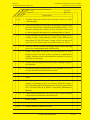
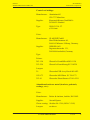
Table of Contents
Chapter
Title
05-00-00
GENERAL
05-10-00
05-10-01
05-10-02
05-10-03
05-10-04
TIME LIMIT COMPONENTS
General
Overhaul Schedule
Recommended Replacement Times
Time between Inspections
05-20-00
05-20-01
05-20-02
05-20-03
05-20-04
05-20-05
SCHEDULED MAINTENANCE CHECKS
General
25 Hour Inspection - Engine
25 Hour Inspection - Aircraft
Maintenance Checks Schedule
Significant Items Inspection
05-50-00
05-50-01
05-50-02
05-50-03
05-50-04
05-50-05
UNSCHEDULED MAINTENANCE CHECKS
Violent Stopping of the Engine (Propeller Strike)
Hard Landing
Engine Fire
Lightning Strike
Flightline Inspections
PAGE DATE: 25. Oktober 2013
................................................................................................................
3
4
4
4
5
5A
.............................................................
...........................................................................................................................
...............................................................................................
.....................................................
.........................................................................
6
6
6
6
11
24
.............................
...........................................................................................................................
.......................................................................
....................................................................
..............................................................
....................................................................
.................
..............
..........................................................................................................
..............................................................................................................
...................................................................................................
.....................................................................................
TEMPORARY REVISION
N° 03702-TR-02-20131025
32
32
32
34
34
35
CHAPTER 05
PAGE
2
EXTRA
SERVICE MANUAL EXTRA 300
05-10-00
TIME LIMIT COMPONENTS
05-10-01
General
All components not listed herein should be inspected as
detailed in Chapter 05-20 „Maintenance Checks“ and repaired, overhauled as required. It is recommended that overhaul or replacement of components should be accomplished
not later than the specified period of operation for that
component or in accordance with the manufacturer's service
data or airworthiness directives.
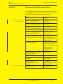
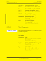
05-10-02
Overhaul Schedule
Items shown here must be overhauled at the times indicated.
Ite m
* refer to latest issue of
Manufacturer´s Service Bulletin
Engine
(Textron Lycoming)
Engine accessories
*
together with engine
Magneto
(Slick)
*
Double magnetos
(Bendix)
*
Propeller
(MT- Propeller)
*
Governor
(Woodward or MT- Propeller)
*
All other components
PAGE DATE: 25. Oktober 2013
Ove rhaul
TEMPORARY REVISION
N° 03702-TR-02-20131025
on Condition
CHAPTER 05
PAGE
4
EXTRA
SERVICE MANUAL EXTRA 300
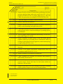
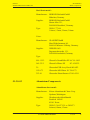
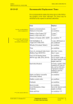
05-10-03
TIME LIMIT COMPONENTS
Recommended Replacement Times
It is recommended to replace the items shown in the following schedule at the times indicated. The times may be
modified by the respective national authorities.
** on the recommendation
of the manufacturer
Ite m
Re place
Battery a) Sonnenschein
Battery b) Concorde
2 years **
on condition
Batteries of the ELT (Pointer)
2 years **
Wheels (Cleveland, Parker)
on condition
Tires
on condition
Fuel, oil, sensing & brake hoses after first 7 years,
(Rubber Type MS28741)
then 5 years
Fuel, Oil & Sensing hoses
on condition,
(PTFE Type MIL- DTL- 25579) but in engine comp. at
the latest together with
engine removal
*** if not stated otherwise
PAGE DATE: 25. Oktober 2013
Seat belts (Hooker)
Rework or replace after
a period of 6 years in
use, service life limit of
national aviation
authority must be
considered
Brake and Brake Assembly
(Cleveland, Parker)
on condition
Rudder control cable
on condition
Fairleads
on condition
Shock mounts
(Lord Kinematics, Barry
Controls)
on condition,
but at the latest at each
engine overhaul
Bolts and Nuts
on condition ***
TEMPORARY REVISION
N° 03702-TR-02-20131025
CHAPTER 05
PAGE
5
EXTRA
SERVICE MANUAL EXTRA 300
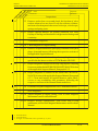
05-10-04
TIME LIMIT COMPONENTS
Time Between Inspections
Inspect these equipment items at the times shown:
PAGE DATE: 25. Oktober 2013
Ite m
Time be twe e n Ins pe ctions
Battery (Concorde)
Refer to Concorde Servicing
Instruction (capacity check)
Static Pressure System
Every 24 calendar months in
accordance with 14 CFR Ch. 1
Part 43 App. E
ATC Transponder
For US registered airplanes:
Every 24 calendar months in
accordance with 14 CFR Ch. 1
Part 43 App. F Par. C and F.
For airplanes registered in other
countries: Observe the latest
national aviation regulations.
TEMPORARY REVISION
N° 03702-TR-02-20131025
CHAPTER 05
PAGE
5A
EXTRA
SERVICE MANUAL EXTRA 300
rs
Date:
s
d o u r hou
e
h 0
Serial No.:
ifi
e c h 5 0 h 10
p
s
c
c
a s e a ea
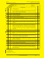
SCHEDULED MAINTENANCE CHECKS
Maintenance Checks Schedule
Inspector:
Mechanic:
Inspections
Engine compartment
(Refer to latest edition of Textron Lycoming Operator´s Manual
and SB's, of Christen Product Manual 801 Series and SB's, of
Slick Magneto Maintenance and Overhaul Manual and SB's and
of TCM/Bendix Service Support Manual, included in Form
X40000 Master Service Manual and SB's)
DANGER
Ground magneto primary circuit before
working on engine
O O
1 Remove engine cowling.
O O
2 Inspect cowling and air inlet screen for damage, cracks,
distortion, overheated areas and loose or missing blindnuts
and secure attachment of oil level access plate.
O O
3 After this inspection clean cowling.
O O
4 Check fire protection according to EXTRA Service Bulletin
300-6-94. On GFRP cowlings repaint the fire protection paint
("WIEDOFLUGAT" N 56582/T508 with clear coat 42320303 or "HENSOTHERM 410KS" with clear coat Glasurit
923-335; refer Chapter 51-30-01) if necessary.
O O O
2
5 Drain oil sump in accordance with Chapter 12-10-04 “Engine
Oil Replenishing”
O1 O O
6 Clean oil suction screen at oil change, check suction screen
for metal particles, shavings, or flakes. Consider Lyc. SB N°
480 latest issue.
O1 O O
7 Clean oil pressure screen at oil change, check pressure screen
for metal particles, shavings, or flakes. Consider Lyc. SB N°
480 latest issue.
O3 O O
8 For engines using a full-flow filtration system:
Replace oil filter.
Remove paper element from filter, carefully unfold the paper
element and examine the material trapped in the filter. Consider Lyc. SB N° 480 latest issue.
1
O
9 Inspect oil temperature sensor unit for leaks and security.
1 each 25 hours for engines employing a pressure screen system
2 a spectrographic oil analysis is recommended at every 50 hours oil change.
3 at 25 hours for new, remanufactured or newly overhauled engines and for engines with any newly installed
cylinders.
PAGE DATE: 25. Oktober 2013
TEMPORARY REVISION
N° 03702-TR-02-20131025
CHAPTER 05
PAGE
13
EXTRA
SERVICE MANUAL EXTRA 300
Date:
rs
s
u r hou
o
h
Serial No.:
0 00
c
pe ch 5 h 1
s
a s e a eac
e
ifi
SCHEDULED MAINTENANCE CHECKS
Maintenance Checks Schedule
Inspector:
d
Mechanic:
Inspections
O O 10 Inspect flexible oil lines, oil return lines and fittings for leaks,
security, chafing, dents, and cracks (ref: FAA AC 43.13-1A).
Replace flexible oil lines at engine TBO per Lyc. SB 240.
Check fire protection according to EXTRA SB 300-6-94.
O 11 Clean and inspect oil radiators and attachment.
O1
12 Remove and flush oil radiators.
O O
O2
Inspect Christen Inverted Oil System for general condition,
leaks, secure mounting and tight connections.
13 Clean and flush the Inverted Oil System with a suitable petroleum solvent, such as varsol according to Lycoming Operator’s Manual.
O3 O O 14 Service engine with recommended lubricating oil in accordance with Chapter 12-10-04.
O O 15 Inspect condition of spark plugs (Clean and adjust gap as
required, adjust per Lycoming Service Instruction 1042). If
fouling of spark plugs has been apparent, rotate buttom plugs
to upper plugs and vice versa.
O O 16 Inspect spark plug cable leads and ceramics for corrosion and
deposits.
O O 17 Perform a hot engine differential compression check in
accordance with FAAAC 43.13-1A.
O 18 Inspect cylinders for cracked or broken fins.
O O 19 Check cylinders for evidence of excessive heat which is
indicated by discoloration.
O 20 Check fuel injector nozzles for loseness. Tighten to 60 inch
pounds torque. Check fuel lines for fuel stains which are
indicative for fuel leaks.
O O 21 Inspect rocker box covers for evidence of oil leaks. If found,
replace gasket; torque cover screws 50 Inch-pounds.
1 each 500 hours
2 each 300 hours
3 each 25 hours
PAGE DATE: 25. Oktober 2013
TEMPORARY REVISION
N° 03702-TR-02-20131025
CHAPTER 05
PAGE
14
EXTRA
SERVICE MANUAL EXTRA 300
Date:
rs
s
u r hou
o
h
Serial No.:
0 00
c
pe ch 5 h 1
s
a s e a eac
e
ifi
O1
SCHEDULED MAINTENANCE CHECKS
Maintenance Checks Schedule
Inspector:
d
Mechanic:
Inspections
22 Remove rocker box covers and check for freedom of valve
rockers when valves are closed. Look for evidence of abnormal wear or broken parts in the area of valve tips, valve keeper,
springs and spring seats.
O 23 Inspect ignition harness for general condition, free from
fraying or chafing and insulators for high tension leakage and
continuity.
TCM/Bendix magnetos
O 24 Check magneto-to-engine timing.
O 25 Remove all ignition harness spark plug terminals from spark
plugs, clean and inspect following the respective sections of
the applicable Support Manual.
O 26 Inspect magnetos with riveted impulse coupling for wear as
specified in the latest revision of TCM/Bendix SB 599D.
O
2
27 Inspect magnetos equipped with snap-ring impulse coupling
for wear as outlined in the PERIODIC MAINTENANCE Section
of the applicable Support Manual, Paragraph 6.2.2.
O2
28 Inspect magnetos as outlined in the PERIODIC MAINTENANCE Section of the applicable Support Manual, Paragraph
6.2.3. Clean and inspect all ignition harness outlet plates,
covers or cap assemblies and grommets following the
respective sections of the Manual mentioned above.
O3
29 Overhaul or replace magnetos acc. to TCM/Bendix SB 643.
Slick magnetos
O 24 Adjust magneto to engine timing, refer to Slick Magneto
Maintenance and Overhaul Manual
O 25 Inspect wiring connections, vent holes and P-lead
attachment, refer to Slick Magneto Maintenance and Overhaul
Manual.
1 each 400 hours
2 each 500 hours
3 at engine overhaul and at the expiration of 4 years
PAGE DATE: 25. Oktober 2013
TEMPORARY REVISION
N° 03702-TR-02-20131025
CHAPTER 05
PAGE
15
EXTRA
SERVICE MANUAL EXTRA 300
SCHEDULED MAINTENANCE CHECKS
Maintenance Checks Schedule
Date:
rs
s
u r hou
o
h
Serial No.:
0 00
c
pe ch 5 h 1
s
a s e a eac
e
ifi
1
Inspector:
d
Mechanic:
Inspections
O
26 Clean magnetos.
O1
27 Inspect ball bearing assembly, impulse coupling, coil, contact
points, condenser and carbon brush.
O2
28 Replace ball bearings.
O1
29 Lubricate magnetos.
3
O
30 Overhaul or replace magnetos.
O 31 Check fuel injector for general condition, clean fuel inlet
screen.
O O 32 Inspect intake seals and O-rings for leaks and clamps for
tightness.
O O 33 Inspect flexible fuel lines, fuel injection lines and fittings for
leaks, security, chafing, dents, and cracks (refer to Lycoming
SB 342 each 100h; replace or overhaul as required or at engine
overhaul). Check fire protection according to EXTRA SB
300-6-94.
O O 34 Check fuel system for leaks.
O4 O O 35 Remove, clean and inspect gascolator screen and fuel filter
bowl.
O O 36 Inspect throttle, mixture, and propeller governor controls for
security, travel, and operating conditions.
O O 37 Inspect exhaust stacks, connections and gaskets (replace
gaskets as required).
O O 38 Inspect exhaust slipjoints for general condition.
O O 39 Inspect exhaust system attachment.
O 40 Inspect crankcase for cracks, leaks, and security of seam bolts.
O O 41 Check engine mounted accessories such as pumps, temperature and pressure sensing units for leaks, secure mounting and
tight connections.
1
2
3
4
each 500 hours
each 1000 hours
together with engine
clean at least every 90 days
PAGE DATE: 25. Oktober 2013
TEMPORARY REVISION
N° 03702-TR-02-20131025
CHAPTER 05
PAGE
16
EXTRA
SERVICE MANUAL EXTRA 300
rs
Date:
r s ou
u
h
o
i
f 0 h 00
Serial No.:
ci
1
p e c h 5 ch
s
a s e a ea
Inspector:
ed
Mechanic:
Inspections
O O 42 Inspect engine mount for cracks and loose mountings.
O O 43 Inspect engine baffles free from cracks and fraying.
O 44 Inspect all wiring connected to the engine or accessories
O O 45 Inspect engine shock mounts for deterioration (replace as
required).
O 46 Inspect firewall seals (see EXTRA SB 300-6-94).
O 47 Inspect alternator, cable connections and accessories.
O 48 Inspect condition and tension of alternator drive belt
O 49 Inspect security of alternator mounting
O 50 Inspect starter and starter drive
O O 51 Check brake fluid level (fill as required).
O O 52 Clean engine if necessary.
O O 53 Lubricate all controls per lubrication chart.
O1
54 Overhaul or replace propeller governor as required.
O2
55 Complete overhaul of engine or replace with factory rebuilt
O O 56 Reinstall engine cowling.
Fuselage
O O
1 Remove tail fairing, tail side skins, tank covering sheet, turtle
deck and landing gear cuffs per Chapter 51.
O
2 Remove bottom covering window and sheets including exhaust area covering sheet per Chapter 51.
O O
3 Inspect tank covering sheet, turtle deck, bottom covering
window and sheets including exhaust area covering sheet, tail
fairing, tail side skins and landing gear cuffs for general
condition, dents, cracks and loose screws and rivets.
O O
4 Check installed parts for general condition and security of
attachment.
1 refer to Woodward Service Bulletin No. 33580
2 refer to Lycoming Service Instruction No. 1009
PAGE DATE: 25. Oktober 2013
TEMPORARY REVISION
N° 03702-TR-02-20131025
CHAPTER 05
PAGE
17
EXTRA
SERVICE MANUAL EXTRA 300
Date:
rs
s
u r hou
o
h
Serial No.:
0 00
c
pe ch 5 h 1
s
a s e a eac
e
ifi
SCHEDULED MAINTENANCE CHECKS
Maintenance Checks Schedule
Inspector:
d
O O
Mechanic:
Inspections
5 Inspect fuselage for foreign matters.
O
6 Inspect steel tube construction for general condition, corrosion and cracks, above all in areas of load stress (e.g. wing,
stabilizer, engine and seat attachments).
O O
7 Visually inspect steel tube construction in the area of horizontal stabilizer attach brackets for cracks. In case of doubt
remove horizontal stabilizer and use a dye check penetrant. In
case of cracks are found contact EXTRA for repair advise.
O O
8 Inspect fabric cover for general condition.
O
9 Inspect wooden longerons for damage.
O 10 Clean and lubricate canopy hinge and latching mechanism.
O O 11 Inspect seats for security, attachment, proper operation, and
condition.
O 12 Inspect breather line for obstructions and security.
O 13 Inspect main and auxiliary wing spar connector for general
condition.
Seat belts
O
1 Check seat belts for security, attachment, proper operation,
and condition.
O
2 Check webbing; inspect for fuzzy edges at the adjusters,
inspect whether edges start to fray, inspect whether webbing
lost its color (top and bottom sides have a different shades).
O
3 Check hardware; inspect for corrosion, check whether buckles mate properly. Check the buckles for easy opening.
O
4 Check ratchet assembly; inspect for corrosion, loss of plating,
discoloration, slippage and wear; check for ease of operation.
If the harness does not pass the check, it has to be reworked or
replaced. Contact the harness manufacturer in case of doubt.
5 Check proper attachment of shoulder harness as per chapter
25-10-03.
PAGE DATE: 25. Oktober 2013
TEMPORARY REVISION
N° 03702-TR-02-20131025
CHAPTER 05
PAGE
18
EXTRA
SERVICE MANUAL EXTRA 300
SCHEDULED MAINTENANCE CHECKS
Maintenance Checks Schedule
Date:
rs
s
u r hou
o
h
Serial No.:
0 00
c
pe ch 5 h 1
s
a s e a eac
e
ifi
Inspector:
d
Mechanic:
Inspections
Fuel system
O O
1 Inspect the fuel lines for leaks, security, chafing, dents and
cracks. Replace fuel lines as required.
O O
2 Inspect fuel selector valve for operation and proper pointer
indication
O O
3 Drain fuel system
O O
4 Check acro- and center tank attachment
O O
5 Check acro-, center- and both wingtanks for leaks
O O
6 Check boost pump
O O
7 Check fuel filler caps for security and proper operation
O O
8 Check proper seat and condition of sealing lip (from S.No 59)
Flight controls
O O
1 Remove wing access panels.
O O
2 Inspect control surfaces for security of attachment, free
movement, dents, delaminations and cracks.
O O
3 Check spades visually for general condition. Inspect spade
support for corrosion, cracks and deformations. Ensure proper
attachment to aileron.
O O
4 Inspect elevator trim system for proper operation and rigging.
O O
5 Inspect hinges for condition, cracks and security; hinge bolts,
hinge bearings, selflocking nuts.
O O
6 Check free play in control system: torque tube, control surfaces,
control sticks, rod end bearing, deflector limiter.
1
O O O
O O
O
7 Lubricate rear torque tube bearing.
8 Lubricate aileron rodend bearings, trim flap hinges and trim
lever bolt.
9 Lubricate adjustment tube of electrical pedal adjustment.
O O 10 Check rudder cable system including sleeves, fairleads, pulleys
and cable retracting springs per FAA-AC 43.13-1A.
1 each 25 hours
PAGE DATE: 25. Oktober 2013
TEMPORARY REVISION
N° 03702-TR-02-20131025
CHAPTER 05
PAGE
19
EXTRA
SERVICE MANUAL EXTRA 300
SCHEDULED MAINTENANCE CHECKS
Maintenance Checks Schedule
Date:
rs
s
u r hou
o
h
Serial No.:
0 00
c
pe ch 5 h 1
s
a s e a eac
e
ifi
Inspector:
d
Mechanic:
Inspections
O 11 Check for minimum 3.5 mm (1/8") clearance of rudder pedal
versus safety stop when fully deflected for rudder cables
having 50 h flight time minimum. On newly installed rudder
cables the minimum spacing is 6 mm (1/4"). Refer to Figure 5.
This check is to be performed with zero loading on the rudder
pedals.
O 12 Rough check of safety stop clearance. With a force of approx.
90 kg (200 lbs) acting on the fully deflected rudder pedal the
safety stop shall not be reached. If the stop is reached the
control system indicates a too high flexibility which needs to
be traced. In this case contact EXTRA for advice.
O O 13 Inspect all flight control ventilation holes for obstruction.
O 14 Inspect elevator balance weight for looseness and condition.
O 15 Inspect push rods.
Landing gear
O O
1 Check landing gear for general condition.
O O
2 Check landing gear spring for dents and cracks.
O O
3 Inspect landing gear spring mounting clamps and bolts for
security.
O
4 Lubricate landing gear center bolt and landing gear bearings.
O
5 Check wheel rake (10° ± 0.5°) and toe-in (1.5° ± 0.5°) per
Chapter 32.
Fairings
O O
1 Disassemble fairings.
O O
2 Check fairings for dents and cracks.
O O
3 Check fairing ventilation hole for obstruction.
Wheels
(refer to on-aircraft inspections presented in the latest edition
of Cleveland Wheels & Brakes Maintenance Manual and
Service Bulletins for wheel, tire and break inspections)
PAGE DATE: 25. Oktober 2013
TEMPORARY REVISION
N° 03702-TR-02-20131025
CHAPTER 05
PAGE
20
EXTRA
SERVICE MANUAL EXTRA 300
Date:
rs
s
ur hou
o
h
Serial No.:
0 00
c
pe ch 5 h 1
s
a s ea eac
e
ifi
SCHEDULED MAINTENANCE CHECKS
Maintenance Checks Schedule
Inspector:
d
Mechanic:
Inspections
O O
1 Visually inspect the wheels for corrosion, cracks, or other
visible damage.
O O
2 Check wheel nuts to be sure they are properly installed and
have not worked loose. Bolt threads should be flush to 1-1/2
threads extending beyond the nut. Nuts should be on the side
of wheel opposite the brake disc (outboard side of wheel).
O O
3 Inspect the brake disc for rust, excessive grooves, large cracks,
coning or other visible damage. Check if disc thickness is
more than 0.325in/8.255mm. Coning of disc in excess of
0.015 in /0.381 mm is cause for replacement (see Fig. 6).
O
4 Remove wheels and wheel bearings. Inspect wheel bearing
grease for contamination and solidification.
O
5 Inspect snap rings and grease seals for distortion or wear.
Replace grease seal felts if they are hard or contaminated.
Lightly saturate grease seals should be replaced if cracked,
dried out, or distorted.
O
6 Inspect wheel bearings for excessive wear or damage. Replace
on condition.
O
7 Repack bearings with AEROSHELL 22C (per MIL-G-81322),
or equivalent. Reinstall wheels and safety.
O O
8 Check wheel bearing clearance and wheels for free rotation.
Tires
O O
1 Visually inspect tires for cuts, flat spots, and tread or sidewall
damage. If changing of tires is necessary follow the instructions, including off-aircraft inspection of wheels, presented in
the Cleveland Wheels & Brakes Component Maintenance
Manual.
O O
2 Check inflation pressure (3.4 bar /49.3 psi). Proper inflation
will provide maximum tire and wheel life.
Brake system
O O
1 Inspect brake assemblies for general condition.
O O
2 Inspect master cylinders for leaks.
PAGE DATE: 25. Oktober 2013
TEMPORARY REVISION
N° 03702-TR-02-20131025
CHAPTER 05
PAGE
21
EXTRA
SERVICE MANUAL EXTRA 300
Date:
rs
s
ur hou
o
h
Serial No.:
0 00
c
pe ch 5 h 1
s
a s ea eac
e
ifi
SCHEDULED MAINTENANCE CHECKS
Maintenance Checks Schedule
Inspector:
d
Mechanic:
Inspections
O
3 Inspect brake system plumbing for leaks and hoses for bulges
and deterioration.
O
4 Lubricate brake guide pins using Silicone-base lubricant.
O O
5 Visually inspect the brakes for corrosion, cracks, or other
visible damage. Check inlet fitting bosses and anchor bolt lugs
for cracks. Check inlet flares on aircraft side of rigid hydraulic
tubing for fatigue cracks.
O O
6 Check back plate attachment bolts to insure they are properly
torqued and have not worked loose. Gaps between the back
plate and cylinder would be evidence of this.
O O
7 Check fit of brake cylinder anchor bolts in torque plate
bushings for sloppiness. This can be accomplished by grasping
the cylinder and moving it; slight movement is normal.
Excessive movement is cause for removal and detailed
inspection.
O O
8 Linings should be visually checked for extreme chipping on
the edges. Lining worn to a minimum thickness of 0.100 inch
(2.54 mm) must be replaced.
O O
9 Visually check torque plate for corrosion, cracks, loose anchor bolt bushings, or other visible damage. Anchor bolt
bushings must be flat against torque plate surface.
O O 10 Check for any brake fluid leaks.
O O 11 Check brake fluid level.
Tail-wheel landing gear
O O
1 Check tail-wheel landing gear for general condition.
O O
2 Check tail-wheel landing gear spring for dents, cracks, and
delaminations.
O O
3 Check tail-wheel rubber tire condition.
O O
4 Inspect tail-wheel spring and swivel arm mounting bolts for
security.
PAGE DATE: 25. Oktober 2013
TEMPORARY REVISION
N° 03702-TR-02-20131025
CHAPTER 05
PAGE
22
EXTRA
SERVICE MANUAL EXTRA 300
Date:
rs
s
ur hou
o
h 0
Serial No.:
i
e c 50 10
p
h
h
s
c
a s ea eac
Inspector:
d
fie
Mechanic:
Inspections
a) Standard: Full-swivel tailwheel
O O
1 Check swivel arm for dents and cracks.
O O
2 Check tail wheel for free rotation and swivel feature.
O
3 Check swivel arm and wheel bearing clearance, service.
b) Optional: Steerable tailwheel
O O
1 Check for general condition and function. Pay attention to the
free movement of the rudder.
O O
2 Check the connector springs for light precompression.
O O
3 Check the wheelfork for free rotation and steering function,
damage, dents, cracks and corrosion.
O O
4 Inspect wheelfork for damage, dents, cracks and corrosion.
O O
5 Inspect the axle bolt and nut for fretting, wear, damage, and
stretch.
O O
6 Lubricate tail wheel steering.
Wing
O O
1 Check wing for dents, cracks, and delaminations.
O
2 Inspect wing spar main bolts for looseness and security.
O
3 Check the safety wire and the safety screw of the wing main
spar bolt.
O
4 Inspect wing spar main sleeves for looseness and bearing load.
O
5 Inspect wing auxiliary spar attachment.
O
6 Inspect wing ventilation holes for obstruction.
O O
7 Check inside wing structure in the area of access panels.
PAGE DATE: 25. Oktober 2013
TEMPORARY REVISION
N° 03702-TR-02-20131025
CHAPTER 05
PAGE
22A
EXTRA
SERVICE MANUAL EXTRA 300
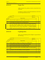
05-50-03
UNSCHEDULED MAINTENANCE CHECKS
Engine Fire
After an engine fire, perform a check as described in the
following:
For damage evaluation consult the manufacturer, before the
aircraft is put back into service.
Date:
Inspector:
Serial No.:
Mechanic:
Inspections
O
1 Check all cables and hoses, replace when necessary
O
2 Check engine according to the Lycoming Manual
O
3 Inspect firewall and engine cowling for damage by high temperatures
(e.g. signs of blisters on the protective paint). If necessary renew LJF
PR 812 seals and, on GFRP cowlings, reapply the fire protection paint
(N56582/T508) and the lacquer 4243-0303 or "HENSOTHERM
410KS" with clear coat Glasurit 923-335; refer Chapter 51-30-01).
05-50-04
Lightning Strike
In the event of a lightning strike in flight or on ground check
the following:
Date:
Inspector:
Serial No.:
Mechanic:
Inspections
O
1 Check engine according to Lycoming Service Bulletin 401.
O
2 Check the skin of the strike area for burns and melting
O
3 Inspect bolts and fasteneners for burns and melting .
O
4 Check the electrical system, with running engine, for correct operation.
O
5 Check the avionic and antenna for correct operation.
O
6 Check the magnetic compass for correct readings.
PAGE DATE: 25. Oktober 2013
TEMPORARY REVISION
N° 03702-TR-02-20131025
CHAPTER 05
PAGE
34
EXTRA
SERVICE MANUAL EXTRA 300
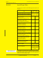
20-10-04
STANDARD PRACTICES AIRFRAME
Special Torque Values
Special torque values for the following items must be adhered to:
Item
Brake Back Plate Bolts (Cleveland)
Wheel Assembly Bolts (Cleveland)
55
480
Engine Mount to Fuselage
(Bolt Din 912, M12-12.9 /
Stop Nut DIN 985, M12-8-B2C)
80
720
Longeron Cutout Bridge
(Bolt DIN 912 M8-8.8 /
Stop Nut LN 9348-08)
18
160
Horizontal Stabilizer Front Spar Bolts
(Bolt LN 9037-10054 /
Stop Nut LN 9348-10)
33
292
Horizontal Stabilizer Rear Spar Bolts
(Bolt LN 9037-08042 /
Stop Nut LN 9348-08), S/N 1 thru 66
14
124
Horizontal Stabilizer Rear Spar Bolts
(Bolt LN 9037-10054 /
Stop Nut LN 9348-10), S/N 67 ff
33
292
Vertical Stabilizer Rear Spar Bolt
(Bolt LN 9037-10054 /
Stop Nut LN 9348-10)
38
336
Wing Main Spar Safety-Bolts
(Bolt LN 9038 K-08020)
15
133
Torque for Propeller
PAGE DATE: 25. Oktober 2013
Refer to Cleveland
Maintenance Manual
Engine Mounting
(Bolts AN7-50A/
Metal Stop Nut NAS 363C-720)
Torque for Engine
I M PO R TAN T
Torque value
(Nm)
(in.lbs)
Refer to Lycoming
Overhaul Manual
Refer to MT-propeller
Installation Manual
E-124
On all bolt connections, the specified torque and locking method must be observed. Do not reuse stop nuts if
they can be run up finger tight!
TEMPORARY REVISION
N° 03702-TR-02-20131025
CHAPTER
PAGE
20
8
EXTRA
SERVICE MANUAL EXTRA 300
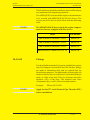
20-10-07
STANDARD PRACTICES AIRFRAME
Flexible Hose
The EXTRA 300 is equipped for the oil, fuel, and brake lines
with "AEROQUIP-hoses Aerospace Division". From Serial
No. 64 equivalent "STRATOFLEX-hoses Aerospace Connectors Division" are used. KNAPP hoses also can be used
for the brake system in the cockpit area and for the flight
instruments. PARKER/STRATOFLEX orAEROQUIP PTFE
type hoses are alternatively used as fuel, oil and sensing
lines. Maintenance work or overhaul of these hoses requires
the attention of the manufacturer informations and bulletins.
For the replacement of hose and hose assemblies EXTRAFlugzeugproduktions- und Vertriebs- GmbH should be contacted.
Replacement of Flexible Hose
Hose and hose assemblies should be checked for deterioration at each inspection period. Leakage, separation of the
cover or braid from the inner tube, cracks, hardening, lack of
flexibility, and excessive "cold flow" are apparent sign of
deterioration and reason for replacement. The term "cold
flow" describes the deep, permanent impressions in the hose
produced by pressure of hose clamps or supports.
The entire assembly must be replaced, if a failure occurs in
a flexible hose before the time limit (refer to Chapter 0510-02 Overhaul Schedule) of the hose is achieved. Obtain
a new hose assembly of the correct size and length, complete
with factory-installed end fittings.
Installation of Flexible Hose Assemblies
The flexible hose must not be twisted on installation, since
this reduces the life of the hose considerably and may
loosen the fittings. Twisting of the hose can be determined
from the identification stripe running along its length.
The minimum bend radius for flexible hose varies according
to size and construction of the hose and the pressure under
which the hose is to operate. Bends that are too sharp will
reduce the bursting pressure of flexible hose considerably
below its rated value.
PAGE DATE: 25. Oktober 2013
TEMPORARY REVISION
N° 03702-TR-02-20131025
CHAPTER
PAGE
20
10
EXTRA
SERVICE MANUAL EXTRA 300
STANDARD PRACTICES AIRFRAME
Flexible Hose
The flexible hose should be installed so that it will be subject
to a minimum of flexing during operation.
The AEROQUIP- hoses inside the engine compartment are
to be covered with AEROQUIP AE102 fire sleeves. The
correct size of fire sleeves can be taken from the following
table:
NOTE
20-10-08
The STRATOFLEX-hoses used in the engine compartment are factory equipped with fire sleeves.
Hose
Fire sleeve
MIL-H-8794-4 / AE303-4 / 111-4
AE102-10
MIL-H-8794-6 / AE303-6 / 111-6
AE102-12
MIL-H-8794-8 / AE303-8 / 111-8
AE102-16
MIL-H-8794-10 / AE303-10 / 111-10
AE102-18
Fittings
For the oil lubrication, the fuel system, and the brake system
only AN-fittings are used in the Extra 300. All these fittings
are made of aluminium alloy and are colored blue for
identification purposes. The dash number following the AN
number indicates the size of the hose for which the fitting is
made, in 16ths of an inch. This size measures the inner
diameter (I.D.) of the hose. The material code letter
(Aluminum alloy: code D) follows the dash number.
Example:
NOTE
PAGE DATE: 25. Oktober 2013
Elbow AN 822-8D
Apply Loctite 577 on all National Pipe Threads (NPT)
before installation.
TEMPORARY REVISION
N° 03702-TR-02-20131025
CHAPTER
PAGE
20
11
EXTRA
SERVICE MANUAL EXTRA 300
TABLE OF CONTENTS
Chapter
Title
25-10-00
25-10-01
25-10-02
25-10-03
25-10-04
FLIGHT COMPARTMENTS
Front seat
Rear seat
Seat belts
Aircraft Document Bag
25-11-00
25-11-01
MAINTENANCE PRACTICES
Reinforcement of Seat Attachment
PAGE DATE: 25. Oktober 2013
................................................................
......................................................................................................................
.......................................................................................................................
......................................................................................................................
...................................................................................
............................................................
TEMPORARY REVISION
N° 03702-TR-02-20131025
.......................................................
CHAPTER
PAGE
3
3
4
5
8
9
9
25
2
EXTRA
SERVICE MANUAL EXTRA 300
FLIGHT COMPARTMENTS
Seat belts
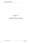
Each strap end is fitted with LN 9037-0820 bolts , LN934808 stop nuts and DIN 125 M8 washers to its own fitting at the
steel frame (refer to Figures 4+5).
Front Seat Belt Attachment
Figure 4
Rear Seat Belt Attachment
Figure 5
The shoulder strap loops of the front and rear seat are
attached to horizontal steel tubes as shown in Figure 6.
PAGE DATE: 25. Oktober 2013
TEMPORARY REVISION
N° 03702-TR-02-20131025
CHAPTER
PAGE
25
6
EXTRA
SERVICE MANUAL EXTRA 300
FLIGHT COMPARTMENTS
Seat belts
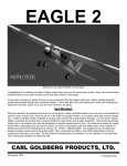
Shoulder Strap Attachment
Figure 6
The shoulder harness shall be installed using the 3-bar slide
as shown in figure 6A.
IMPORTANT
Tuck excess webbing through the 3-bar slide. Failure
to make this third pass through the 3-bar slide will
cause the belt to slip under load.
IMPORTANT
Make shure that after the proper length is determined,
the 3-bar slide is positioned as close to the structure as
possible.
Shoulder Strap Attachment
Figure 6A
PAGE DATE: 25. Oktober 2013
TEMPORARY REVISION
N° 03702-TR-02-20131025
CHAPTER
PAGE
25
7
EXTRA
SERVICE MANUAL EXTRA 300
25-10-04
Aircraft Document Bag
The rear cockpit of the Extra 300 is furnished with an aircraft
document bag. This aircraft document bag is mounted with
three AN 526 C 1032 R8 bolts and DIN 9021 M5x20
washers on the right inside of the cockpit frame.
PAGE DATE: 25. Oktober 2013
TEMPORARY REVISION
N° 03702-TR-02-20131025
CHAPTER
PAGE
25
8
EXTRA
SERVICE MANUAL EXTRA 300
25-11-00
MAINTENANCE PRACTICES
25-11-01
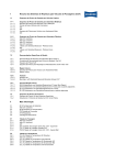
Reinforcement of Seat Attachment
For the Serial No's V1 and 01 thru 63 it is advisable to
strengthen the seat attachments. Weld a reinforcement plate
at the position as shown on Figure 7. Use steel grade
1.7734.4 or AN 4130 in conjunction with the TIG welding
procedure (Tungsten Inert Gas, also called WIG welding) ,
thickness 1mm (0.04").
NOTE
Any welding needs to be done in accordance with FAA
AC43.13-1A manual.
Seat Attachment
Reinforcement
Plate
Reinforcement of Seat Attachment
Figure 7
PAGE DATE: 25. Oktober 2013
TEMPORARY REVISION
N° 03702-TR-02-20131025
CHAPTER
PAGE
25
9
EXTRA
SERVICE MANUAL EXTRA 300
32-11-00
MAINTENANCE PRACTICES
32-11-01
Main Landing Gear
Removal/Installation
Refer to Figure 2.
1 Remove the engine cowling, the landing gear cuffs and
the 1. bottom covering sheet as per chapter 51-00-01.
2 Shore the aircraft as per Chapter 07-20-00
3 Drain brake system.
4 Unfasten the ventilation tubings and disconnect the brake
lines from the brake assembly.
5 Remove the four landing gear attachment stop nuts
(LN9348-8) (1) and the DIN 125 M8 washers.
6 Remove the bottom halves of the mounting clamps (2),
the anti abrasion strips (3) and the landing gear (4).
7 Install in reverse sequence of removal using new stop
nuts. For correct position of landing gear the mandrel,
which is located at the bottom of the fuselage, is to put
into the respective sleeve at the top of the landing gear
spring. Replenish brake fluid per Chapter 12.
32-11-02
Top Half of the Mounting Clamp
Removal/Installation
Refer to Figure 2
1 Remove the main landing gear as per Chapter 32-11-01.
2 Remove the LN9348-10 stop nuts, the DIN125 M10
washers and the LN9037-10054 bolts (5).
3 Remove the top half of the mounting clamp (6).
4 Reverse procedure for installation.
PAGE DATE: 25. Oktober 2013
TEMPORARY REVISION
N° 03702-TR-02-20131025
CHAPTER
PAGE
32
5
EXTRA
SERVICE MANUAL EXTRA 300
TABLE OF CONTENTS
Chapter
Title
34-00-00
GENERAL
34-10-00
34-10-01
34-10-02
34-10-03
FLIGHT ENVIRONMENT DATA
Pitot/Static System
Altimeter
Airspeed Indicator
34-15-00
34-15-01
34-15-02
34-15-03
34-15-04
MAINTENANCE PRACTICES
Pressure Head Removal/Installation
Pitot Head Attachment Block
Removal/Installation
Altimeter Removal/Installation
Airspeed Indicator Removal/Installation
34-20-00
34-20-01
34-20-02
ATTITUDE AND DIRECTION
Magnetic Compass
Turn and Bank Indicator
34-25-00
34-25-01
34-25-02
MAINTENANCE PRACTICES
Magnetic Compass Removal/Installation
Turn and Bank Indicator
Removal/Installation
................................................................................................................
.....................................................
..............................................................................................
......................................................................................................................
................................................................................................
............................................................
....................................................
..........................................................................................
................................................................
.........................................
.............................................................
..............................................................................................
...................................................................................
3
4
4
4
5
6
6
6
7
7
8
8
8
........................................
9
9
..........................................................................................
9
............................................................
34-50-00
34-50-01
DEPENDENT POSITION DETERMINING
Transponder
PAGE DATE: 25. Oktober 2013
TEMPORARY REVISION
N° 03702-TR-02-20131025
.......................
.............................................................................................................
CHAPTER
PAGE
10
10
34
2
EXTRA
SERVICE MANUAL EXTRA 300
34-50-00
DEPENDENT POSITION DETERMINING
34-50-01
Transponder
Various transponders can be installed in the EXTRA 300. A
transponder is a radio transmitter and receiver that fulfills
the role of airborne beacon equipment according to the
requirements of the Air Traffic Radar Beacon System
(ATCRBS). It operates on radar frequencies, receiving ground
radar interrogations at 1030 MHz and transmitting a coded
response of pulses to ground-based radar on a frequency of
1090 MHz.
Removal/Installation
PAGE DATE: 25. Oktober 2013
1
Remove Instrument Cover if transponder has to be installed
from the rear. Refer to Chapter 31-15-01.
2
Remove transponder following the Removal/Installation
Instructions of the respective manufacturer.
3
Install in reverse sequence of removal.
4
Perform an operation test.
TEMPORARY REVISION
N° 03702-TR-02-20131025
CHAPTER
PAGE
34
10
EXTRA
SERVICE MANUAL EXTRA 300
MATERIALS
Composite Part Materials
1006-202/3
Glassit Spritzfüller SP 60-7023
948-36
Glassit Härterpaste, rot SB 48-3360
21-
Glassodur-PUR-Acryl-Lack AD/AE 2
929-73
Glassodur-MS-Härter SC 29-0173
352-91
Glassodur-Einstellzusatz SV 41-0391
923-335
Glasurit Klarlack
(with Hensotherm 410KS)
Manufacturer: Rudolf Hensel GmbH
Lauenburger Landstraße 11
D-21039 Börnsen
Type:
51-30-02
I M PO R TAN T
Fire protective coating:
Hensotherm 410KS
(with 923-335 Glasurit Klarlack)
Metal Components
Only approved materials have to be used for the repair
of metal components.
Steel tubing:
Manufacturer: MHP
Mannesmann Hoesch Präzisrohr GmbH
Postfach 1713,
D-59061 Hamm, Germany
PAGE DATE: 25. Oktober 2013
Supplier:
HEINE+BEISSWENGER Stiftung + CO
Postfach 1510,
D-70705 Fellbach, Germany
Type:
WLB 1.7734.4
18mm x 1.0mm, 20mm x 1.0mm,
22mm x 1.0mm, 22mm x 1.5mm,
25mm x 1.5mm
TEMPORARY REVISION
N° 03702-TR-02-20131025
CHAPTER
PAGE
51
11
EXTRA
SERVICE MANUAL EXTRA 300
MATERIALS
Metal Components
Steel sheet metal :
Manufacturer: BÖHLER Edelstahl GmbH
München, Germany
Supplier:
BÖHLER Edelstahl GmbH
Hansa Allee 321,
D-40549 Düsseldorf, Germany
Type:
WLB 1.7734.4
1.0mm, 1.5mm, 2.0mm, 3.0mm
Paint:
Manufacturer: GLASURITGmbH
Max-Winkelmannstr. 80,
D-48165 Münster / Hiltrup, Germany
Supplier:
WESSELS AG
Pagenstecherstraße 121,
D-49090 Osnabrück, Germany
Type:
51-30-03
801-1552
Glassofix Grundfüller-EP AC 01-1492
965-32/2
Glassofix Härter-EP
21-
Glassodur-PUR-Acryl-Lack AD/AE 2
1929-73
Glassodur-MS-Härter SC 29-0173
352-91
Glassodur-Einstellzusatz SV 41-0391
SC 65-0322
Aluminium Components
Aluminium sheet metal:
Manufacturer: Kaiser Aluminium & Chem. Corp.
Spokane, Washington
PAGE DATE: 25. Oktober 2013
Supplier:
Westdeutscher Metallhandel
Postfach 104245
45141 Essen
Type:
WLB 3.1364. T3511 or 2024 T3
0.6mm; 0.8mm; 1.2mm
TEMPORARY REVISION
N° 03702-TR-02-20131025
CHAPTER
PAGE
51
12
EXTRA
SERVICE MANUAL EXTRA 300
MATERIALS
Aluminium Components
Control rod tubings:
Manufacturer: Aluminium AG
CH-5737 Menziken
Supplier:
Karstens & Knauer GmbH&Co
D-28865 Lilienthal
Type:
WLB 3.1354. T3
ø 25x1mm
Paint:
Manufacturer: GLASURIT GmbH
Max-Winkelmannstr. 80,
D-48165 Münster / Hiltrup, Germany
Supplier:
WESSELS AG
Pagenstecherstraße 121,
D-49090 Osnabrück, Germany
Type:
Primer:
283-150
Glassofix-Grundfüller AB83-1150
352-228
Glassofix-Zusatzlösung SC12-0228
Lacquer:
21-
Glassodur-PUR-Acryl-Lack AD/AE 2
1929-73
Glassodur-MS-Härter SC 29-0173
352-91
Glassodur-Einstellzusatz SV 41-0391
Aluminium hardware metal (brackets, pedestals,
castings, etc.):
Paint:
Manufacturer: Parker & Anchem, Ambler, PA 19002
Supplier:
Aircraft Spruce
Chem. coating: Alodine No. 1201 (MIL-C-5541)
Lacquer:
PAGE DATE: 25. Oktober 2013
see above
TEMPORARY REVISION
N° 03702-TR-02-20131025
CHAPTER
PAGE
51
13
EXTRA
SERVICE MANUAL EXTRA 300
TABLE OF CONTENTS
Chapter
Title
53-00-00
53-00-01
53-01-02
53-00-03
GENERAL . . . . . . . . . . . . . . . . . . . . . . . . . . . . . . . . . . 3
Canopy . . . . . . . . . . . . . . . . . . . . . . . . . . . . . . . . . . . . 11
Canopy Frame . . . . . . . . . . . . . . . . . . . . . . . . . . . . . . . 11
Bottom Fuselage Cover . . . . . . . . . . . . . . . . . . . . . . . . 12
PAGE DATE: 25. Oktober 2013
TEMPORARY REVISION
N° 03702-TR-02-20131025
CHAPTER
PAGE
53
2
EXTRA
SERVICE MANUAL EXTRA 300
53-00-00
GENERAL
GENERAL
The fuselage structure consists of a TIG-welded steel tube
construction integrating the wing and empennage connections as well as the seats (refer to Figure 1).
The particular areas of the fuselage are covered with different materials (also refer to Chapter 51-00-01 "Access Panel
Identification"):
Both halves of the engine cowling consist of glass fibre
laminate and honeycomb. They are coated with fire protection paint ("WIEDOFLUGAT" N 56582 /T508 with clear
coat 4232- 0303 or "HENSOTHERM 410KS" with clear
coat Glasurit 923-335; refer Chapter 51-30-01)
The front part of the fuselage behind the fire wall, the lower
side and the sides below the wing are faired with aluminium
panels. The lower rear part of the fuselage is covered with
fabric. The rear part of the upper fuselage surface (turtle
deck) consists of an aramid laminate.
The one-piece canopy frame is built of carbon fibre laminate
and rovings. The window portion is made of acrylic glass.
The layer sequences of the engine cowlings, the turtle deck
and the tail fairing are shown in Figures 2-5.
All composite parts, as protection against moisture and UV
radiation, are coated with an unsaturated polyester gel-coat,
an acrylic filler and finally with an acrylic paint.
For repair of composite parts and steel components refer to
Chapter 51. The repair of fabric has to be executed in
accordance to the FAA AC 43.13-1A.
PAGE DATE: 25. Oktober 2013
TEMPORARY REVISION
N° 03702-TR-02-20131025
CHAPTER
PAGE
53
3
EXTRA
SERVICE MANUAL EXTRA 300
53-00-03
Bottom Fuselage Cover
Removal
1 Remove engine cowling, the landing gear cuffs and turtle
deck as per chapter 51.
2 Pull the plug of the optional OAT sensor wiring, if applicable.
3 Disconnect the antenna wirings.
4 Remove bottom covering sheets and LEXAN window by removing the attachment screws.
Installation
I M PO R TAN T
The cockpit area must be thoroughly sealed and thus
separated from the engine compartment. Gases or fluids could get into the cockpit area.
Critical areas to be observed are the following:
Position A and D of figure 6, where different parts converge
(firewall, aluminium profile, bottom covering sheet and
exhaust area covering sheet) Position B and C, where a bent
corner ends in a bore hole.
Forward View on Bottom Side Firewall
Figure 6
1 Position aft bottom covering sheet in its original position.
2 Plug the optional OAT sensor wiring and/or antenna wiring,
if applicable.
3 Install aft bottom covering sheet attachment screws.
PAGE DATE: 25. Oktober 2013
TEMPORARY REVISION
N° 03702-TR-02-20131025
CHAPTER
PAGE
53
12
EXTRA
SERVICE MANUAL EXTRA 300
4 Install LEXAN-window.
5 Repeat steps 1 thru 3 for the forward bottom covering sheets.
6 Install bottom cowling attachment screws (one on either
side) without cowling present (see two outer circles in figure 6).
7 Loosen clamp screws on gascolator drain and fuel pump vent
lines for easy access (see inner dotted circles).
8 Prepare PR-812 firewall sealant by mixing brown part A with
black part B with weight ratio 2.5:100.
9 Clean areas (from inside and outside) with solvents at four
positions pointed out by the arrows in figure 6. Immediately thereafter, dry these areas with a new dry cloth.
10 At the gascolator drain (position A) seal the remaining gap
between firewall and bottom fuselage cover from inside and
outside with PR-812 firewall sealant. Minimum sealant
thickness approximately 1/8 inch (= 3 mm).
11 Repeat step 9 at positions B, C and D.
12 Cure time @77°F (25°C), 50%RH for a fillet 1/8 inch
thick:
tack free
approx. 24 hours
to tough rubber
approx. 72 hours
to performance properties
approx. 14 days
13 Fasten clamp screws on gascolator drain and fuel pump vent
lines.
14 Remove the two bottom cowling attachment screws.
15 Reinstall turtle deck, landing gear cuffs and engine cowling
as per Chapter 51.
PAGE DATE: 25. Oktober 2013
TEMPORARY REVISION
N° 03702-TR-02-20131025
CHAPTER
PAGE
53
13